
John Deere Tractors 6403, 6603 Repair Service Manual (TM6024)
Complete Repair Technical Manual for John Deere Tractors 6403 and 6603 (2WD / MFWD America & Cananda).
John Deere 2WD or MFWD - North American Tractors 6403 and 6603 workshop technical manual (repair) includes:
* Numbered table of contents easy to use so that you can find the information you need fast.
* Detailed sub-steps expand on repair procedure information
* Numbered instructions guide you through every repair procedure step by step.
* Notes, cautions and warnings throughout each chapter pinpoint critical information.
* Bold figure number help you quickly match illustrations with instructions.
* Detailed illustrations, drawings and photos guide you through every procedure.
* Enlarged inset helps you identify and examine parts in detail.
tm6024 - 6403 and 6603 Tractors Repair United States-Canada Technical Manual.PDF
tm6024 - 6403 and 6603 Tractors Repair United States-Canada Technical Manual.EPUB
PRODUCT DETAILS:
Total Pages: 1,442 pages
File Format: PDF/EPUB/MOBI/AZW (PC/Mac/Android/Kindle/iPhone/iPad; bookmarked, ToC, Searchable, Printable)
Language: English
MAIN SECTIONS
Foreword
General Information
Safety
Specifications
Fuel and Lubricants
Serial Number Locations
Engine Repair
Engine
Cooling System
Fuel and Air Repair
Fuel System
Speed Control Linkage
Air Intake System
Electrical Repair
Battery, Starter and Alternator
Harness and Connector Repair
Wiring Harness Routing
Electrical System Components
Auxiliary Lighting Components
Fuses And Relays
Lighting
Power Train
Towing
Component Removal
PTO
Clutch
Clutch Housing
Transaxle
Differential
Final Drives
MFWD Drop Gearbox
Steering and Brake Repair
Steering Repair
Front Axle-2WD
Front Axle-MFWD (AS2035)
Front Axle-MFWD (APL350)
Technical Data and Adjustment Values for APL350 ZF Series
Disassembly
Assembling the differential
Pinion depth
Adjusting the play between the teeth
Assembling the Housings
Assembling the Universal Joint
Planet Carrier
Assembling the Hydraulic Cylinder
Convergence Regulation
Brake Repair
Hydraulic Repair
Hydraulic Pump and Filter
Rockshaft
Lubrication System
Selective Control Valve (SCV)
Miscellaneous Repair
Hood and Shields
3-Point Hitch
Wheels
Front Support
Open Operator Station Repair
Seat and Support
ROPS
Operator Platform
Cab Operator Station Repair
Removal and Installation of Components
Selective Control Valve Cable Adjustment
Air Conditioning System
Heating System
Seat
6003 SERIES TOOL KIT (ESSENTIAL TOOL Reference Only)
6003 SERIES TOOL KIT (ESSENTIAL TOOL Reference Only)
SPECIAL TOOLS (Dealer-Fabricated)
tm6024 - 6403 and 6603 Tractors Repair United States-Canada
Table of Contents
Foreword
Section 10: General Information
Group 05: Safety
Recognize Safety Information
Understand Signal Words
Prevent Machine Runaway
Handle Fluids Safely—Avoid Fires
Prevent Battery Explosions
Prepare for Emergencies
Prevent Acid Burns
Handle Chemical Products Safely
Avoid High-Pressure Fluids
Park Machine Safely
Support Machine Properly
Wear Protective Clothing
Work in Clean Area
Service Machines Safely
Work In Ventilated Area
Illuminate Work Area Safely
Replace Safety Signs
Use Proper Lifting Equipment
Construct Dealer-Made Tools Safely
Remove Paint Before Welding or Heating
Avoid Heating Near Pressurized Fluid Lines
Keep ROPS Installed Properly
Service Tires Safely
Avoid Harmful Asbestos Dust
Practice Safe Maintenance
Use Proper Tools
Dispose of Waste Properly
Service Cooling System Safely
Live With Safety
Group 10: Specifications
Machine Specifications and Capacities
Machine Dimensions and Weights
Turning Radius for MFWD 6403 Tractors
Turning Radius for MFWD 6603 Tractors
Turning Radius for 2WD 6603 and 6403 Tractors
Ground Speeds Estimates
Metric Bolt and Screw Torque Values
Unified Inch Bolt and Screw Torque Values
Sealants and Adhesives Cross-Reference Chart
How To Dispense/Apply/Assemble Gasket Sealants
Face Seal Fittings Assembly and Installation—All Pressure Applications
Metric Face Seal Fitting Torque Chart—Standard Pressure Applications
SAE Face Seal Fitting Torque Chart—Standard Pressure Applications
Metric Face Seal Fitting Torque Chart—High Pressure Applications
SAE Face Seal Fitting Torque Chart—High Pressure Applications
Prevent Hydraulic System Contamination
Check Oil Lines and Fittings
Group 15: Fuel and Lubricants
Diesel Fuel
Storing Fuel
Testing Diesel Fuel
Diesel Engine Coolant
Diesel Engine Oil
Transmission and Hydraulic Oil
Fill The Transmission With Oil
Check And Service Transmission Regularly
Transaxle—Assembly Lubrication
Cold Weather Operation
MFWD Gear Oil
Lubricant Storage
Alternative and Synthetic Lubricants
Grease (Specific Application)
Grease
Group 20: Serial Number Locations
Serial Numbers
Product Identification Number Location
Engine Serial Number Location
Fuel Injection Pump Serial Number Location
Alternator Serial Number Location
Transaxle Serial Number Location
Mechanical Front Wheel Drive (MFWD) Serial Number Location
Section 20: Engine Repair
Group 05: Engine
Essential or Recommended Tools
Other Material
Specifications
John Deere Engine Repair—Use CTM104
Remove and Install Engine
Remove Engine Oil Pan
Install Engine Oil Pan
Remove and Install Rocker Arm Cover
Access To Rear Crankshaft Seal
Access To Front Crankshaft Seal
Access To Front Timing Cover
Group 10: Cooling System
Other Material
Specifications
Engine Water Pump Repair—Use CTM104
Remove, Install and Adjust Fan Drive Belt
Inspect and Adjust Alternator/Fan Belt (Cab)
Replacing Fan/Alternator/AC Compressor Belt (Cab)
Remove, Inspect and Install Radiator
Remove and Install Cooling Package
Remove Water Pump
Install Water Pump
Remove Thermostat
Install Thermostat
Pressure Test Cooling System and Radiator Cap
Section 30: Fuel and Air Repair
Group 05: Fuel System
Specifications
Injection Pump, Nozzles and Governor Repair—Use CTM207
Remove and Install Fuel Tank
Replace Fuel Level Sender
Replace Final Fuel Filter and Primary Fuel Filter/Water Separator
Remove and Install Fuel Supply Pump
Bleed Fuel System
Group 10: Speed Control Linkage
Specifications
Inspect and Repair Speed Control Linkage
Adjust Throttle Lever Friction Nut
Adjust Throttle Linkage
Group 15: Air Intake System
Specifications
Replace Air Cleaner Elements/Housing
Inspect and Service Air Intake System
Remove Turbocharger
Install Turbocharger
Turbocharger Break-In
Section 40: Electrical Repair
Group 05: Battery, Starter and Alternator
Specifications
Prevent Battery Explosions
Handling Batteries Safely
Prevent Damage to Electrical Systems
Battery Replacement
Connecting Booster Battery
Charging Batteries
Connecting Battery Cables
Remove and Install Battery
Remove and Install Starter
Starter Repair—Use CTM77
Replace Alternator
Group 10: Harness and Connector Repair
Service Equipment and Tools
Electrical Tool Repair Kit
Wire Repair Pliers
Terminal Applicator
Service Parts Kits
Use Electrical Insulating Compound
Using High-Pressure Washers
Electrical Connector Handling
Connector Identification
Replace WEATHER PACK Connector
Install WEATHER PACK Contact
Remove Connector Body From Blade Terminals
Replace (Pull Type) METRI-PACK METRI-PACK is a trademark of Packard Electric. Connectors
Replace (Push Type) METRI-PACK METRI-PACK is a trademark of Packard Electric. Connectors
Harness Repair—Splice Connector
Wiring Harness Circuit Codes
Group 15: Wiring Harness Routing
Tractor Wiring Harness Replacement
Front Wiring Harness - Reference
Rear Wiring Harness - Reference
Replace Rear Electrical Harness—Cab Tractors
Replace Cab Roof Electrical Harness
HVAC/Wiper Relay Block Assembly
Group 20: Electrical System Components
Service Equipment and Tools
Other Material
Specifications
Replace Air Filter Restriction Switch
Replace Coolant Temperature Sensor
Replace Cold Start Advance Switch
Replace Engine Speed Sensor
Replace Engine Oil Pressure Sensor
Replace Key Switch
Remove and Replace Light Switch
Replace Turn Signal Switch (Open Operator Station)
Replace Turn Signal Switch (Cab Tractors)
Replace Instrument Panel (Open Operator Station)
Replace Instrument Panel (Cab Tractors)
Replace Rear PTO Switch
Replace Neutral Start Switch
Replace Horn Switch (Open Operator Station)
Replace Horn Switch (Cab Tractors)
Replace Horn
Replace Operator Presence Switch
Replace PTO Warning Horn/Timer (OOS Shown)
Replace Starter Relay
Manifold Heater and Relay—Exploded View (If Equipped)
Replace Fan Switch
Replace Switch of the Air-Conditioning System Compressor
Replace Speakers
Replace Antenna
Replace Wiper Control Switch
Replace Wiper Motor
Replace Blower Control Switch
Replace Air Conditioning ON/OFF Switch
Replace A/C Temperature Control Switch
Replace Dome Light
Replace Door Switch
Group 25: Auxiliary Lighting Components
Replace Seven Terminal Outlet Socket
Group 30: Fuses And Relays
Fuse Locations (OOS)
Fuse Location (Cab)
Fuse/Relay Block Assembly (Cab)
Electrical Load Center (Cab)
Relay Locations (OOS)
Fuse Identification
Relay Identification
Diode Block Locations
Group 35: Lighting
Safety Rules When Replacing Halogen Bulbs
Replace Headlight Bulbs
Replace Auxiliary Field Light Bulbs (OOS)
Replace Warning Light Bulb (Cab)
Replace Tail Light Bulb (Cab)
Replace Warning/Tail Light Bulbs (OOS)
Replace Dash Light Bulbs
Section 50: Power Train
Group 00: Towing
Towing Tractor
Adjust Range Shift Lever and Tow Lock
Group 05: Component Removal
Essential or Recommended Tools
Other Material
Specifications
Transaxle Separation
Transaxle Component Identification
Drain Plug Locations
Remove and Install Rear PTO Drive Shaft Assembly
Remove and Install Final Drive Assembly
Remove and Install Clutch
Remove, Inspect and Install MFWD Drive Shaft
Remove and Install MFWD Drop Gearbox
Group 10: PTO
Essential or Recommended Tools
Service Equipment and Tools
Other Material
Specifications
Remove, Inspect and Install PTO Lever and Linkage
Determine PTO Clutch Linkage Adjustment Procedure
Adjust PTO Clutch Linkage- (OOS)
Adjust PTO Clutch Cable - TSS Transmission (Cab Tractors)
Disassemble PTO Housing
Disassemble 540/1000 PTO
Assemble 540/1000 PTO
Disassemble and Assemble 540/1000 RPM PTO Input Shaft
Assemble PTO Housing
Group 15: Clutch
Essential or Recommended Tools
Other Material
Specifications
Separate and Install Engine-to-Clutch Housing
Remove and Install Clutch Linkage
Adjust Interlock Cable
Adjust Clutch Pedal and Linkage
High Capacity Clutch
Disassemble and Inspect Clutch
Assemble Clutch
Adjust Traction Clutch Finger
Adjust PTO Clutch Finger
Group 20: Clutch Housing
Essential or Recommended Tools
Service Equipment and Tools
Other Material
Specifications
Remove and Disassemble Clutch Housing
Disassemble Clutch Engagement Assembly
Assemble Clutch Engagement Assembly
Input Shaft Assembly
Remove Oil Seals and Bearing
Install Oil Seals and Bearing
Assemble Clutch Housing
Install Clutch Housing to Transaxle
Group 25: Transaxle
Essential or Recommended Tools
Service Equipment and Tools
Other Material
Specifications
Disassemble Transaxle Housing
Disassemble Third Stage
Disassemble Bearing Retainer Mounting Plate
Disassemble Second Stage
Assemble Second Stage
First Stage (TSS)
Assemble First Stage (TSS)
Assemble Third Stage (MFWD)
Assemble and Install Transaxle Housing
Group 30: Differential
Service Equipment and Tools
Other Material
Specifications
Remove Differential
Disassemble Differential
Assemble Differential
Disassemble Differential Lock (RH Quill)
Disassemble and Assemble (LH Quill)
Install Differential
Install Differential Lock Lever Stop
Group 35: Final Drives
Essential or Recommended Tools
Service Equipment and Tools
Other Material
Specifications
Axle Housing Removal (LH & RH)
Disassemble Axle Housing
Disassemble Final Drive
Assemble Final Drive
Assemble Axle Housing
Axle Housing Install (LH and RH)
Group 40: MFWD Drop Gearbox
Essential or Recommended Tools
Service Equipment and Tools
Other Material
Specifications
Disassemble MFWD Drop Gearbox
Assemble MFWD Drop Gearbox
Section 60: Steering and Brake Repair
Group 05: Steering Repair
Service Equipment and Tools
Specifications
Service Parts Kits
Remove and Install Steering Wheel
Remove and Install Steering Column (Open Operator Station)
Remove and Install Steering Column (Cab Tractors)
Remove and Install Steering Valve (Open Operator Station)
Remove and Install Steering Valve (Cab Tractors)
Disassemble and Inspect Steering Valve
Assemble Steering Valve
Start-Up Procedure After Hydraulic System Repairs
Group 10: Front Axle—2WD
Essential or Recommended Tools
Other Material
Specifications
Remove Front Axle—2WD
Install Front Axle—2WD
Disassemble Front Axle—2WD
Assemble Front Axle—2WD
Adjust Knuckle and Spindle Assembly Axial Play—2WD
Assemble Wheel Hub—2WD
Adjust Wheel Bearings—2WD
Remove and Install Axle Pivot Pins/Bushings—2WD
Install Tie Rod—2WD
Check And Adjust Toe-In—2WD
Remove and Install Steering Cylinder—2WD
Disassemble, Inspect and Assemble Steering Cylinder—2WD
Group 15: Front Axle—MFWD (AS2035)
Essential or Recommended Tools
Specifications
Remove, Inspect and Install Tie Rod Assembly—MFWD
Disassemble, Inspect and Assemble Steering Cylinder—MFWD
Remove Front Axle—MFWD
Install Front Axle—MFWD
Group 16: Front Axle—MFWD (APL350)
Special Tools For Disassembling and Assembling the Front Wheel Drive Shaft.
Various Special Tools
Group 16A: Technical Data and Adjustment Values for APL350 ZF Series
Technical Data and Adjustment Values
Group 16B: Disassembly
Disassembling the Reducer
Group 16C: Assembling the differential
Assembly
Group 16D: Pinion depth
Pinion depth
Group 16E: Adjusting the play between the teeth
Adjusting the play between the teeth
Group 16F: Assembling the Housings
Assembling the Bridges
Group 16G: Assembling the Universal Joint
Assembling the Universal Joint
Group 16H: Planet Carrier
Planetary Gears Bearing
Group 16I: Assembling the Hydraulic Cylinder
Assembling the Hydraulic Cylinder
Group 16J: Convergence Regulation
Adjust and Check the Turning Direction
Group 20: Brake Repair
Service Equipment and Tools
Other Material
Specifications
Remove and Replace Brake Pedals and Linkage
Adjust Brake Linkage and Pedal Travel
Remove and Install Brakes
Remove and Install Brake Pivot Pins
Remove and Install Brake Boot
Disassemble Brakes (LH and RH)
Disassemble and Assemble Brake Actuators
Assemble Brakes (LH and RH)
Section 70: Hydraulic Repair
Group 05: Hydraulic Pump and Filter
Other Material
Specifications
Service Parts Kits
Remove and Install Hydraulic Oil Cooler
Remove and Install Hydraulic Pump
Disassemble and Inspect Hydraulic Pump
Assemble Hydraulic Pump
Start-Up Procedure After Hydraulic System Repairs
Group 10: Rockshaft
Essential or Recommended Tools
Other Material
Specifications
Service Parts Kit
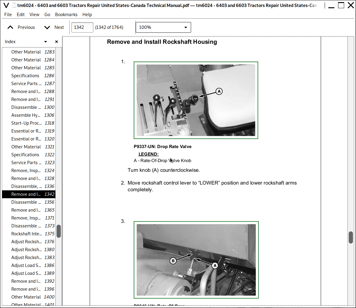
Remove, Inspect and Install Hitch Rate-of-Drop Valve
Remove and Install Rockshaft Control Valve
Disassemble, Inspect and Assemble Rockshaft Control Valve
Remove and Install Rockshaft Housing
Disassemble and Assemble Rockshaft
Remove and Install Rockshaft Cylinder
Remove, Inspect and Replace Rockshaft Internal Linkage
Disassemble and Assemble Rockshaft Control Linkage and Levers
Rockshaft Internal Linkage
Adjust Rockshaft Internal Linkage (Lift Arm Raise Limit)
Adjust Rockshaft Control Lever (OOS Tractors)
Adjust Rockshaft Control Lever (Cab Tractors)
Adjust Load Sense Linkage (OOS Tractors)
Adjust Load Sense Linkage (Cab Tractors)
Group 15: Lubrication System
Remove and Install Lubrication System Relief Valve
Group 20: Selective Control Valve (SCV)
Other Material
Specifications
Service Parts Kits
Remove and Install Selective Control Valve
Disassemble, Inspect and Assemble Selective Control Valve
Section 80: Miscellaneous Repair
Group 05: Hood and Shields
Specifications
Remove and Install Fender Extensions (Open Operator Station)
Remove and Install Fenders—Cab Tractors
Remove and Install Hood
Group 10: 3-Point Hitch
Essential or Recommended Tools
Other Material
Specifications
Inspect and Repair Stabilizer Chains
Inspect and Repair Standard Lift Link
Inspect and Repair Adjustable Lift Link
Inspect and Repair Center Link
Remove and Install Draft Link Pivot Shaft
Remove and Install Drawbar
Group 15: Wheels
Essential or Recommended Tools
Specifications
Remove and Install Front and Rear Wheels
Remove and Install Wheel Rim
Rear Ballast
Remove and Install Front Fender
Group 20: Front Support
Remove, Inspect And Install Front Support
Section 90: Open Operator Station Repair
Group 05: Seat and Support
Specifications
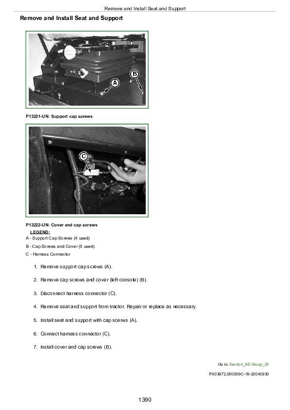
Remove and Install Seat and Support (Deluxe)
Group 10: ROPS
Specifications
Check ROPS
Disassemble ROPS Canopy
Remove and Install ROPS
Group 15: Operator Platform
Other Material
Specifications
Remove Operator Station
Install Operator Station
Section 95: Cab Operator Station Repair
Group 00: Removal and Installation of Components
Service Equipment and Tools
Essential Tools
Specifications
Remove, Inspect, and Install Cab Interior Recirculating Air Filters
Remove, Inspect, and Install Exterior Cab Intake Air Filter
Remove and Install Headliner
Remove and Install Left-Side Upholstery
Remove and Install Right-Side Upholstery
Remove and Install Windshield
Remove and Install Rear Window
Remove and Install Front Lower Windows
Remove and Install Rear Lower Window
Remove and Install Side Windows
Remove and Install Cab Doors
Remove and Install Cab Outer Roof
Remove and Install Safety Exit Door
Installing Door Lock
Remove Operator's Cab
Install Operator's Cab
Group 05: Selective Control Valve Cable Adjustment
Remove and Install Selective Control Valve Cable (Cab Tractors)
Group 10: Air Conditioning System
Essential Tools
Service Equipment and Tools
Other Material
Specifications
Service Parts Kits
Recover/Recycle Air Conditioning Refrigerant
Replace Air Conditioning Receiver-Dryer
Remove, Inspect, and Install Air Conditioning Condenser
Remove, Inspect, and Install Air Conditioning Compressor
Test Volumetric Efficiency of Compressor
Test Compressor Shaft Seal Leakage
Disassemble and Assemble Compressor Clutch
Disassemble, Inspect, and Assemble Compressor
Check Compressor Clutch Hub Clearance
Inspect Compressor Manifold
Remove and Install Compressor Relief Valve
Remove and Install the Evaporator and Expansion Valve
Arrangement of Condensation Water Drain Hoses
Remove and Install Thermostat Switch
Adjust Thermostat Switch Bowden Cable
Remove and Install the High/Low Pressure Switch
Expansion Valve Bench Test
Refrigerant Oil Information
Check Compressor Oil Charge
Determine Correct Refrigerant Oil Charge
Add Refrigerant Oil to System
System Information
Flush Air Conditioning System
Evacuate Air Conditioning System
Charge Air Conditioning System
Group 15: Heating System
Heating System (Summary of References)
Remove and Install Radiator
Remove and Install Fan Motors
Remove and Install Fan Motor Resistors
Remove and Install Heater Valve
Adjust Heater Valve Bowden Cable
Group 20: Seat
Remove and Install Seat and Support
Comfort Seat MSG83
Section 96: 6003 SERIES TOOL KIT (ESSENTIAL TOOL Reference Only)
Group 05: 6003 SERIES TOOL KIT (ESSENTIAL TOOL Reference Only)
Essential or Recommended Tools
JDG6003NA 6003 SERIES TOOL KIT (ESSENTIAL TOOL Reference Only)
Section 99: SPECIAL TOOLS (Dealer-Fabricated)
Group 05: DEALER-FABRICATED TOOLS
DFYZ1—Bearing Driver
DFYZ2—Seal and Bearing Driver
DFYZ3—Roller Bearing Driver
DFYZ4—Bearing Cup Installation Tool
DFYZ5—Driver
DFYZ6—Driver
DFYZ7—Bearing Cone Driver
DFYZ8—Bearing Cone Driver
DFYZ9—Bearing Cup Driver
DFYZ10—Bearing Cup Driver
DFYZ11—Bearing Cone Driver
DFYZ12—Bearing Cup Driver
DFYZ13—Bearing Cone Driver
DFYZ14—Seal Driver
DFYZ15—Bearing Driver
DFYZ16—Bearing Cone Driver
DFYZ17—Bearing Cup Driver
DFYZ18—Bearing Cup Driver
DFYZ19—Bearing Cup Driver
DFYZ20—Bearing Cone Driver
DFYZ21—Seal Driver
DFYZ22—Bearing Cone Driver
DFYZ23—Bearing Driver
DFYZ24—Cup Driver
DFYZ25—Cone Driver
DFYZ26—Cone Driver
DFYZ27—Seal Driver
DFYZ28—Seal Driver
DFYZ29—Bearing Cup Driver
DFYZ30—Bearing Cup Driver
DFYZ31—Bushing Driver
Short Adapter
Input Shaft Seal and Bearing Removal Tool
John Deere Tractors 6403, 6603 Repair Service Manual (TM6024)
![]()