
John Deere 755K Crawler Loader Operation and Test Service Manual (TM12266)
Complete Operation and Test manual with Electrical Wiring Diagrams for John Deere 755K Crawler Loaders, with all the technical information to maintain, diagnose, and service like professional mechanics.
John Deere 755K Crawler Loader workshop Operation and Test manual includes:
* Numbered table of contents easy to use so that you can find the information you need fast.
* Detailed sub-steps expand on repair procedure information
* Numbered instructions guide you through every repair procedure step by step.
* Troubleshooting and electrical service procedures are combined with detailed wiring diagrams for ease of use.
* Notes, cautions and warnings throughout each chapter pinpoint critical information.
* Bold figure number help you quickly match illustrations with instructions.
* Detailed illustrations, drawings and photos guide you through every procedure.
* Enlarged inset helps you identify and examine parts in detail.
TM12266 - John Deere 755K Crawler Loader Technical Manual - Operation and Test.PDF
TM12266 - John Deere 755K Crawler Loader Technical Manual - Operation and Test.epub
Total Pages: 1,811 pages
File Format: PDF (bookmarked, ToC, Searchable, Printable, high quality)
Language: English
MAIN SECTIONS
Foreword
General Information
Safety
Diagnostic Trouble Codes (DTCs)
Engine Control Unit (ECU) Diagnostic Trouble Codes
Standard Display Monitor (SDM) Diagnostic Trouble Codes
Sealed Switch Module (SSM) Diagnostic Trouble Codes
Vehicle Control Unit (VCU) Diagnostic Trouble Codes
Blade Control Joystick (BCJ) Diagnostic Trouble Codes
Electrohydraulic Controller (EHC) Diagnostic Trouble Codes
Operational Checkout Procedure
Operational Checkout Procedure
Engine
Theory of Operation
Diagnostic Information
Adjustments
Tests
Electrical System
System Information
System Diagrams
Sub-System Diagnostics
Monitor Operation
Topcon Integrated Grade Control (IGC) Operation (Factory Installation)
References
Hydraulic System
Theory of Operation
Diagnostic Information
Tests
Hydrostatic System
Theory of Operation
Diagnostic Information
Tests
Heating and Air Conditioning
Theory of Operation
Diagnostic Information
Tests
Reference Material
Tool Information
TABLE OF CONTENTS....1
Section 9000: General Information....23
Group 01: Safety....23
Recognize Safety Information....25
Follow Safety Instructions....26
Operate Only If Qualified....27
Wear Protective Equipment....28
Avoid Unauthorized Machine Modifications....29
Inspect Machine....30
Stay Clear of Moving Parts....31
Avoid High-Pressure Fluids....32
Beware of Exhaust Fumes....33
Prevent Fires....34
Prevent Battery Explosions....35
Handle Chemical Products Safely....36
Dispose of Waste Properly....37
Prepare for Emergencies....38
Add Cab Guarding For Special Uses....39
Use Steps and Handholds Correctly....40
Start Only From Operator's Seat....41
Use and Maintain Seat Belt....42
Prevent Unintended Machine Movement....43
Avoid Work Site Hazards....44
Keep Riders Off Machine....46
Avoid Backover Accidents....47
Avoid Machine Tip Over and Machine Damage....48
Add and Operate Attachments Safely....50
Park and Prepare for Service Safely....51
Service Cooling System Safely....52
Remove Paint Before Welding or Heating....53
Make Welding Repairs Safely....54
Drive Metal Pins Safely....55
Section 9001: Diagnostic Trouble Codes (DTCs)....56
Group 10: Engine Control Unit (ECU) Diagnostic Trouble Codes....68
Engine Control Unit (ECU) Diagnostic Trouble Codes....68
000091.09 - CAN Throttle Missing From VCU....56
000647.05 - Fan Drive Solenoid Open or Short to Power....56
000647.06 - Fan Drive Solenoid Short to Ground....56
001321.09 - Starter Signal Missing....56
001321.16 - Engine Starter Engaged Too Long....56
001321.31 - Starter Solenoid Open Circuit....56
002000.13 - Security Violation....56
002030.09 - No CAN Message Received From Source Address 30....56
002030.19 - Communication Error With Source Address 30....56
003353.31 - Alternator Excitation Condition Exists....56
005484.05 - Fan Reversing Solenoid Open or Short to Power....56
005484.06 - Fan Reversing Solenoid Short to Ground....56
Group 20: Standard Display Monitor (SDM) Diagnostic Trouble Codes....96
Standard Display Monitor (SDM) Diagnostic Trouble Codes....96
000096.03 - Fuel Level Sensor Open or Short....56
000096.04 - Fuel Level Sensor Short to Ground....56
002000.09 - Loss of CAN Communication With ECU....56
002030.09 - Loss of CAN Communication With VCU....56
002141.09 - Loss of CAN Communication With SSM....56
003156.09 - Loss of CAN Communication With EHC....56
Group 30: Sealed Switch Module (SSM) Diagnostic Trouble Codes....117
Sealed Switch Module (SSM) Diagnostic Trouble Codes....117
000444.04 - Invalid Application Configuration....56
000629.12 - Watchdog Timeout....56
000639.12 - Lost CAN Message....56
000639.14 - CAN Bus Off....56
002033.09 - No CAN Messages....56
002634.04 - Ignition Relay Short to Ground....56
002634.05 - Ignition Relay Open....56
520752.04 - Keypad 7 Button Stuck....57
520752.09 - No Message For Keypad 7 Button....57
520753.04 - Washer Button Stuck....57
520753.09 - No Message For Washer Button....57
520754.04 - Keypad 9 Button Stuck....57
520754.09 - No Message For Keypad 9 Button....57
520755.04 - Transmission Up Button Stuck....57
520755.09 - No Message For Transmission Up Button....57
523335.04 - Transmission Down Button Stuck....57
523335.09 - No Message For Transmission Down Button....57
523336.04 - Rear Wiper Button Stuck....57
523336.09 - No Message For Rear Wiper Button....57
523338.04 - Front Wiper Button Stuck....57
523338.09 - No Message For Front Wiper Button....57
523339.04 - Wiper Speed Button Stuck....57
523339.09 - No Message For Wiper Speed Button....57
523340.04 - Standard Lights Button Stuck....57
523340.09 - No Message For Standard Lights Button....57
523849.04 - Work Lights Button Stuck....57
523849.09 - No Message For Work Lights Button....57
523850.04 - Boom Height Kickout Button Stuck....57
523850.09 - No Message For Book Height Kickout Button....57
523852.04 - Keypad 6 Button Stuck....57
523852.09 - No Message For Keypad 6 Button....57
523854.04 - Keypad 5 Button Stuck....57
523854.09 - No Message For Keypad 5 Button....57
523855.04 - Keypad 4 Button Stuck....57
523855.09 - No Message For Keypad 4 Button....57
523856.04 - Auxiliary Power Button Stuck....57
523856.09 - No Message For Auxiliary Power Button....57
523857.04 - Return To Dig Button Stuck....57
523857.09 - No Message For Return To Dig Button....57
523858.04 - Keypad 3 Button Stuck....57
523858.09 - No Message For Keypad 3 Button....58
523860.04 - Keypad 2 Button Stuck....58
523860.09 - No Message For Keypad 2 Button....58
523861.04 - Keypad 1 Button Stuck....58
523861.09 - No Message For Keypad 1 Button....58
523862.04 - Reversing Fan Button Stuck....58
523862.09 - No Message For Reversing Fan Button....58
523863.04 - Hydraulic Enable Button Stuck....58
523863.09 - No Message For Hydraulic Enable Button....58
523864.04 - Undefined Button 4 Stuck....58
523864.09 - No Message For Undefined Button 4....58
523865.04 - Undefined Button 3 Stuck....58
523865.09 - No Message For Undefined Button 3....58
523867.04 - Stop Button Stuck....58
523867.09 - No Message For Stop Button....58
523868.04 - Start Button Stuck....58
523868.09 - No Message For Start Button....58
Group 40: Vehicle Control Unit (VCU) Diagnostic Trouble Codes....233
Vehicle Control Unit (VCU) Diagnostic Trouble Codes....233
000070.00 - Park Lock Lever Inputs Both ON....58
000070.01 - Park Lock Lever Inputs Both OFF....58
000091.03 - Throttle Sensor Short to Power....58
000091.04 - Throttle Sensor Open or Short....58
000116.00 - Brake Pressure High....58
000116.01 - Brake Pressure Low....58
000116.03 - Brake Pressure Short to Power....58
000116.04 - Brake Pressure Open or Short....58
000158.03 - Switched System Volts Too High....58
000158.04 - Switched System Volts Too Low....58
000168.04 - Unswitched System Volts Too Low....58
000177.00 - Trans Oil Temp Overtemp....58
000177.03 - Trans Oil Temp Short to Power....58
000177.04 - Trans Oil Temp Short to Ground....58
000177.16 - Trans Oil Temp Mod Overtemp....59
000190.09 - CAN Comm No Engine Speed....59
000190.19 - CAN Engine Speed Message Invalid Data....59
000521.00 - Decel Sensor Input > Max Cal....59
000521.01 - Decel Sensor Input < Min Cal....59
000521.03 - Decel Sensor Short to Power....59
000521.04 - Decel Sensor Open or Short....59
000521.05 - Decel Sensor Brake Cal Too Lo....59
000521.06 - Decel Sensor Brake Cal Too Hi....59
000521.13 - Decel Sensor Not Calibrated....59
000521.15 - Decel Sensor Min Cal Too High....59
000521.16 - Decel Sensor Max Cal Too High....59
000521.17 - Decel Sensor Min Cal Too Low....59
000521.18 - Decel Sensor Max Cal Too Low....59
000581.00 - Speed Buttons Input > Max Cal....59
000581.01 - Speed Buttons Input < Min Cal....59
000581.03 - Speed Buttons Short to Power....59
000581.04 - Speed Buttons Open or Short....59
000581.07 - Speed Buttons Stuck Button....59
000581.13 - Speed Buttons Not Calibrated....59
000581.15 - Speed Buttons Min Cal Too High....59
000581.16 - Speed Buttons Max Cal Too High....59
000581.17 - Speed Buttons Min Cal Too Low....59
000581.18 - Speed Buttons Max Cal Too Low....59
000604.03 - FNR Neutral Switch Open Circuit....59
000604.04 - FNR Neutral Switch Short Circuit....59
000604.15 - FNR Neut Switch Min Cal Too High....59
000604.16 - FNR Neut Switch Max Cal Too High....59
000604.17 - FNR Neut Switch Min Cal Too Low....59
000604.18 - FNR Neut Switch Max Cal Too Low....59
000619.05 - Brake Solenoid Open or Short to Power....59
000619.06 - Brake Solenoid Short to Ground....59
000629.12 - VCU Watchdog Timer Exceeded....59
000743.05 - Overspeed Solenoid Open or Short to Power....60
000743.06 - Overspeed Solenoid Short to Ground....60
000907.04 - Left Speed Sensor Short to Ground....60
000907.07 - Left Speed Sensor No Response....60
000907.12 - Left Speed Sensor Open....60
000908.04 - Right Speed Sensor Short to Ground....60
000908.07 - Right Speed Sensor No Response....60
000908.12 - Right Speed Sensor Open....60
000924.06 - Aux Power Short to Ground....60
000977.05 - Fan Reverse Solenoid Open or Short to Power....60
000977.06 - Fan Reverse Solenoid Short to Ground....60
001071.05 - Fan Drive Solenoid Open or Short....60
001071.06 - Fan Drive Solenoid Short Circuit....60
001569.31 - Derate Condition Exists on Engine....60
001638.00 - Hyd Oil Temp Overtemp....60
001638.03 - Hyd Oil Temp Short to Power....60
001638.04 - Hyd Oil Temp Short to Gnd....60
001638.16 - Hyd Oil Temp Mod Overtemp....60
001713.31 - Hyd Oil Filter Restricted....60
002000.09 - Loss of CAN Comm With ECU....60
002023.09 - Loss of CAN Comm With SDM....60
002141.09 - Loss of CAN Comm With SSM....60
002251.09 - Communication System Message Missing....60
002355.05 - Front Work Light Open or Short to Power....60
002355.06 - Front Work Light Short to Ground....60
002356.05 - Front Drive Light Open or Short to Power....60
002356.06 - Front Drive Light Short to Ground....60
002359.05 - Rear Drive Light Open or Short to Power....60
002359.06 - Rear Drive Light Short to Ground....60
002660.00 - Steer Sensor Input > Max Cal....60
002660.01 - Steer Sensor Input < Min Cal....60
002660.03 - Steer Sensor Short to Power....60
002660.04 - Steer Sensor Open or Short....60
002660.07 - Steer Sensor Neut Cal Out of Range....61
002660.13 - Steer Sensor Not Calibrated....61
002660.15 - Steer Sensor Min Cal Too High....61
002660.16 - Steer Sensor Max Cal Too High....61
002660.17 - Steer Sensor Min Cal Too Low....61
002660.18 - Steer Sensor Max Cal Too Low....61
002661.00 - FNR Sensor Input > Max Cal....61
002661.01 - FNR Sensor Input < Min Cal....61
002661.03 - FNR Sensor Short to Power....61
002661.04 - FNR Sensor Open or Short....61
002661.07 - FNR Sensor Neut Cal Out of Range....61
002661.13 - FNR Sensor Not Calibrated....61
002661.15 - FNR Sensor Min Cal Too High....61
002661.16 - FNR Sensor Max Cal Too High....61
002661.17 - FNR Sensor Min Cal Too Low....61
002661.18 - FNR Sensor Max Cal Too Low....61
003359.31 - Trans Oil Filter Restricted....61
003509.03 - 5 V Supply #1 Short to Power....61
003509.04 - 5 V Supply #1 Short to Ground....61
003511.03 - 5 V Supply #3 Short to Power....61
003511.04 - 5 V Supply #3 Short to Ground....61
003512.03 - 5 V Supply #4 Short to Power....61
003512.04 - 5 V Supply #4 Short to Ground....61
004087.05 - Hydraulic Enable Solenoid Open or Short to Power....61
004087.06 - Hydraulic Enable Solenoid Short to Ground....61
520570.05 - Transmission Cold Start Solenoid Open or Short to Ground....61
520570.06 - Transmission Cold Start Solenoid Short to Power....61
520571.05 - Fan Unload Solenoid Open or Short....61
520571.06 - Fan Unload Solenoid Short to Power....61
521996.06 - Door Washer Motor Short to Ground....61
521997.05 - Left Door Wiper Open or Short to Power....61
521997.06 - Left Door Wiper Short to Ground....61
521998.05 - Right Door Wiper Open or Short to Power....61
521998.06 - Right Door Wiper Short to Ground....62
521999.00 - Park Lock Lever Inputs Both ON....62
521999.01 - Park Lock Lever Inputs Both OFF....62
522312.06 - Washer Motor Short to Ground....62
522433.05 - Rear Wiper Open or Short to Power....62
522433.06 - Rear Wiper Short to Ground....62
522434.05 - Front Wiper Open or Short to Power....62
522434.06 - Front Wiper Short to Ground....62
522439.05 - Tank Bypass Solenoid Open or Short to Ground....62
522439.06 - Tank Bypass Solenoid Short to Power....62
522440.05 - Blade Left Solenoid Open Circuit....62
522440.06 - Blade Left Solenoid Short Circuit....62
522441.05 - Blade Right Solenoid Open Circuit....62
522441.06 - Blade Right Solenoid Short Circuit....62
522442.00 - Blade Buttons Input Greater Than Maximum Calibration....62
522442.01 - Blade Buttons Input Less Than Minimum Calibration....62
522442.03 - Blade Buttons Short to Power....62
522442.04 - Blade Buttons Open or Short....62
522442.07 - Blade Buttons Stuck Button....62
522444.00 - Charge Pressure High....62
522444.01 - Charge Pressure Low....62
522444.03 - Charge Pressure Short to Power....62
522444.04 - Charge Pressure Open or Short....62
522447.05 - Right Fwd Pump Coil Open or Short....62
522447.06 - Right Fwd Pump Coil Short to Power....62
522447.15 - Right Fwd Pump Thresh Cal High....62
522447.16 - Right Fwd Pump Max Spd Cal High....62
522447.17 - Right Fwd Pump Thresh Cal Low....62
522447.18 - Right Fwd Pump Max Spd Cal Low....62
522448.05 - Right Rev Pump Coil Open or Short....62
522448.06 - Right Rev Pump Coil Short to Power....62
522448.15 - Right Rev Pump Thresh Cal High....62
522448.16 - Right Rev Pump Max Spd Cal High....62
522448.17 - Right Rev Pump Thresh Cal Low....63
522448.18 - Right Rev Pump Max Spd Cal Low....63
522449.05 - Left Rev Pump Coil Open or Short....63
522449.06 - Left Rev Pump Coil Short to Power....63
522449.15 - Left Rev Pump Thresh Cal High....63
522449.16 - Left Rev Pump Max Spd Cal High....63
522449.17 - Left Rev Pump Thresh Cal Low....63
522449.18 - Left Rev Pump Max Spd Cal Low....63
522450.05 - Left Fwd Pump Coil Open or Short....63
522450.06 - Left Fwd Pump Coil Short to Power....63
522450.15 - Left Fwd Pump Thresh Cal High....63
522450.16 - Left Fwd Pump Max Spd Cal High....63
522450.17 - Left Fwd Pump Thresh Cal Low....63
522450.18 - Left Fwd Pump Max Spd Cal Low....63
522451.05 - Cooler Bypass Solenoid No Response....63
522451.06 - Cooler Bypass Solenoid Short to Power....63
523108.13 - Pump/Motor Not Calibrated....63
523108.14 - VCU Not Calibrated....63
523577.05 - Left Motor Sol Open or Short....63
523577.06 - Left Motor Sol Short to Power....63
523577.13 - Motor High Speed Not Calibrated....63
523577.16 - Left Motor Max Cal Too High....63
523577.18 - Left Motor Max Cal Too Low....63
523578.05 - Right Motor Sol Open or Short....63
523578.06 - Right Motor Sol Short to Power....63
523578.16 - Right Motor Max Cal Too High....63
523578.18 - Right Motor Maximum Calibration Too Low....63
524089.00 - Left Hydrostatic Pressure Sensor—Pressure High....63
524089.01 - Left Hydrostatic Pressure Sensor—Pressure Low....63
524089.03 - Left Hydrostatic Pressure Sensor Voltage OOR High....63
524089.04 - Left Hydrostatic Pressure Sensor Voltage OOR Low....63
524090.00 - Right Hydrostatic Pressure Sensor—Pressure High....63
524090.01 - Right Hydrostatic Pressure Sensor—Pressure Low....63
524090.03 - Right Hydrostatic Pressure Sensor Voltage OOR High....64
524090.04 - Right Hydrostatic Pressure Sensor Voltage OOR Low....64
524233.07 - Hydrostatic Drive System Not Responding....64
Group 50: Blade Control Joystick (BCJ) Diagnostic Trouble Codes....64
Diagnostic Trouble Code (DTC) Quick Reference List—Blade Control Joystick (BCJ)....775
000444.01 - Switched Power Circuit Fault....64
002697.03 - Voltage Too High (X Axis)....64
002697.04 - Voltage Too Low (X Axis)....64
002697.12 - Internal Failure (X Axis)....64
002697.13 - Input Not Calibrated (X Axis)....64
002697.14 - Redundant Input Failure (X Axis)....64
002698.03 - Voltage Too High (Y Axis)....64
002698.04 - Voltage Too Low (Y Axis)....64
002698.12 - Internal Failure (Y Axis)....64
002698.13 - Input Not Calibrated (Y Axis)....64
002698.14 - Redundant Input Failure (Y Axis)....64
Group 60: Electrohydraulic Controller (EHC) Diagnostic Trouble Codes....64
Diagnostic Trouble Code (DTC) Quick Reference List—Electrohydraulic Controller (EHC)....789
000158.03 - EHC System Volts Too High....64
000158.04 - EHC System Volts Too Low....64
000620.03 - Sensor Short to Power....64
000620.04 - Sensor Short to Ground....64
001903.00 - Auxiliary 1 PVE Open Circuit....64
001903.01 - Auxiliary 1 PVE Low or Open Circuit....64
001903.03 - Auxiliary 1 PVE Short to Power....64
001903.04 - Auxiliary 1 PVE Short to Ground....64
001903.31 - Auxiliary 1 PVE Spool Position Error....64
001915.00 - Auxiliary 2 PVE Open Circuit....64
001915.01 - Auxiliary 2 PVE Low or Open Circuit....64
001915.03 - Auxiliary 2 PVE Short to Power....64
001915.04 - Auxiliary 2 PVE Short to Gound....64
001915.31 - Auxiliary 2 PVE Spool Position Error....64
002000.09 - Missing ECU CAN Data....64
002030.09 - Missing VCU CAN Data....65
002697.09 - CAN Joystick Position Missing From BCJ....65
003157.03 - Increment/Decrement Buttons Short to Power....65
003157.04 - Increment/Decrement Buttons Open or Short....65
003157.31 - Increment/Decrement Buttons Invalid Output....65
522442.03 - Blade Buttons Short to Power....65
522442.04 - Blade Buttons Open or Short....65
522422.31 - Blade Buttons Invalid Output....65
523779.00 - Blade Rotate Current Above Maximum....65
523779.01 - Blade Rotate Current Below Minimum....65
523780.00 - Tilt PVE Open Circuit....65
523780.01 - Tilt PVE Low or Open Circuit....65
523780.03 - Tilt PVE Short to Power....65
523780.04 - Tilt PVE Short to Ground....65
523780.31 - Tilt PVE Spool Position Error....65
523781.00 - Height PVE Open Circuit....65
523781.01 - Height PVE Low or Open Circuit....65
523781.03 - Height PVE Short to Power....65
523781.04 - Height PVE Short to Ground....65
523781.31 - Height PVE Spool Position Error....65
524059.00 - Auxiliary 2 Joystick Sensor 2 Volts High....65
524059.01 - Auxiliary 2 Joystick Sensor 2 Volts Low....65
524059.03 - Auxiliary 2 Joystick Sensor 2 Short to Power....65
524059.04 - Auxiliary 2 Joystick Sensor 2 Short to Ground....65
524059.31 - Auxiliary 2 Joystick Sensor 2 Invalid Output....65
524062.00 - Auxiliary 1 Joystick Sensor 2 Volts High....65
524062.01 - Auxiliary 1 Joystick Sensor 2 Volts Low....65
524062.03 - Auxiliary 1 Joystick Sensor 2 Short to Power....65
524062.04 - Auxiliary 1 Joystick Sensor 2 Short to Ground....65
524062.31 - Auxiliary 1 Joystick Sensor 2 Invalid Output....65
524085.00 - Auxiliary 2 Joystick Sensor 1 Volts High....65
524085.01 - Auxiliary 2 Joystick Sensor 1 Volts Low....65
524085.03 - Auxiliary 2 Joystick Sensor 1 Short to Power....65
524085.04 - Auxiliary 2 Joystick Sensor 1 Short to Ground....66
524085.14 - Auxiliary 2 Joystick Sensor Mismatch....66
524085.31 - Auxiliary 2 Joystick Sensor 1 Invalid Output....66
524086.00 - Auxiliary 1 Joystick Sensor 1 Volts High....66
524086.01 - Auxiliary 1 Joystick Sensor 1 Volts Low....66
524086.03 - Auxiliary 1 Joystick Sensor 1 Short to Power....66
524086.04 - Auxiliary 1 Joystick Sensor 1 Short to Ground....66
524086.14 - Auxiliary 1 Joystick Sensor Mismatch....66
524086.31 - Auxiliary 1 Joystick Sensor 1 Invalid Output....66
Section 9005: Operational Checkout Procedure....899
Group 10: Operational Checkout Procedure....899
Operational Checkout....953
Section 9010: Engine....1006
Group 05: Theory of Operation....1006
John Deere Engine....1031
Cold Start Aid System Theory of Operation—If Equipped....1009
Fast Fill Fuel System Theory of Operation—If Equipped....1011
Group 15: Diagnostic Information....1006
John Deere Diesel Engine....1014
Engine Cooling System Component Location....1015
Engine Fuel System Component Location....1017
Engine Intake and Exhaust Component Location....1020
Fast Fill Fuel System Underfill—If Equipped....1006
Fast Fill Fuel System Overfill—If Equipped....1006
Fast Fill Fuel System Nozzle Leaks at Receiver—If Equipped....1006
Group 20: Adjustments....1006
John Deere Engine....1031
Service Filter Cleaning....1029
Group 25: Tests....1006
John Deere Engine....1031
Low-Pressure Fuel Pump Pressure Test....1032
Fluid Sampling Procedure—If Equipped....1033
Engine Idle Speeds and Auto Shutdown Check....1038
Exhaust Emissions Test Point....1040
Section 9015: Electrical System....1042
Group 05: System Information....1042
Electrical Diagram Information....1050
Electrical Schematic Symbols....1054
Group 10: System Diagrams....1042
Fuse and Relay Specifications....1061
System Functional Schematic, Component Location, and Wiring Diagram Master Legend....1065
System Functional Schematic....1074
System Functional Schematic—Integrated Grade Control (IGC)....1083
JDLink™ Functional Schematic....1092
Engine Interface Harness (W10) Component Location....1093
Engine Interface Harness (W10) Wiring Diagram....1095
Cooling Package Harness (W11) Component Location....1097
Cooling Package Harness (W11) Wiring Diagram....1098
Fan Harness (W12) Component Location....1099
Fan Harness (W12) Wiring Diagram....1100
Vehicle Harness (W13) Component Location....1101
Vehicle Harness (W13) Wiring Diagram....1103
Vehicle (IGC Controls) Harness (W14) Component Location....1107
Vehicle (IGC Controls) Harness (W14) Wiring Diagram....1109
Engine Compartment Light Harness (W15) Component Location....1114
Engine Compartment Light Harness (W15) Wiring Diagram....1115
Fuel Tank Harness (W16) Component Location....1116
Fuel Tank Harness (W16) Wiring Diagram....1117
Operator's Station Harness (W17) Component Location....1118
Operator's Station Harness (W17) Wiring Diagram....1120
Operator's Station (IGC Controls) Harness (W18) Component Location....1122
Operator's Station (IGC Controls) Harness (W18) Wiring Diagram....1124
Front Dash Harness (W19) Component Location....1127
Front Dash Harness (W19) Wiring Diagram....1128
Left Console Harness (W20) Component Location....1129
Left Console Harness (W20) Wiring Diagram....1130
Cab Roof Harness (W21) Component Location....1131
Cab Roof Harness (W21) Wiring Diagram....1133
Canopy Roof Harness (W22) Component Location....1135
Canopy Roof Harness (W22) Wiring Diagram....1137
Radio Harness (W23) Component Location....1138
Radio Harness (W23) Wiring Diagram....1139
Heater and Air Conditioner Harness (W24) Component Location....1140
Heater and Air Conditioner Harness (W24) Wiring Diagram....1141
Condenser Harness (W25) Component Location....1143
Condenser Harness (W25) Wiring Diagram....1144
Under Seat Heater Harness (W26) Component Location....1145
Under Seat Heater Harness (W26) Wiring Diagram....1146
Dome Light Harness (W28) Component Location....1147
Dome Light Harness (W28) Wiring Diagram....1148
Engine Harness (W29) Component Location....1149
Engine Harness (W29) Wiring Diagram....1152
Intake Air Sensor Harness (W30) Component Location....1154
Intake Air Sensor Harness (W30) Wiring Diagram....1155
Front Engine Harness (W31) Component Location....1156
Front Engine Harness (W31) Wiring Diagram....1157
Fuel Dosing Harness (W32) Component Location....1158
Fuel Dosing Harness (W32) Wiring Diagram....1159
Fuel Injector Harness (W34) Component Location....1160
Fuel Injector Harness (W34) Wiring Diagram....1161
Alternator Resistor Harness (W35) Component Location....1162
Alternator Resistor Harness (W35) Wiring Diagram....1163
Glow Plug Harnesses (W36 and W37) Component Location....1164
Glow Plug Harnesses (W36 and W37) Wiring Diagrams....1166
Left IGC Grille Harness (W43) Wiring Diagram....1279
Right IGC Grille Harness (W44) Wiring Diagram....1169
JDLink™ Harnesses (W6002 and W6003) Component Location....1170
Modular Telematics Gateway (MTG) Harness (W6002) Wiring Diagram....1171
Satellite (SAT) Harness (W6003) Wiring Diagram....1173
Group 15: Sub-System Diagnostics....1043
Start and Charge Circuits Theory of Operation....1179
Park Brake Circuit Theory of Operation....1184
Controller Area Network (CAN) Theory of Operation....1187
Engine Control Unit (ECU) Circuit Theory of Operation....1193
Vehicle Control Unit (VCU) Circuit Theory of Operation....1210
Standard Display Monitor (SDM) Circuit Theory of Operation....1228
Integrated Grade Control (IGC) Circuit Theory of Operation—If Equipped....1231
Exhaust Aftertreatment Circuit Theory of Operation....1237
Group 16: Monitor Operation....1044
Standard Display Monitor (SDM)—Service Mode....1243
Standard Display Monitor (SDM)—Codes....1245
Standard Display Monitor (SDM)—Exhaust Filter....1246
Standard Display Monitor (SDM)—Service....1248
Standard Display Monitor (SDM)—Machine Settings....1250
Standard Display Monitor (SDM)—Diagnostics....1254
Standard Display Monitor (SDM)—Monitor....1257
Standard Display Monitor (SDM)—Calibrate....1259
Standard Display Monitor (SDM)—Vehicle Control Unit (VCU) Diagnostics....1260
Standard Display Monitor (SDM)—Software Delivery....1262
Group 17: Topcon® Integrated Grade Control (IGC) Operation (Factory Installation)....1044
Topcon® Integrated Grade Control (IGC) Circuit Schematic (Factory Installation)....1267
Topcon® Integrated Grade Control (IGC) Circuit Theory of Operation (Factory Installation)....1270
IGC Controller/Receiver Harnesses (W40 and W41) Component Location....1273
IGC Controller/Receiver Harness 1 (W40) Wiring Diagram....1274
IGC Controller/Receiver Harness 2 (W41) Wiring Diagram....1275
IGC Display Unit Harness (W42) Component Location....1276
IGC Display Unit Harness (W42) Wiring Diagram....1277
IGC Grille Harness (W43) Component Location....1278
IGC Grille Harness (W43) Wiring Diagram....1279
Group 20: References....1044
Electrical Component Specifications....1288
Service ADVISOR™ Diagnostic Application....1296
Service ADVISOR™ Connection Procedure....1297
Reading Diagnostic Trouble Codes with Service ADVISOR™ Diagnostic Application....1300
Diagnostic Trouble Codes—After Machine Repair....1303
Integrated Grade Control (IGC) Checks—If Equipped....1045
Integrated Grade Control (IGC) Diagnose Malfunctions—If Equipped....1045
CAN Circuit Test....1335
Alternator Test Procedure....1347
Vehicle Control Unit (VCU) Calibration....1349
Wire Harness Test....1351
Decelerator/Brake Pedal Adjustment....1352
Engine Speed Control Remove and Install....1354
Exhaust Filter Sensor Installation....1356
Rotary Sensor Remove and Install....1357
Air Conditioner Freeze Switch Remove and Install....1359
Transmission Control Lever (TCL) Adjustment....1361
Controller Remove and Install....1365
Intermittent Diagnostic Trouble Code (DTC) Diagnostics....1366
Replace Weather Pack™ Connector....1367
Install Weather Pack™ Contact....1369
Replace DEUTSCH® Connectors....1371
Replace DEUTSCH® Rectangular or Triangular Connectors....1373
Install DEUTSCH® Contact....1375
Replace CINCH® Connectors....1377
Install CINCH® Contact....1379
Repair 32 and 48 Way CINCH® Connectors....1381
Replace (Pull Type) Metri-Pack™ Connectors....1385
Replace (Push Type) Metri-Pack™ Connectors....1387
Section 9025: Hydraulic System....1388
Group 05: Theory of Operation....1388
Hydraulic System Operation....1392
Hydraulic Pump Operation....1394
Pressure Reducing Valve Operation....1405
Pilot Control Valve Operation....1408
Hydraulic Control Valve Operation....1410
Hydraulic Control Valve Operation—IGC....1412
Load Sense Circuit Operation....1417
Load Sense Isolator Operation....1418
Load Sense Relief Valve Operation....1419
Engine Overspeed Protection Valve Operation....1421
Hydraulic System Relief Valve Operation....1424
Circuit Relief Valve with Anticavitation Operation....1425
Hydraulic Oil Filter Manifold Operation....1427
Blade Angle Operation....1430
Ripper Operation....1434
Ripper Operation—Integrated Grade Control (IGC)....1435
Hydraulic Cylinder Operation....1436
Quick-Drop Valve Operation....1437
Hydraulic Reversing Fan Drive Operation....1439
Group 15: Diagnostic Information....1388
Hydraulic System Schematic....1456
Hydraulic System Schematic—Integrated Grade Control (IGC)....1470
Hydraulic System Line Identification....1474
Hydraulic System Line Identification—Integrated Grade Control (IGC)....1479
Main Hydraulic Component Location....1482
Main Hydraulic Component Location—Integrated Grade Control (IGC)....1484
Ripper Hydraulic Component Location....1485
Ripper Hydraulic Component Location—Integrated Grade Control (IGC)....1486
Winch Ready Hydraulic Component Location....1487
Hydraulic System Diagnose Malfunctions....1388
Hydraulic System Diagnose Malfunctions—IGC....1388
Hydraulic Fan Does Not Reach Full Speed....1389
Hydraulic Fan Runs at Full Speed Only....1389
Hydraulic Fan Does Not Spin....1389
Hydraulic Fan Will Not Reverse Direction....1389
Group 25: Tests....1389
JT02156A Digital Pressure and Temperature Analyzer Kit Installation....1533
Ultra Clean® Hand Launcher....1671
Hydraulic Oil Cleanup Procedure....1688
Hydraulic Accumulator Discharge Procedure....1536
Hydraulic Accumulator Precharge Test....1537
Pump Load Sense Differential and System Pressure (Load Sense Relief) Test and Adjustment....1539
Pump Load Sense Differential and System Pressure (Load Sense Relief) Test and Adjustment—IGC....1543
Pump Cut-Off Pressure Test and Adjustment....1547
Hydraulic System Relief Valve Test....1551
Hydraulic System Relief Valve Test—IGC....1556
Circuit Relief Valve Test....1559
Circuit Relief Valve Test—IGC....1561
Lift and Tilt Cylinder Function Drift Test....1563
Cylinder Leakage Test....1566
Pressure Reducing Valve Pressure Test and Adjustment....1568
Hydraulic Pump Flow Test....1571
Hydraulic Pump Case Drain Test....1574
Fan Pump Flow Test....1577
Fan Motor Speed Test....1580
Fan Motor Case Drain Test....1583
Section 9026: Hydrostatic System....1585
Group 05: Theory of Operation....1585
Hydrostatic System Operation....1588
Transmission Control Circuit Operation (Flow Chart)....1589
Charge Pump Operation....1591
Hydrostatic Charge Oil Filter Operation....1592
Neutral Charge Relief Valve Operation....1594
Multi-Function Valve Operation....1595
Hydraulic Integrated Circuit (HIC) Valve Operation....1597
Park Brake Valve Operation....1599
Oil Cooler and Reservoir Bypass Operation....1601
Pump Pressure Control Pilot (PCP) Operation....1603
Pump Displacement Control Valve (PDCV) Operation....1605
Hydrostatic Pump Operation....1607
Flushing Valve and Operating Charge Relief Valve Operation....1609
Hydrostatic Motor Operation....1611
Hydrostatic Cold Start Valve Operation....1613
Group 15: Diagnostic Information....1585
Hydrostatic System Schematic—Neutral (Park Brake On)....1616
Hydrostatic System Component Location....1618
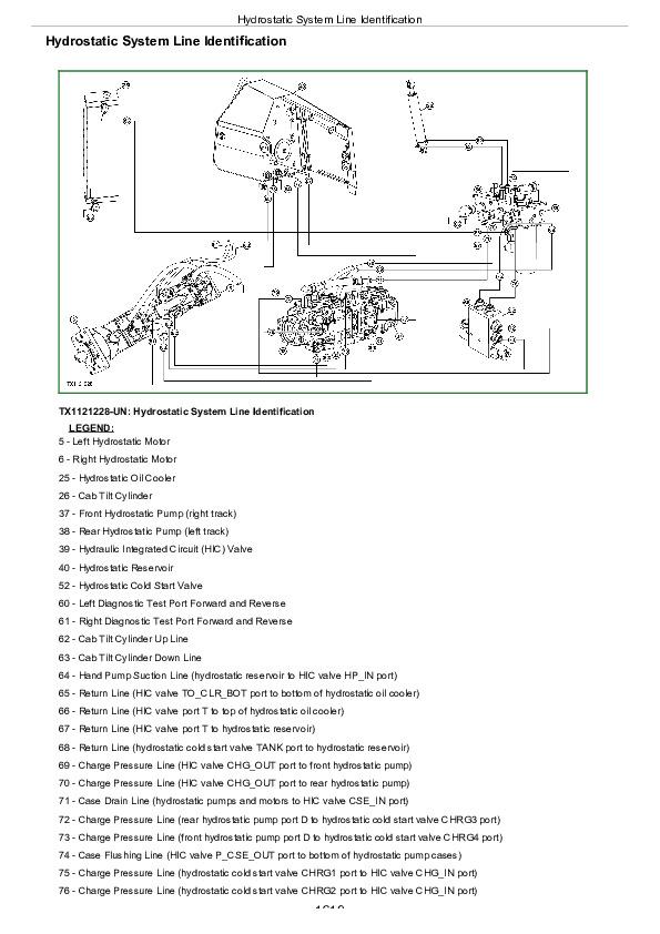
Hydrostatic System Line Identification....1619
Park Brake System Component Location....1621
Hydrostatic System Diagram—Neutral (Park Brake On)....1623
Hydrostatic System Diagram—Reverse (Slow Speed)....1625
Hydrostatic System Diagram—Forward (Fast Speed)....1627
Overheating Malfunctions....1585
Low Charge Pressure Malfunctions....1585
Mistrack/Index Malfunctions....1585
Machine Full Speed Malfunctions....1585
Low Power Malfunctions....1585
Track Malfunctions....1585
VCU Calibration Malfunctions....1585
Group 25: Tests....1586
Ultra Clean® Hand Launcher....1671
Machine Supporting Procedure....1672
Transmission Oil Warm-Up Procedure....1676
Releasing Park Brake to Tow the Machine....1679
Hydrostatic Pump and Motor Initial Start-Up Procedure....1684
Hydrostatic Pump Flushing Procedure....1686
Hydraulic Oil Cleanup Procedure....1688
Pressure Control Pilot (PCP) Manual Override Test....1689
Pressure Control Pilot (PCP) Test....1691
Pressure Control Pilot (PCP) Internal Adjustment....1695
Multi-Function Relief Valve Test....1698
Transmission Efficiency Test....1703
Neutral Charge Relief and Operating Charge Relief Pressure Test....1708
Pump Displacement Control Valve (PDCV) Neutral (Null) Adjustment....1711
Pump Servo Pressure Test....1715
Motor Displacement Control Valve (MDCV) Adjustment....1719
Hydrostatic Motor Min./Max. Angle Servo Piston Pressure Test....1723
Charge Pump Flow Test....1726
Charge Pressure Sensor Test....1729
Hydrostatic Cold Start Valve Test....1731
Hydrostatic Oil Cooler Bypass Test....1735
Hydrostatic Oil Reservoir Bypass Test....1739
Park Brake Test....1744
Park Brake Relief Valve Test....1750
Cab Tilt Relief Valve Test....1752
Hand Pump Bleed Procedure....1754
Section 9031: Heating and Air Conditioning....1755
Group 05: Theory of Operation....1755
Air Conditioning System Cycle Theory Of Operation....1758
Group 15: Diagnostic Information....1755
Heater and Air Conditioner System Component Location....1762
Under Seat Heater System Component Location....1764
Diagnose Air Conditioning System Malfunctions....1765
Air Conditioner System Does Not Operate....1755
Air Conditioner Does Not Cool Interior of Cab....1755
Air Conditioner Runs Constantly, Too Cool....1755
Diagnose Heater System Malfunctions....1776
Heater System Does Not Operate....1755
Heater Does Not Warm Interior of Cab....1755
Interior Windows Continue to Fog....1755
Group 25: Tests....1755
Refrigerant Cautions and Proper Handling....1786
R134a Refrigerant Cautions....1787
Air Conditioner and Heater Operational Checks....1788
R134a Oil Charge Capacity....1791
R134a Refrigerant Charge Capacity....1792
Refrigerant Hoses And Tubing Inspection....1793
Refrigerant Leak Test....1794
Air Conditioner Compressor Clutch Test....1795
Air Conditioner High/Low Pressure Switch Test....1796
Air Conditioner Freeze Control Switch Test....1799
R134a Air Conditioning System Test....1801
Operating Pressure Diagnostic Chart....1804
Section 9050: Reference Material....1806
Group 10: Tool Information....1806
JDG11446 750K Spacer Bar Installation....1809
John Deere 755K Crawler Loader Operation and Test Service Manual (TM12266)
![]()