
John Deere Crawler Dozers 750C, 850C, 750C Series II, 850C Series II Repair Service Manual (TM1589)
Complete service repair manual for John Deere Crawler Dozers 750C, 850C, 750C Series II, 850C Series II, with workshop information to maintain, repair, and service like professional mechanics.
John Deere Crawler Dozers 750C, 850C, 750C Series II, 850C Series II workshop service repair manual includes:
* Numbered table of contents easy to use so that you can find the information you need fast.
* Detailed sub-steps expand on repair procedure information
* Numbered instructions guide you through every repair procedure step by step.
* Notes, cautions and warnings throughout each chapter pinpoint critical information.
* Bold figure number help you quickly match illustrations with instructions.
* Detailed illustrations, drawings and photos guide you through every procedure.
* Enlarged inset helps you identify and examine parts in detail.
for complete service information also see:
750C, 850C, Crawler Dozer Operation and Test - TM1588
6068 Engine - CTM8
6068 POWERTECH Engine - CTM104
6076 Engine - CTM42
6081 POWERTECH Engine Repair - CTM86
Undercarriage Appraisal Manual - SP326
TM1589 - 750C, 850C, 750C Series II, 850C Series II Crawler Dozers Technical Manual (Repair).pdf
TM9010 - Reparación Bulldozer sobre orugas 750C, 750C Serie II,850C, 850C Serie II.pdf
Total Pages: 997 pages
File Format: PDF (bookmarked, ToC, Searchable, Printable)
Category: Repair
Language: English Spanish
Published on 2018/03/01
Main Sections
Foreword
Technical Information Feedback Form
General Information
Safety
General Specifications
Torque Values
Fuels and Lubricants
Tracks
Track System
Dealer Fabricated Tools
Axles and Suspension Systems
Drive Axle Housing and Support
Axle Shaft, Bearings and Reduction Gears
Dealer Fabricated Tools
Transmission
Remove and Install
Control Linkage
Hydrostatic System
Dealer Fabricated Tools
Engine
Removal and Installation
Engine Auxiliary Systems
Cold Weather Starting Aid
Cooling System
Speed Controls
Intake System
External Exhaust Systems
External Fuel Supply Systems
Dealer Fabricated Tools
Dampener Drive
Elements
Park Brake
Park Brake
Control Linkage
Hydraulic System
Equipment Attaching
Drawbar
Electrical System
Batteries, Support, and Cables
Alternator, Regulator and Charging System Wiring
Lighting System
Wiring Harness and Switches
System Controls
Motors and Actuators
Frames, Chassis, or Supporting Structure
Frame Installation
Frame Bottom Guards
Chassis Weights
Operator’s Station
Removal and Installation
Operator Enclosure
Seat and Seat Belt
Heating and Air Conditioning
Sheet Metal
Hood and Engine Enclosures
Grille and Grille Housing
Safety, Convenience and Miscellaneous
Horn and Warning Devices
Bulldozer
Removal and Installation
Blade
Controls Linkage
Frames
Hydraulic System
Dealer Fabricated Tools
tm1589 - 750C, 750C Series II, 850C, 850C Series II Crawler Dozer
Table of Contents
Foreword
Technical Information Feedback Form
Section 00: General Information
Group 01: Safety
Handle Fluids Safely—Avoid Fires
Prevent Battery Explosions
Prepare for Emergencies
Prevent Acid Burns
Handle Chemical Products Safely
Avoid High-Pressure Fluids
Park Machine Safely
Support Machine Properly
Wear Protective Clothing
Work in Clean Area
Service Machines Safely
Work In Ventilated Area
Illuminate Work Area Safely
Replace Safety Signs
Use Proper Lifting Equipment
Remove Paint Before Welding or Heating
Avoid Heating Near Pressurized Fluid Lines
Keep ROPS Installed Properly
Practice Safe Maintenance
Decommissioning — Proper Recycling and Disposal of Fluids and Components
Live With Safety
Group 02: General Specifications
750C Series II Specifications
750C Series II Capacity Specifications
750C Series II General Specifications
750C LT Series II Dimensions
750C WT Series II Dimensions
750C LGP Series II Dimensions
850C Series II Specifications
850C Series II Capacity Specifications
850C Series II General Specifications
850C LT Series II Dimensions
850C WT Series II Dimensions
850C LGP Series II Dimensions
Group 03: Torque Values
Hardware Torque Specifications
Keeping ROPS Installed Properly
Checking Track Shoe Cap Screw Torque
Checking Track Shoe Cap Screw Torque—Master Link
Metric Bolt and Screw Torque Values
Additional Metric Cap Screw Torque Values
Service Recommendations for Metric Series Four Bolt Flange Fitting
Unified Inch Bolt and Screw Torque Values
Check Oil Lines And Fittings
Service Recommendations for O-Ring Boss Fittings
Service Recommendations For Flat Face O-Ring Seal Fittings
Service Recommendations For Inch Series Four Bolt Flange Fittings
Group 04: Fuels and Lubricants
Diesel Fuel
Handling and Storing Diesel Fuel
Fuel Tank
Low Sulfur Diesel Fuel Conditioner
Diesel Fuel Storage
Diesel Engine Oil — Non-Emissions Certified and Certified Tier 1 and Stage I
Transmission, Hydraulic, and Hand Pump Reservoir Oil
Inner and Outer Final Drive Oil
Track Rollers, Front Idler, Carrier Roller and Track Frame Outer Pivot Oil
Grease
Lubricant Storage
Alternative and Synthetic Lubricants
Mixing of Lubricants
Diesel Engine Coolant (engine with wet sleeve cylinder liners)
Section 01: Tracks
Group 0130: Track System
Essential Tools
Service Equipment and Tools
Other Material
Specifications
Remove and Install Rock Guards and Track Guides
Measure Carrier Roller Wear
Remove and Install Carrier Roller
Disassemble and Assemble Carrier Roller
Inspect Metal Face Seals
Test Carrier Roller for Oil Leakage
Measure Track Roller Wear
Remove and Install Track Roller
Disassemble Track Roller
Assemble Track Roller
Test Track Roller for Leakage
Measure Track Shoe Grouser Wear
Remove and Install Track Shoe
Exploded View of Front Crossbar and Support—750C
Remove and Install Front Crossbar and Support—750C
Remove and Install Front Crossbar and Support—850C (S.N. —833331)
Check and Adjust Front Crossbar-to-Crossbar Support and Main Frame Clearances (S.N. —833331)
Remove and Install Support Wear Plates (S.N. —833331)
Remove and Install Pinned Crossbar and Support—850C (S.N. 833332—907600)
Remove and Install Crossbar and Lube Lines—850C (S.N. 907601— )
Disassemble and Assemble Crossbar—850C (907601— )
Measure Link Height
Measure Bushing Outside Diameter for Lubricated Track Chain
Measure Track Pitch for Lubricated Track Chain
Remove and Install Lubricated Track Chain
Disassemble Lubricated Track Chain to Turn Bushings and Lubricate Chain
Assemble Lubricated Track Chain to Turn Bushings and Lubricate Chain
Disassemble and Assemble Lubricated Track Chain to Turn Pins and Bushings and Not Lubricate
Adjust Track Sag
Track Adjuster Exploded View
Remove Track Adjuster and Recoil Spring
Install Track Adjuster and Recoil Spring
Disassemble and Assemble Recoil Spring
Disassemble and Assemble Track Adjuster Cylinder
Remove Track Frame
Welding Procedure
Remove and Install A-Frame Bearing and A-Frame Bushings
Install Track Frame
Remove and Install Wear Strip on Inner Guide
Remove and Install Track Frame Upper Wear Strips
Remove and Install Track Frame Lower Wear Strips
Remove and Install Track Frame Wear Strip Bar
Measure Front Idler Wear
Remove Front Idler
Disassemble Front Idler
Inspect Metal Face Seals
Exploded View of Front Idler
Assemble Front Idler
Install Front Idler
Adjust Front Idler Vertical Movement
Adjust Front Idler Horizontal Movement
Test Front Idler for Oil Leakage
Remove and Install Sprocket Segment
Group 0199: Dealer Fabricated Tools
DFT1087 Track Recoil Spring Compression Tool Guard
DF1041 Track Nut Removal Tool
ST4920 Track Recoil Spring Compression Tool
Section 02: Axles and Suspension Systems
Group 0201: Drive Axle Housing and Support
Service Equipment and Tools
Other Material
Specifications
Remove and Install Final Drive Axle Housing And Support
Group 0250: Axle Shaft, Bearings and Reduction Gears
Service Equipment and Tools
Other Material
Specifications
Planet Carrier Housing Assembly Cross Section
Remove and Install Planet Housing
Disassemble and Assemble Planet Carrier Housing
Remove Ring Gear, Hub and Sprocket Frame
Disassemble and Assemble Ring Gear Hub and Sprocket Frame
Inspect Metal Face Seals
Install Gear, Hub and Sprocket Frame
Remove and Install Final Drive Housing Assembly
Disassemble and Assemble Final Drive Housing Cover Assembly
Group 0299: Dealer Fabricated Tools
Dealer Fabricated Tools
DFT1079 Final Drive Lifting Fixture Adapter
DFT1260 Final Drive Lifting Fixture
Section 03: Transmission
Group 0300: Remove and Install
Essential Tools
Service Equipment and Tools
Other Material
Specifications
Remove and Install Hydrostatic Pumps
Remove and Install Hydrostatic Motors
Hydrostatic Motor Speed Sensor Adjustment
Hydrostatic Pump and Motor Initial Start-Up Procedure
Group 0315: Control Linkage
Essential Tools
Service Equipment and Tools
Other Material
Specifications
Remove and Install Steering Pedal
Disassemble and Assemble FNR Control Assembly—Pedal Steer (S.N. —883331)
FNR Control Assembly Component Location—Pedal Steer (S.N. —883331)
FNR and Neutral Start Switch Adjustment—Pedal Steer (S.N. —883331)
Disassemble and Assemble FNR Control Assembly—Single Lever Steer (S.N. —883331)
FNR Control Assembly Component Location—Single Lever Steer (S.N. —883331)
FNR and Neutral Start Switch Adjustment—Single Lever Steer (S.N. —883331)
Single Lever Control (SLC) Exploded View With Speed In Grip (S.N. 883332— )
Remove and Install Single Lever Control (SLC) With Speed In Grip (S.N. 883332— )
Disassemble and Assemble Single Lever Control Linkage (SLC) With Speed In Grip (S.N. 883332— )
Rotary Sensor Component Location With (SIG) Speed In Grip (S.N. 883332— )
Park Lock Linkage Adjustment
Group 0360: Hydrostatic System
Essential Tools
Service Equipment and Tools
Other Material
Specifications
Disassemble Hydrostatic Pump
Disassemble and Assemble Charge Pump
Disassemble and Assemble Pump Displacement Control Valve (PDCV)
Remove and Install Multi-Function Valve
Remove and Install Charge Pressure Manifold
Disassemble and Assemble Multi-Function Valve
Assemble Hydrostatic Pump
Disassemble and Assemble Oil Cooler Bypass Valve
Disassemble Hydrostatic Motor
Assemble Hydrostatic Motor
Remove and Install Hydrostatic Oil Filter
Group 0399: Dealer Fabricated Tools
DFT1063 Pump Lifting Bracket
DFT1130 Adapter
DFT1132 Hydrostatic Motor Removal and Installation Tool
DFT1137 Hydrostatic Motor Removal and Installation Tool
DFT1164 Speed Sensor Adjusting Tool
Section 04: Engine
Group 0400: Removal and Installation
6068 John Deere Engine—Use CTM8
6068 John Deere POWERTECH POWERTECH is a trademark of Deere & Company Engine—Use CTM104
6076 John Deere Engine—Use CTM42
6081 John Deere POWERTECH POWERTECH is a trademark of Deere & Company Engine Repair—Use CTM86
Essential Tools
Other Material
Specifications
Remove and Install Engine
Remove and Install Oil Pan
Remove and Install Fuel Filter Check Valve—850C
Remove DB4 Fuel Injection Pump—750C
Installing DB4 Fuel Injection Pump—750C
Remove In-Line Fuel Injection Pump—850C
Install In-Line Fuel Injection Pump—850C
JT07158 TIME TRAC TIME TRAC is a registered trademark of Stanadyne Automotive Corp, Installation
Injection Pump Dynamic Timing—750C
Fuel Shut-Off Solenoid Adjustment—850C (S.N. —822867)
Disassemble and Assemble Final Fuel Filter—750C
Disassemble and Assemble Primary Fuel Filter (Water Separator)
Bleed the Fuel System—750C
Bleed the Fuel System—850C
Primary Fuel Filter, Drain Valve—750C
Primary Fuel Filter, Drain Valve—850C
Remove and Install Engine Mounts
Section 05: Engine Auxiliary Systems
Group 0505: Cold Weather Starting Aid
Specifications
Remove and Install Engine Coolant Heater
Group 0510: Cooling System
6068 John Deere Engine—Use CTM8
6068 John Deere POWERTECH POWERTECH is a trademark of Deere & Company Engine—Use CTM104
6076 John Deere Engine—Use CTM42
6081 John Deere POWERTECH POWERTECH is a trademark of Deere & Company Engine Repair—Use CTM86
Essential Tools
Service Equipment and Tools
Specifications
Remove and Install Guards, Shroud and Fan
Remove and Install Fan Belt and Adjuster—750C (S.N.—831315)
Remove, Install, Inspect Serpentine Belt
Remove and Install Radiator and Oil Cooler
Remove and Install Hydraulic Oil Cooler
Group 0515: Speed Controls
Essential Tools
Service Equipment and Tools
Other Material
Specifications
JT05801 Clamp-On Digital Tachometer Installation
Remove and Install Engine Speed Control
Remove and Install Engine Speed Control Linkage and Shaft 750C and 850C (S.N. —822867)
Remove and Install Engine Speed Control Linkage and Shaft 850C (S.N. 822868—)
Engine Speed Control Linkage Rod—850C (S.N. —822867)
Engine Speed Control Linkage Rod—750C
Remove and Install Decelerator
Engine Speed Adjustment—750C
Engine Speed Adjustment—850C
Engine Speed Control Cable Adjustment
Engine Speed Control Sensor Adjustment (750C, 850C S.N.—875378)
Decelerator Sensor Adjustment—Single Lever Steer
Throttle Sensor Adjustment—850C (S.N. 822868— )
Group 0520: Intake System
Remove and Install Air Cleaner
Test Air Intake System for Leaks
Group 0530: External Exhaust Systems
Remove and Install Muffler
Group 0560: External Fuel Supply Systems
Other Material
Specifications
Remove and Install Fuel Tank
Remove and Install Fuel Lines—750C
Remove and Install Fuel Lines—850C
Group 0599: Dealer Fabricated Tools
DFT1140 Serpentine Belt Removal and Installation Tool (850C)
Section 07: Dampener Drive
Group 0752: Elements
Other Material
Specifications
Remove and Install Dampener Drive
Replace Dampener Drive—750C
Section 11: Park Brake
Group 1100: Park Brake
Specifications
Park Brake Cross Section
Remove and Install Park Brakes
Group 1115: Control Linkage
Service Equipment and Tools
Specifications
Remove and Install Park Brake Pedal
Remove and Install Park Brake Valve Linkage
Remove and Install Park Lock Lever and Brake Cable and Linkage
Park Lock Linkage Adjustment
Group 1160: Hydraulic System
Remove and Install Park Brake Valve
Disassemble and Assemble Park Brake Valve
Section 15: Equipment Attaching
Group 1511: Drawbar
Specifications
Remove and Install Extended Rigid Drawbar
Remove and Install Rigid Drawbar
Section 16: Electrical System
Group 1671: Batteries, Support, and Cables
Service Equipment and Tools
Specifications
Service Batteries Carefully
Procedure for Testing Batteries
Checking Electrolyte Specific Gravity
Check Battery Electrolyte Level and Terminals
Using Booster Batteries—24 Volt System
Charge Battery
Remove and Install Batteries
Group 1672: Alternator, Regulator and Charging System Wiring
Alternators and Starting Motors—Use CTM77
Essential Tools
Specifications
Remove and Install Alternator
Group 1673: Lighting System
Remove and Install Light Switch
Remove and Install Halogen Bulb
Remove and Install Dome Light and Swivel Light
Group 1674: Wiring Harness and Switches
Essential Tools
Cab/ROPS Harness Component Identification—(750C S.N. —883331) and (850C S.N. —822867)
Cab/ROPS Harness Component Identification—850C (S.N. 822868—883331)
Cab/ROPS Harness Component Identification—750C, 850C (S.N. 883332— )
Chassis Harness Component Identification
Engine/Pump Harness Component Identification—750C (S.N. —831315)
Engine/Pump Harness Component Identification—750C (S.N. 831316— )
Engine/Pump Harness Component Identification—850C (S.N. —822867)
Engine/Pump Harness Component Identification—850C (S.N. 822868—)
Grille Housing Harness Component Identification—750C (S.N. —831315) and 850C (S.N. —822867)
Grille Housing Harness Component Identification—750C (S.N. 831316— ) and 850C (S.N. 822868— )
Motor Harness Electrical Component Identification
Wiper Harness Electrical Component Identification
A/C Compressor Harness Component Identification—750C (S.N. —831315) and 850C (S.N. —822867)
A/C Condenser Harness Electrical Component Identification
Replace DEUTSCH DEUTSCH is a trademark of Deutsch Co. Connectors
Install DEUTSCH DEUTSCH is a trademark of Deutsch Co. Contact
Replace WEATHER PACK WEATHER PACK is a trademark of Packard Electric. Connectors
Install WEATHER PACK WEATHER PACK is a trademark of Packard Electric. Contact
Replace METRI-PACK METRI-PACK is a trademark of Packard Electric Connector
Remove Connector Body from Blade Terminals
Group 1675: System Controls
Welding Procedure
Remove and Install Transmission Controller
Remove and Install Display Monitor
Remove and Install Engine Controller—850C (S.N. 822868— )
Group 1677: Motors and Actuators
John Deere Starting Motor—Use CTM77
Remove and Install Starting Motor
Section 17: Frames, Chassis, or Supporting Structure
Group 1740: Frame Installation
Specifications
Welding Repair of Major Structures
Remove and Install Sub-Frame Fasteners
Group 1746: Frame Bottom Guards
Other Material
Remove and Install Bottom Guards—750C
Remove and Install Bottom Guards—850C
Group 1749: Chassis Weights
Specifications
Remove and Install Counterweight—850C
Section 18: Operator’s Station
Group 1800: Removal and Installation
Service Equipment and Tools
Specifications
Remove and Install Cab/ROPS
Group 1810: Operator Enclosure
Other Material
Specifications
Disassemble and Assemble Cab/ROPS Tilt Cylinder
Remove and Install Cab/ROPS Tilt Cylinder
Remove and Install Hand Pump Assembly
Disassemble and Assemble Hand Pump
Remove and Install Cab/ROPS Mounts and Isolators
Remove and Install Window
Remove and Install Windowpanes
Remove and Install Cab Covers
Remove and Install Wiper Motor Assemblies
Remove and Install Cab Doors and Hinges
Remove and Install Door Hold Open Latch
Remove and Install Windshield Washer
Group 1821: Seat and Seat Belt
Disassemble and Assemble Seat
Group 1830: Heating and Air Conditioning
Essential Tools
Service Equipment and Tools
Other Material
Specifications
R134a Refrigerant Theory of Operation
R134a Refrigerant Cautions
R134a Compressor Oil Charge Check
R134a Compressor Oil Removal
R134a Component Oil Charge
R134a Refrigerant Recovery, Recycling and Charging Station Installation Procedure
Recover R134a System
Evacuate R134a System
Charge R134a System
Check and Adjust Compressor Belt Tension—750C (S.N. —831315)
Remove and Install Air Conditioning Compressor—750C (S.N. —831315)
Remove and Install Air Conditioning Compressor—750C (S.N. 831316— )
Remove and Install Air Conditioning Compressor—850C
Disassemble and Inspect Compressor
Assemble Compressor
Inspect Compressor Manifolds
Remove and Install Receiver/Dryer
Remove and Install Evaporator
Remove and Install Condenser
Remove and Install Heater Pressurizer
Section 19: Sheet Metal
Group 1910: Hood and Engine Enclosures
Specifications
Remove and Install Hood
Remove and Install Hood Support and Engine Side Shields
Group 1921: Grille and Grille Housing
Specifications
Remove and Install Grille Housing
Section 20: Safety, Convenience and Miscellaneous
Group 2004: Horn and Warning Devices
Remove and Install Reverse Alarm
Adjust Reverse Warning Alarm Volume
Section 32: Bulldozer
Group 3200: Removal and Installation
Specifications
Remove and Install Angledozer or Bulldozer Blade and Frame (Outside Dozer)
Remove and Install Trunnion (Outside Dozer)
Trunnion Shim Adjustment and 850C Pat Trunnion (S.N. —898365)
Trunnion Shim Adjustment 850C (PAT) (S.N. 898366— )
Remove and Install (PAT) All Hydraulic Blade with C—Frame 850C
Group 3201: Blade
Specifications
Remove and Install Bulldozer (Outside Dozer)
Remove and Install Cutting Edges and End Bits
Remove and Install (PAT) Six Way Blade 850C
Group 3215: Controls Linkage
Other Material
Specifications
Remove and Install T-Bar Linkage
Remove and Install Two Function Hydraulic Linkage
Remove and Install Third Function Hydraulic Linkage
Group 3240: Frames
Specifications
Remove and Install Bulldozer Pushbeam
Remove and Install Pitch Jack
Remove and Install Struts
Disassemble and Assemble Pushbeams, Struts and Pitch Jack
Blade Pitch Adjustment
Disassemble and Assemble Lift Cylinder Pivot Sub-frame
Group 3260: Hydraulic System
Special or Essential Tools
Service Equipment and Tools
Other Material
Specifications
Remove and Install Hydraulic Pump
Disassemble and Assemble Hydraulic Pump
Remove and Install Plug Or Winch PTO Shaft From Hydraulic Pump
Remove and Install Hydrostatic and Hydraulic Reservoir
Hydraulic and Hydrostatic Reservoir Cleanout Cover Remove and Install (S.N. 925753— )
Disassemble and Assemble Reservoir
Remove and Install Hydraulic Filter
Disassemble and Assemble Hydraulic Filter
Remove and Install Dozer Control Valve
Component Location—All Hydraulic Dozer
Component Location—Bulldozer Hydraulics
Component Location—Angle Dozer Hydraulics
Component Location—850C (PAT) Blade (S.N. 883332— )
Disassemble and Assemble Dozer Control Valve
Installing Valve Seal Kit in Cap End
Installing Valve Seal Kit in Tang End
Disassemble and Assemble System Relief Valve
Disassemble and Assemble Circuit Relief Valve with Anti-Cavitation
Remove and Install Quick Drop Valve
Disassemble and Assemble Quick Drop Valve
Remove and Install Tilt Cylinder—Outside Dozer
Cross Section of a 180 Series (Tilt) Cylinder—Outside Dozer
Disassemble Tilt Cylinder—Outside Dozer
Assemble Tilt Cylinder—Outside Dozer
Remove and Install Blade Lift Cylinder—Outside Dozer
Disassemble and Assemble Blade Lift Cylinder (S.N.—831315 )
Disassemble and Assemble Blade Lift Cylinder—Outside Dozer (S.N. 831316— )
Remove and Install Tilt Cylinder For (PAT) Six-Way Blade 850C (S.N. —883331)
Remove and Install Angle Cylinder For (PAT) Six-Way Blade 850C (S.N. —883331)
Disassemble 120 Series Blade Tilt (PAT) (S.N. 883332— ) and Lift Cylinder (PAT) (S.N. 883332— )
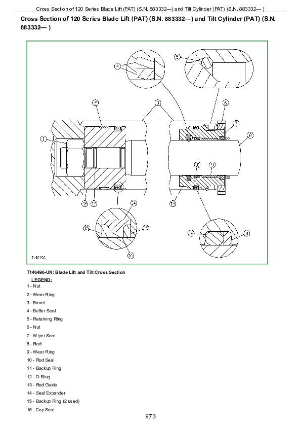
Cross Section of 120 Series Blade Lift (PAT) (S.N. 883332—) and Tilt Cylinder (PAT) (S.N. 883332— )
Assemble 120 Series Blade Tilt (PAT) (S.N. 883332—) and Lift Cylinder (PAT) (S.N. 883332— )
Disassemble 125 Series Blade Angle Cylinder (PAT) (S.N. 883332— )
Cross Section of 125 Series Blade Angle Cylinder (PAT) (S.N. 883332— )
Assemble 125 Series Blade Angle Cylinder (PAT) (S.N. 883332— )
Group 3299: Dealer Fabricated Tools
DFT1180 Cylinder Nut Torque Tool
Section 9900: Dealer Fabricated Tools
Group 0999: Dealer Fabricated Tools
DF1065 Final Drive and Pump Adapter Bracket
DFT1041 Track Nut Removal Tool
DFT1063 Final Drive Lift Bracket
DFT1132 Hydrostatic Motor Removal and Installation Tool
DFT1137 Hydrostatic Motor Removal and Installation Tool
DFT1167 Final Drive Lifting Bracket Adapter Spacer
DFT1243 Lifting Bracket Extension
DFT1250 Lifting Bracket
DFT1260 Final Drive Lifting Fixture
DFT1261 Rolling Torque Measurement Tool
John Deere Crawler Dozers 750C, 850C, 750C Series II, 850C Series II Repair Service Manual (TM1589)
![]()