
John Deere Tractors 6215, 6515 Repair Service Manual (TM4645)
John Deere Tractors 6215, 6515 Repair Service Manual (TM4645)
tm4645 - 6215 and 6515 tractors repair Technical Manual.pdf
Complete Repair Service Technical Manual for John Deere Tractors 6215 and 6515 (European), with all the technical information to maintain, diagnose, repair, and rebuild like professional mechanics.
John Deere 2WD or MFWD - European Tractors models 6215 and 6515 workshop technical manual (repair) includes:
* Numbered table of contents easy to use so that you can find the information you need fast.
* Detailed sub-steps expand on repair procedure information
* Numbered instructions guide you through every repair procedure step by step.
* Notes, cautions and warnings throughout each chapter pinpoint critical information.
* Bold figure number help you quickly match illustrations with instructions.
* Detailed illustrations, drawings and photos guide you through every procedure.
* Enlarged inset helps you identify and examine parts in detail.
PRODUCT DETAILS:
Total Pages: 1,221 pages
File Format: PDF (bookmarked, ToC, Searchable, Printable, high quality)
Language: English
MAIN SECTIONS
Foreword
SAFETY
Safety Measures
GENERAL INFORMATION
Specifications
Tune-Up
Predelivery Inspection
ENGINE
Engine Removal and Installation
FUEL, AIR INTAKE, COOLING AND EXHAUST SYSTEMS
Speed Control Linkage
Fuel System
Air Intake System
Cooling System
Cold-Weather Starting Aids
Exhaust System
ELECTRICAL SYSTEM
Connectors
Wiring Harnesses
Charging Circuit
Starting Motor Circuit
Fuses, Relays and Switches
Monitoring Systems
Electrical Components
SYNCROPLUS TRANSMISSION
Removal and Installation of Transmission Components
Transmission Shift Controls
Perma Clutch II Module
Gear Transmission
POWER REVERSER TRANSMISSION
Removal and Installation of Transmission Components
Transmission Shift Controls
Power Reverser Module
Gear Transmission
Range Transmission
DRIVE SYSTEMS
Removal and Installation of Components
U-Jointed Shafts and Torsion Damper
Front-Wheel Drive Clutch
Differential
Hydraulic Pump Drive
Final Drives
Rear PTO
STEERING AND BRAKES
Hydrostatic Steering
Steering Cylinder
Brake Valve
Rear Brakes
Handbrake
Hydraulic Trailer Brake
HYDRAULIC SYSTEM
Controls
Hydraulic Pump
Valves
Rockshaft
Selective Control Valves and Couplers
MISCELLANEOUS
Removal and Installation of Components
Main Frame
Front Axle
Front Wheels, Rear Wheels and Fenders
Trailer Hitch and Swinging Drawbar
OPERATOR'S STATION
Removal and Installation of Components
Controls and Instruments
2-post ROPS
Operator's Seat
SPECIAL TOOLS
Special Tools (Dealer-Fabricated)
Special Tools and Test Equipment
tm4645 - 6215 and 6515 tractors repair - Table of Contents
Foreword
Section 05: SAFETY
Group 05: Safety Measures
Recognize Safety Information
”Important” Information
”Note” Information
Prevent Machine Runaway
Handle Fluids Safely-Avoid Fires
Prevent Battery Explosions
Prepare for Emergencies
Prevent Acid Burns
Avoid High-Pressure Fluids
Service Cooling System Safely
Remove Paint Before Welding or Heating
Avoid Heating Near Pressurized Fluid Lines
Work In Ventilated Area
Wear Protective Clothing
Practice Safe Maintenance
Park Machine Safely
Use Proper Lifting Equipment
Construct Dealer-Made Tools Safely
Support Machine Properly
Work in Clean Area
Illuminate Work Area Safely
Service Machines Safely
Use Proper Tools
Service Tires Safely
Service Front-Wheel Drive Tractor Safely
Safety Information - Air Brake System
Avoid Eye Contact With Radar
Keep ROPS Installed Properly
Replace Safety Signs
Dispose of Waste Properly
Live With Safety
Safety Measures on Electronic Control Units
Section 10: GENERAL INFORMATION
Group 05: Specifications
References, Specifications
Engine Specifications
Cooling System
Lucas/Stanadyne Fuel Injection Pump
Level 12 Electronic Fuel System With Stanadyne DE10 Pump
Air Intake System
Electrical System
Hydrostatic Steering System
Clutch
SyncroPlus Transmission
Power Reverser
Rear PTO
Differential assembly
Differential lock
Final drives
Front-Wheel Drive
Hydraulic Brakes
Handbrake
Parking Lock
Hydraulic System with Gear-Driven Pump
Rockshaft
Ground Speeds
Front and Rear Wheels
Dimensions and Weights
Capacities
Handling and Storing Diesel Fuel
Diesel Fuel
Lubricity of Diesel Fuel
Diesel Engine Break-In Oil
Diesel Engine Oil (Engine Serial Number up to 799999)
Diesel Engine Oil (Engine Serial Number from 800000)
Transmission and Hydraulic Oil
Front-Wheel Drive Axle Oil
Diesel Engine Coolant
Supplemental Coolant Additives
Grease
Oil Filters
Mixing of Lubricants
Lubricant Storage
Operating in Warm Temperature Climates
Alternative and Synthetic Lubricants
Unified Inch Bolt and Screw Torque Values
Metric Bolt and Screw Torque Values
Hydraulic system inch fitting torques
Hydraulic system metric fitting torques
Product Identification and Sub-Assembly Serial Numbers
Engine serial number
Transmission serial number
Front wheel drive axle serial number
Operator's Seat Serial Number
Sub-assembly serial numbers
Group 10: Tune-Up
General References, Tune-Up
Specifications
Using High-Pressure Washers
Preliminary Engine Test
Tractor Tune-Up
Removing and Cleaning the Primary Air Cleaner Element
Checking the Air Cleaner Safety Element
Installing the Primary Filter Element
Checking the Air Intake System Connections for Leaks
Checking the Crankcase Vent Hose for Clogging
Cleaning the Radiator Grille Screen
Keeping the Radiator Screen Clean
Checking the Caps on the Expansion Tank
Checking the Radiator for Leaks
Checking the Engine Thermostat
Check Fuel Transfer Pump Operation
Checking the Fuel Filter
Checking the Fuel Filter (With Denso/Stanadyne Injection Pump; Stage II Engines according to 97/68/EC)
Bleed Fuel System
Clean the water trap
Run the engine until it is warm, and check engine speeds
Check setting of fuel injection pump
Check setting of speed control linkage
Cleaning the Battery, Cables and Battery Box with a Clean Cloth
Check Neutral Start Circuit
Check operation of starting motor
Checking the lighting circuit
Final Engine Check
Tractor Operation Check
Group 15: Predelivery Inspection
Predelivery Inspection
Section 20: ENGINE
Group 00: Engine Removal and Installation
Special or Essential Tools
Specifications
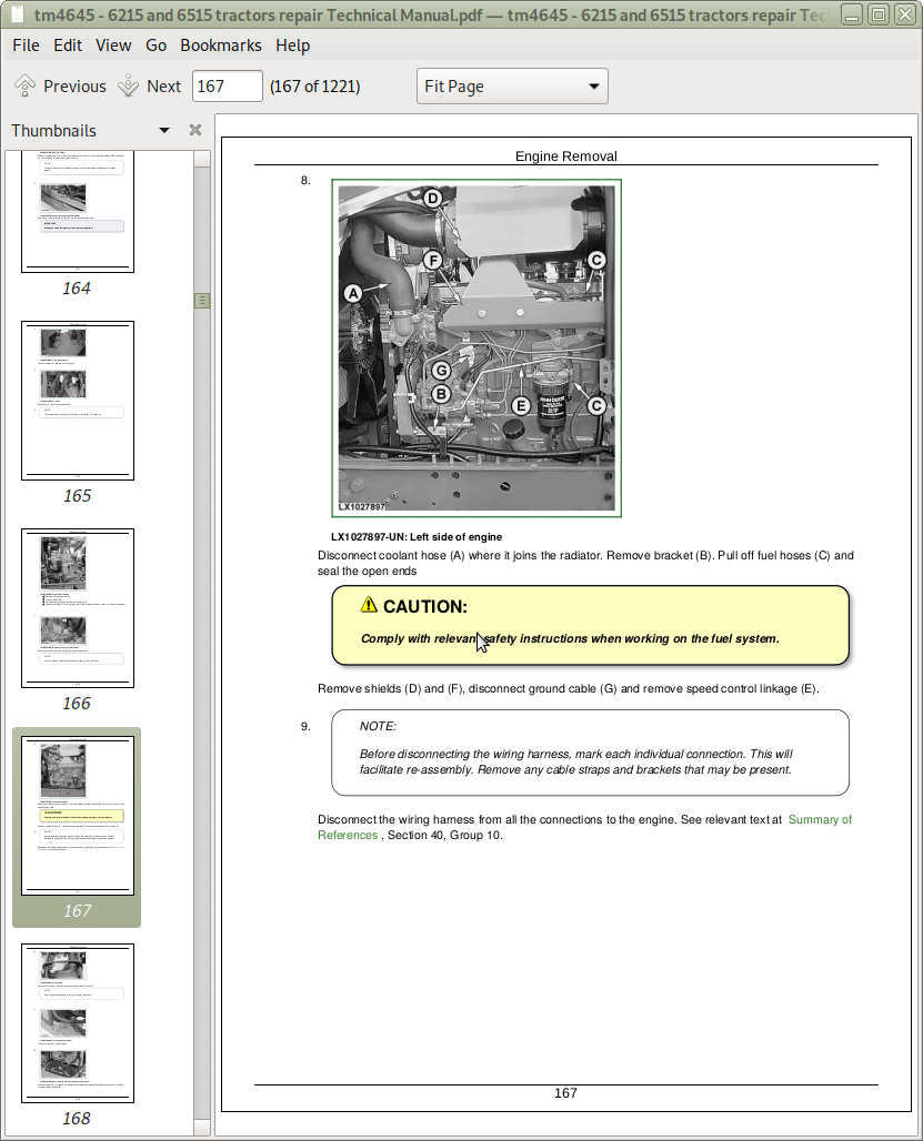
Engine Removal
Engine Installation
Section 30: FUEL, AIR INTAKE, COOLING AND EXHAUST SYSTEMS
Group 05: Speed Control Linkage
Speed Control (Summary of References)
General Information
Specifications
Adjusting the Speed Control Linkage
Hand Throttle Lever - Exploded View
Adjustment of Hand Throttle Lever
Adjustment of Hand Throttle Lever and Accelerator Pedal
Accelerator Pedal - Exploded View
Hand Throttle Lever, with Electronic Speed Control ("Cruise Control")
Accelerator Pedal, With Electronic Speed Control (”Cruise Control”)
Group 10: Fuel System
Fuel System (Summary of References)
General Information
Special Tool (Dealer-Fabricated)
Remove Fuel Tank
Installing the Fuel Tank
Replace Fuel Gauge Sending Unit
Replace Fuel Transfer Pump
Replace Fuel Filter
Bleeding the Fuel System
Bleed the Air from the Fuel System (with Denso/Stanadyne Injection Pump)
Install Check Valve in Fuel System
Group 15: Air Intake System
Air Intake System (Summary of References)
General Information
Air filter - Exploded view
Replacing the Sending Unit for Air Cleaner Restriction (B02)
Air Intake System
Group 20: Cooling System
Cooling System (Summary of References)
General Information
Specifications
Removing and Installing the Ring-Shaped Cooler
Remove the Radiator
Change the Fan or the Viscous Fan Drive
Remove and Install the Intercooler
Removing and Installing the Expansion Tank
Removing and Installing the Thermostat Valve
Installing the Radiator
Filling the Cooling System with Coolant
Relieving Tension on the Drive Belt
Replace Drive Belt
Replacing the Drive Belt Tensioner
Repairing the Fan Console
Group 25: Cold-Weather Starting Aids
Fuel Preheater
Electrical Starting Aid
Coolant Heater
Group 30: Exhaust System
Exhaust System (Summary of References)
General Information
Specifications
Exhaust to Top Right
Section 40: ELECTRICAL SYSTEM
Group 05: Connectors
Special Tools
General
Using high-pressure washers
Disconnecting electrical circuits
Stripping Wire Ends
Terminal Installation
METRI PACK Connector with Terminal Lock at the Rear
METRI PACK Connectors
Connectors for Electronic Control Units
Connectors
DEUTSCH Connectors
Individual Terminals
Fuse and Relay Box
Group 10: Wiring Harnesses
Wiring Harnesses for Tractors without Engine Control Unit - Repair (Summary of References)
Wiring Harnesses for Tractors with Engine Control Unit (Level 12 ECU) - Reconditioning (Summary of References)
Wiring Harnesses for Tractors with Engine Control Unit (Level 12 ECU) and Noise Reduction - Reconditoning (Summary of References)
Disconnecting electrical circuits
Ground Point Locations
Remove and Install Harness W01 - Power Supply
Remove and Install Harness W02 - Engine for Tractors without Engine Control Unit
Remove and Install Harness W02 - Engine, for Tractors with Engine Control Unit (ECU Level 12)
Remove and Install Harness W03 - Starting Aid up to Serial No. 437019
Remove and Install Harness W03 - Starting Aid from Serial No. 437020
Remove and Install Harness W04 - Headlights
Remove and Install Harness W05 - Front Corner Worklights
Remove and Install Harness W08 - Open Operator's Station, for Tractors without Engine Control Unit
Remove and Install Harness W08 - Open Operator's Station, for Tractors with Engine Control Unit (Level 12 ECU)
Remove and Install Harness W09 - Cowl, for Tractors without Engine Control Unit
Remove and Install Harness W09 - Cowl, for Tractors with Engine Control Unit (ECU Level 12)
Remove and Install Harness W14 - 3-Terminal Power Outlet Socket
Remove and Install Harness W28 - Front End of Transmission
Remove and Install Harness W30 - Rear End of Transmission
Remove and Install Harness W30 - Rear End of Transmission (Tractors with Noise Reduction)
Remove and Install Harness W31 - 7-Terminal Power Outlet Socket
Group 15: Charging Circuit
Special Tools
Specifications
Repairing the Alternator
Disconnecting Electrical Circuits
Relieve Drive Belt Tension
Remove/Install the Alternator
Pulley Removal and Installation
Group 20: Starting Motor Circuit
Special or Essential Tools
Specifications
Repairing the Starter Motor
Disconnecting Electrical Circuits
Remove and Install Starting Motor
Group 25: Fuses, Relays and Switches
General Information
Specifications
Fuses, Relays and Switches - Repair (Summary of References)
Remove Trim Panels from Cowl
Disconnecting electrical circuits
Fuse and Relay Box
Replace Main Fuses
Replace Electric Starting Aid Fuses
Replace Starting Motor Relay
Replace Electric Starting Aid Relay
Replace Main Switch
Replace Brake Switches
Replace Light Switch
Replace Full/Dipped-Beam Switch
Replace Work Light Switch
Replace Hazard Warning Light Switch
Replace Turn Signal Switch
Replace Horn Switch
Replace Handbrake Switch
Replace Front-Wheel Drive Switch
Replace Differential Lock Switch.
Group 30: Monitoring Systems
General Information
Information for Tractors with Stage II Engine to 97/68/EC (Level 12 ECU)
Monitoring Systems - Repair (Summary of References)
Disconnecting electrical circuits
Replace Engine Speed Sending Unit (B01)
Replace Engine Oil Pressure Sending Unit (B04)
Replace Coolant Temperature Gauge Sending Unit (B08)
Replace Turn Signal Flasher
Group 40: Electrical Components
General Information
Special or Essential Tools
Electrical Components - Repair (Summary of References)
Disconnecting electrical circuits
Replace 7-Terminal Power Outlet Socket
Replace 3-Terminal Power Outlet Socket
Replace Service Socket
Adjusting the Headlights
Safety Instructions for Replacing a Halogen Bulb
Section 50: SYNCROPLUS TRANSMISSION
Group 00: Removal and Installation of Transmission Components
Special or Essential Tools
Specifications
Remove Clutch Housing
Install Clutch Housing
Gear Transmission Removal and Installation
Group 05: Transmission Shift Controls
SyncroPlus Transmission Shift Units - Reconditioning (Summary of References)
Specifications
Remove Shift Unit for Gear and Range Transmissions
Recondition the Shift Unit for Gear and Range Transmissions
Install Shift Unit for Gear and Range Transmissions
Check Shift Units
Gear Shift Linkage Adjustment
Range Shift Linkage Adjustment
Park Lock Adjustment
Clutch Pedal Adjustment
Group 10: Perma Clutch II Module
SyncroPlus Transmission, Perma Clutch II Module - Reconditioning (Summary of References)
Special or Essential Tools
Specifications
Removing the Clutch
Reconditioning the Clutch
Installing the Clutch
Removing the Transmission Oil Pump
Reconditioning the Transmission Oil Pump
Installing the Transmission Oil Pump
Valves and Other Hydraulic Components
Reconditioning the Engagement Override Valve
Reconditioning the Clutch Cooling Valve
Reconditioning the Cooling Pilot Valve
Reconditioning the Filter Relief Valve
Repair of Pressure Regulating Valve
Reconditioning the Lube Relief Valve
Reconditioning the Cooler Relief Valve
Reconditioning the Clutch Pedal Valve
Replace Temperature and Pressure Sending Units
Group 15: Gear Transmission
SyncroPlus Transmission, Gear Transmission - Reconditioning (Summary of References)
Special or Essential Tools
Specifications
Gear Transmission - Sectional View
Disassembly of Gear Transmission
Reconditioning the Gear Transmission
Preparation for Installing the Gear Transmission
Repair of Shift Cover
Adjusting the Gear Transmission Shift Mechanism
Neutral Start Switch, Adjustment
Section 51: POWER REVERSER TRANSMISSION
Group 00: Removal and Installation of Transmission Components
Special Tools
Specifications
Remove Power Reverser Module
Install Power Reverser Module
Remove Gear Transmission
Install Gear Transmission
Remove Range Transmission
Install Range Transmission
Group 05: Transmission Shift Controls
Power Reverser Shift Units - Reconditioning (Summary of References)
Specifications
Remove Shift Unit for Gear and Range Transmissions
Recondition the Shift Unit for Gear and Range Transmissions
Install Shift Unit for Gear and Range Transmissions
Check Shift Units
Gear Shift Linkage Adjustment
Range Shift Linkage Adjustment
Park Lock Adjustment
Repair of Forward/Reverse Control
Reverse Drive Lever Adjustment
Adjust Reverse Drive Linkage
Clutch Pedal Adjustment
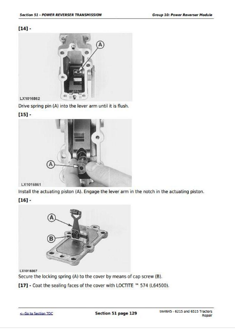
Group 10: Power Reverser Module
Power Reverser Transmission, Power Reverser Module - Reconditioning (Summary of References)
Special or Essential Tools
Specifications
Power Reverser Module - Sectional View
Components of Power Train
Removing the Disk Brake
Reconditioning the Disk Brake
Installing the Disk Brake
Removing the Clutch and Planetary Carrier
Reconditioning the Clutch and Planetary Carrier
Installing the Clutch and Planetary Carrier
Removing the Transmission Oil Pump
Reconditioning the Transmission Oil Pump
Installing the Transmission Oil Pump
Valves and Other Hydraulic Components
Repair of Pressure Regulating Valve
Reconditioning the Cooling Pilot Valve
Reconditioning the Clutch Cooling Valve
Reconditioning the Engagement Override Valve
Reconditioning the Filter Relief Valve
Reconditioning the Cooler Relief Valve
Reconditioning the Lube Relief Valve
Reconditioning the Sump Valve
Reconditioning the Accumulator Piston
Reconditioning the Forward/Reverse Valve
Reconditioning the Fwd/Rev Cooling Control Valve
Reconditioning the Modulator Valve
Reconditioning the Connecting Valve
Reconditioning the Clutch Pedal Valve
Replace Temperature and Pressure Sending Units
Replacing the Oil Filter
Replacing the Neutral Start Switch
Group 15: Gear Transmission
Power Reverser Transmission, Gear Transmission - Reconditioning (Summary of References)
Special or Essential Tools
Specifications
Gear Transmission - Sectional View
Disassembly of Gear Transmission
Exploded View of Gear Transmission
Gear Transmission Repair
Preparation for Installing the Gear Transmission
Repair of Shift Cover
Adjust Shift Mechanism on Gear Transmission
Group 20: Range Transmission
Range Transmission - Reconditioning (Summary of References)
Specifications
Range Transmission - Sectional View
Remove Range Transmission
Disassembly of Range Transmission
Exploded View of Differential Drive Shaft
Assembly of Differential Drive Shaft
Install Drive Shaft and Adjust Cone Point
Exploded View of Drive Shaft and Park Lock
Exploded View of Range Shift Linkage
Assembly of Range Transmission
Install Range Transmission
Measure Play at Drive Shaft
Range Shift Linkage Adjustment
Repair of Shift Cover
Section 56: DRIVE SYSTEMS
Group 00: Removal and Installation of Components
Special Tools
Specifications
Removing the FWD Clutch
Installing the FWD Clutch
Remove Differential Housing
Install Differential Housing
Remove Final Drives
Install Final Drives
Remove Rear PTO
Install Rear PTO
Group 05: U-Jointed Shafts and Torsion Damper
Summary of References (U-Jointed Shafts and Torsion Damper)
Specifications
Remove U.J. Shaft (Front-Wheel Drive)
Reconditioning the U.j. Shaft (FWD)
Install U.J. Shaft (Front-Wheel Drive)
Remove Engine U.J. Shaft
Remove and Install Ring-Shaped Cooler
Remove Torsion Damper
Changing the Torsion Damper Bearings
Installing the Torsion Damper
Install Engine U.J. Shaft
Group 10: Front-Wheel Drive Clutch
Front-Wheel Drive Clutch - Repair (Summary of References)
Special Tools
Other Material
Specifications
Disassemble Front-Wheel Drive Clutch
Front-Wheel Drive Clutch - Exploded View
Assemble Front-Wheel Drive Clutch
Group 15: Differential
Differential - Reconditioning (Summary of References)
Specifications
Remove Differential
Disassembly of Differential
Differential - Exploded View
Assembly of Differential
Installing the Differential
Group 20: Hydraulic Pump Drive
Specifications
Repair of Hydraulic Pump Drive
Adjustment of Hydraulic Pump Drive
Group 25: Final Drives
Special or Essential Tools
Specifications
Repair of Final Drives
Group 30: Rear PTO
Rear PTO - Summary of References
Special Tools
Dealer-Fabricated Special Tools
Other Material
Specifications
Replace Output Shaft Seal Ring
Changing the O-Ring on Reversible PTO
Remove PTO Clutch
Repair of PTO Clutch
Install PTO Clutch
Repair of PTO Brake
Disassembly of PTO Drive Train
Repair of Output Shaft (540 rpm)
Repair of Output Shaft and Countershaft (540/1000 rpm, reversible)
Assemble PTO Drive Train
Rear PTO - Install Support and Adjust Taper Roller Bearings
Rear PTO - Remove PTO Modulating Valve
Rear PTO - Repair of PTO Modulating Valve
Rear PTO - Install PTO Modulating Valve
Section 60: STEERING AND BRAKES
Group 05: Hydrostatic Steering
Hydrostatic Steering (Summary of References)
Special Tools
Specifications
Preliminary Work
Disconnecting/Connecting Steering or Brake Hoses
Steering Valve - Removal
Disassembling the Steering Valve
Exploded View of Steering Valve
Assembling the Steering Valve
Adjusting the Shock Valves
Steering Valve - Installation
Group 10: Steering Cylinder
Steering Cylinder (Summary of References)
General Information
Special or Essential Tools
Specifications
Repair Information
Remove Steering Cylinder
Repair of Steering Cylinder
Assemble Steering Cylinder
Install Steering Cylinder
Install Front Axle
Group 15: Brake Valve
Summary of References (Brake Valve)
Special Tools
Repair Information
Specifications
Preliminary Work
Remove Brake Valve
Disassemble Brake Valve
Exploded View of Brake Valve
Assemble Brake Valve
Install Brake Valve
Adjust Brake Pedals
Adjust Brake Switches
Final Assembly
Group 20: Rear Brakes
Summary of References (Rear Brakes)
Special or Essential Tools
Specifications
Remove Rear Brakes
Install Rear Brake
Check Brake Pistons for Return Movement and Leakage
Final assembly
Bleed the Brakes (Brake Valve Without Power Fill)
Group 25: Handbrake
Handbrake (Summary of References)
Specifications
Preliminary Work
Remove Handbrake
Handbrake - Exploded View
Install Handbrake
Final Assembly
Handbrake Components
Replace Handbrake Cable
Handbrake Test
Adjust Handbrake
Group 30: Hydraulic Trailer Brake
Hydraulic Trailer Brake (Summary of References)
Special Tools
Specifications
Repair Instructions
Change Trailer Brake Valve
Clean Trailer Brake Valve
Clean the Screen
Bleeding the Trailer Brake Valve
Check Hydraulic Trailer Brake Valve
Adjust Hydraulic Trailer Brake Valve
Section 70: HYDRAULIC SYSTEM
Group 05: Controls
Rockshaft Valve - Remove and Install Control Lever
Selective Control Valves - Remove and Install Control Lever
Group 10: Hydraulic Pump
Other Material
Specifications
Remove Hydraulic Pump
Hydraulic Pump - Remove Installation Plate
Replace Lube Priority Valve
Hydraulic Pump - Install Installation Plate
Install Hydraulic Pump
Group 15: Valves
Repair of Hydraulic System Valves - Summary of References
Other Material
Specifications
Hydraulic System - General Instructions on Safety and Repair
Repair of Priority Valve
Remove Rockshaft Valve
Rockshaft Valve - Remove Control Valve
Rockshaft Valve - Repair of Control Valve
Rockshaft Valve - Install Control Valve
Rockshaft Valve - Remove and Install Control Lever Console
Rockshaft Valve - Repair of Regulating Components
Install Rockshaft Valve
Recondition the Hydraulic Oil Filter
Group 20: Rockshaft
Specifications
Rockshaft - Remove and Install Rockshaft
Rockshaft - Remove Rockshaft Cylinders
Rockshaft - Reconditioning the Rockshaft Cylinders
Rockshaft - Install Rockshaft Cylinders
Remove Center Link Support
Repair of Center Link Support
Install Center Link Support
Group 25: Selective Control Valves and Couplers
Repair of Selective Control Valves and Couplers - Summary of References
Other Material
Specifications
Remove Selective Control Valves
Repair Selective Control Valves Without Float Position
Repair Selective Control Valves With Float Position
Selective Control Valves - Repair of Inlet Plate
Selective Control Valves - Repair of Outlet Plate
Install Selective Control Valves
Selective Control Valves - Repair of Couplers
Section 80: MISCELLANEOUS
Group 00: Removal and Installation of Components
Special or Essential Tools
Specifications
Removing and Installing the Main Frame (Summary of References)
Remove Main Frame
Install Main Frame
Remove and Install Front Axle or Front-Wheel Drive Axle (Summary of References)
Remove the Front Axle
Install Front Axle
Remove Front-Wheel Drive Axle
Install Front-Wheel Drive Axle
Remove Front Axle Support
Install Front Axle Support
Group 05: Main Frame
Specifications
Repair of Main Frame (Tractors with 4-Cylinder Engines)
Repair of Main Frame (Tractors with 6-Cylinder Engines)
Group 10: Front Axle
Specifications
Front Axle - Repair (Summary of References)
Remove and Install Front Axle
Repair of Wheel Hub
Adjust Wheel Bearings
Repair of Knuckle and Spindle Assy.
Adjust Axial Play at the Knuckle and Spindle Assy.
Repair Axle Center Section and Support
Check and Adjust Toe-In
Group 15: Front Wheels, Rear Wheels and Fenders
Front Wheels, Rear Wheels and Fenders - Reconditioning (Summary of References)
Special Tools
Specifications
Pivoting Front Fender
Remove and Install Front Wheels
Remove and Install Rear Wheels
Repair of Front Wheel Rims
Repair of Rear Wheel Rims
Group 20: Trailer Hitch and Swinging Drawbar
Specifications
Install Support for Center Link
Reconditioning the height-adjustable trailer hitch (Italy and Spain only)
Swinging Drawbar
Adjusting the Retaining Strap
Section 90: OPERATOR'S STATION
Group 00: Removal and Installation of Components
Specifications
Remove Open Operator's Station
Install Open Operator's Station
Check and Adjust Shift Mechanisms/Linkages
Group 05: Controls and Instruments
Summary of References (Controls and Instruments)
Preliminary Work
Instructions when Replacing a Control Unit
Replace Bulbs on the Instrument Unit
Replace Control Unit (ECU)
Group 15: 2-post ROPS
2-Post ROPS (Summary of References)
Keep ROPS Installed Properly
Specifications
Torques for Hardware on Platform Mounting (with 2-Post ROPS)
Torques for Hardware on Platform Mounting (without 2-Post ROPS)
Group 20: Operator's Seat
Operator's Seat (Summary of References)
Specifications
Replace Lap-Strap (Left-Hand Side)
Replace Lap-Strap (Right-Hand Side)
Attach Operator's Seat
Exploded View of Comfort Seat MSG44
Section 99: SPECIAL TOOLS
Group 05: Special Tools (Dealer-Fabricated)
DFLX2 - Suspension Device
DFLX13 - Holding Device
Holding Tool
DFLX16 - Wooden Block
DFLX24 - Seal Installer
DFLX26 - Extraction Tool
DFLX17 - Assembly and Guide Mandrels
Turning Device
Bushing
DFLX21 - Special Wrench
Group 10: Special Tools and Test Equipment
KJD10168 - Ring Nut Socket
![]()