
John Deere 220DW Wheeled Excavator Service Manual (Operation & Test - TM10544)
Complete Operation & Test manual with Electrical Wiring Diagrams for John Deere 220DW Wheeled Excavator, with all the shop information to maintain, diagnose, and rebuild like professional mechanics.
John Deere 220DW Wheeled Excavator workshop service manual includes:
* Numbered table of contents easy to use so that you can find the information you need fast.
* Detailed sub-steps expand on repair procedure information
* Numbered instructions guide you through every repair procedure step by step.
* Troubleshooting and electrical service procedures are combined with detailed wiring diagrams for ease of use.
* Notes, cautions and warnings throughout each chapter pinpoint critical information.
* Bold figure number help you quickly match illustrations with instructions.
* Detailed illustrations, drawings and photos guide you through every procedure.
* Enlarged inset helps you identify and examine parts in detail.
TM10544 - John Deere 220DW Wheeled Excavator Technical Manual (Operation & Test).PDF
TM10544 - John Deere 220DW Wheeled Excavator Technical Manual (Operation & Test).EPUB
Total Pages: 1,835 pages
File Format: PDF (bookmarked, Searchable, Printable, high quality)
Language: English
TABLE OF CONTENTS....1
Section 9000: General Information....23
Group 01: Safety....23
Recognize Safety Information....26
Follow Safety Instructions....27
Operate Only If Qualified....28
Wear Protective Equipment....29
Avoid Unauthorized Machine Modifications....30
Add Cab Guarding for Special Uses....31
Inspect Machine....32
Stay Clear of Moving Parts....33
Avoid High-Pressure Fluids....34
Avoid High-Pressure Oils....35
Beware of Exhaust Fumes....36
Prevent Fires....37
Prevent Battery Explosions....38
Handle Chemical Products Safely....39
Dispose of Waste Properly....40
Prepare for Emergencies....41
Use Steps and Handholds Correctly....42
Start Only From Operator's Seat....43
Use and Maintain Seat Belt....44
Prevent Unintended Machine Movement....45
Avoid Work Site Hazards....46
Keep Riders Off Machine....48
Avoid Backover Accidents....49
Avoid Machine Tip Over....50
Use Special Care When Lifting Objects....51
Add and Operate Attachments Safely....52
Park and Prepare for Service Safely....53
Service Cooling System Safely....54
Remove Paint Before Welding or Heating....55
Service Tires Safely....56
Make Welding Repairs Safely....57
Drive Metal Pins Safely....58
Section 9001: Diagnostic Trouble Codes (DTC)....59
Group 10: Main Controller (MCF) Diagnostic Trouble Codes....68
Main Controller (MCF) Diagnostic Trouble Codes....68
11000.02 - Abnormal EEPROM....59
11001.02 - Abnormal RAM....59
11002.02 - Abnormal A/D Conversion....59
11003.02 - Abnormal Sensor Voltage....59
11004.02 - Abnormal CAN Communication....59
11100.02 - Abnormal Engine Speed....59
11101.03 - Engine Control Dial Sensor Voltage High....59
11101.04 - Engine Control Dial Sensor Voltage Low....59
11200.03 - Pump 1 Delivery Pressure Sensor Voltage High....59
11200.04 - Pump 1 Delivery Pressure Sensor Voltage Low....59
11202.03 - Pump 2 Delivery Pressure Sensor Voltage High....59
11202.04 - Pump 2 Delivery Pressure Sensor Voltage Low....59
11203.03 - Steering Pump Delivery Pressure Sensor Voltage High....59
11203.04 - Steering Pump Delivery Pressure Sensor Voltage Low....59
11206.03 - Pump 1 Control Pressure Sensor Voltage High....59
11206.04 - Pump 1 Control Pressure Sensor Voltage Low....59
11208.03 - Pump 2 Control Pressure Sensor Voltage High....59
11208.04 - Pump 2 Control Pressure Sensor Voltage Low....59
11301.03 - Swing Pilot Pressure Sensor Voltage High....59
11301.04 - Swing Pilot Pressure Sensor Voltage Low....59
11302.03 - Boom-up Pilot Pressure Sensor Voltage High....59
11302.04 - Boom-up Pilot Pressure Sensor Voltage Low....59
11303.03 - Arm-in Pilot Pressure Sensor Voltage High....59
11303.04 - Arm-in Pilot Pressure Sensor Voltage Low....59
11305.03 - Travel Forward Pressure Sensor Voltage High....59
11305.04 - Travel Forward Pressure Sensor Voltage Low....59
11306.03 - Travel Reverse Pressure Sensor Voltage High....59
11306.04 - Travel Reverse Pressure Sensor Voltage Low....59
11307.03 - Front Attachment Pressure Sensor Voltage High....59
11307.04 - Front Attachment Pressure Sensor Voltage Low....59
11310.03 - Brake Pressure Sensor Voltage High....60
11310.04 - Brake Pressure Sensor Voltage Low....60
11311.03 - Brake Remaining Pressure Sensor Voltage High....60
11311.04 - Brake Remaining Pressure Sensor Voltage Low....60
11400.02 - Pump 2 Flow Rate Limit Solenoid Feedback Current Abnormal....60
11400.03 - Pump 2 Flow Rate Limit Solenoid Feedback Current High....60
11400.04 - Pump 2 Flow Rate Limit Solenoid Feedback Current Low....60
11401.02 - Torque Control Solenoid Feedback Current Abnormal....60
11401.03 - Torque Control Solenoid Feedback Current High....60
11401.04 - Torque Control Solenoid Feedback Current Low....60
11403.02 - Arm Regenerative Solenoid (SC) Feedback Current Abnormal....60
11403.03 - Arm Regenerative Solenoid (SC) Feedback Current High....60
11403.04 - Arm Regenerative Solenoid (SC) Feedback Current Low....60
11404.02 - Power Dig Solenoid (SG) Feedback Current Abnormal....60
11404.03 - Power Dig Solenoid (SG) Feedback Current High....60
11404.04 - Power Dig Solenoid (SG) Feedback Current Low....60
11410.02 - Pump 1 Flow Rate Limit Solenoid Feedback Current Abnormal....60
11410.03 - Pump 1 Flow Rate Limit Solenoid Feedback Current High....60
11410.04 - Pump 1 Flow Rate Limit Solenoid Feedback Current Low....60
11422.02 - Travel Speed Solenoid Feedback Current Abnormal....60
11422.03 - Travel Speed Solenoid Feedback Current High....60
11422.04 - Travel Speed Solenoid Feedback Current Low....60
11423.02 - Travel Make-up Solenoid Feedback Current Abnormal....60
11423.03 - Travel Make-up Solenoid Feedback Current High....60
11423.04 - Travel Make-up Solenoid Feedback Current Low....60
11424.02 - Axle Lock Solenoid (SI) Feedback Current Abnormal....60
11424.03 - Axle Lock Solenoid (SI) Feedback Current High....60
11424.04 - Axle Lock Solenoid (SI) Feedback Current Low....60
11425.02 - Work Brake Solenoid (SF) Feedback Current Abnormal....60
11425.03 - Work Brake Solenoid (SF) Feedback Current High....60
11425.04 - Work Brake Solenoid (SF) Feedback Current Low....60
11502.02 - Travel Motor Overspeed....60
11901.03 - Hydraulic Oil Temperature Sensor Voltage High....60
11901.04 - Hydraulic Oil Temperature Sensor Voltage Low....61
11910.02 - Engine Speed CAN Message Abnormal....61
11911.02 - Security Signal CAN Message Abnormal....61
11914.02 - Engine Coolant Temperature CAN Message Abnormal....61
11915.02 - Pilot Shutoff Signal CAN Message Abnormal....61
11918.02 - Work Mode CAN Message Abnormal....61
11920.02 - Fuel Flow Rate CAN Message Abnormal....61
11921.02 - Incorrect Odometer Value....61
Group 20: Engine Control Module (ECM) Diagnostic Trouble Codes....319
Engine Control Module (ECM) Diagnostic Trouble Codes....319
100.03 - Engine Oil Pressure Sensor Voltage Low (P0522)....61
100.04 - Engine Oil Pressure Sensor Voltage High (P0523)....61
102.03 - Boost Pressure Sensor Voltage Low (P0237)....61
102.04 - Boost Pressure Sensor Voltage High (P0238)....61
105.03 - Boost Temperature Sensor Voltage High (P1113)....61
105.04 - Boost Temperature Sensor Voltage Low (P1112)....61
108.03 - Barometric Pressure Sensor Voltage Low (P0107)....61
108.04 - Barometric Pressure Sensor Voltage High (P0108)....61
110.00 - Engine Coolant Temperature High (P1173)....61
110.03 - Engine Coolant Temperature Sensor Voltage High (P0118)....61
110.04 - Engine Coolant Temperature Sensor Voltage High (P0117)....61
157.00 - Fuel Rail Pressure Abnormal (First Stage) (P0088)....61
157.00 - Fuel Rail Pressure Abnormal (Second Stage) (P0088)....61
157.02 - Fuel Rail Pressure High (Pump Over-Pressure) (P0089)....61
157.03 - Fuel Rail Pressure Sensor Voltage High (P0193)....61
157.04 - Fuel Rail Pressure Sensor Voltage Low (P0192)....61
172.03 - Intake Air Temperature Sensor Voltage High (P0113)....61
172.04 - Intake Air Temperature Sensor Voltage Low (P0112)....61
174.03 - Fuel Temperature Sensor Voltage High (P0183)....61
174.04 - Fuel Temperature Sensor Voltage Low (P0182)....61
190.00 - Engine Overspeed (P0219)....61
628.02 - Abnormal ROM (P1603)....61
633.07 - Pressure Limiter Open (P1095)....61
636.02 - Abnormal Cam Angle Sensor (No Signal) (P0340)....62
636.02 - Abnormal Cam Angle Sensor (Abnormal Signal) (P0341)....62
636.07 - Phase Mismatch of Cam Angle Sensor (P1345)....62
639.02 - CAN Communication Error (U2104)....62
639.03 - CAN Time Out (U2106)....62
651.03 - Injector 1 Drive System Open Circuit (P0201)....62
652.03 - Injector 2 Drive System Open Circuit (P0202)....62
653.03 - Injector 3 Drive System Open Circuit (P0203)....62
654.03 - Injector 4 Drive System Open Circuit (P0204)....62
723.02 - Abnormal Crank Speed Sensor (No Signal) (P0335)....62
723.02 - Abnormal Crank Speed Sensor (Abnormal Signal) (P0336)....62
987.03 - Abnormal Check Engine Lamp (P0650)....62
1077.02 - Abnormal IC for CPU Watching (P0601)....62
1079.02 - 5 Volt Power Source 1 Voltage Abnormal (P1632)....62
1080.02 - 5 Volt Power Source 2 Voltage Abnormal (P1633)....62
1239.01 - No Pressure To Pump (P0087)....62
1240.01 - No Pressure To Pump (P1093)....62
1347.00 - Suction Control Valve Drive Circuit Open or Shorted (P0090)....62
1381.03 - High Voltage Fault of Fuel Differential Pressure Sensor....62
1381.04 - Low Voltage Fault of Fuel Differential Pressure Sensor....62
1485.02 - Engine Control Module (ECM) Relay Abnormal (P1625)....62
10001.03 - Abnormal EGR Position (P0487)....62
10002.02 - Abnormal EGR Valve Control (P0488)....62
10003.02 - Injector Drive System Common 1 Abnormal (P1262)....62
10004.02 - Injector Drive System Common 2 Abnormal (P1262)....62
10005.01 - Charge Circuit Abnormal Bank 1 (P0611)....62
10006.01 - Charge Circuit Abnormal Bank 2 (P0612)....62
10007.02 - Abnormal CPU (P0606)....62
10008.02 - Abnormal A/D Conversion (P1630)....62
10009.02 - 5 Volt Power Source 3 Voltage Abnormal (P1634)....62
10010.02 - 5 Volt Power Source 4 Voltage Abnormal (P1635)....62
10011.02 - 5 Volt Power Source 5 Voltage Abnormal (P1261)....62
10013.02 - Abnormal EEPROM (P1631)....62
Group 30: Information Controller (ICF) Diagnostic Trouble Codes....377
Information Controller (ICF) Diagnostic Trouble Codes....377
14000.02 - Abnormal CAN Communication....63
14001.02 - Flash Memory: Read / Write Error....63
14002.02 - External RAM: Read / Write Error....63
14003.02 - EEPROM: Sum Check Error....63
14006.02 - Satellite Communication Terminal: Communication Error....63
14008.02 - Abnormal Internal RAM....63
14100.02 - Satellite Communication Terminal: Abnormal EEPROM....63
14101.02 - Satellite Communication Terminal: Abnormal IB/OB Queue....63
14102.02 - Satellite Communication Terminal: Abnormal Local Loop Back....63
14103.02 - Satellite Communication Terminal: Satellite Cannot Be Found....63
14104.02 - Satellite Communication Terminal: Remote Loop Back Failure 1....63
14105.02 - Satellite Communication Terminal: Remote Loop Back Failure 2....63
14106.02 - Satellite Communication Terminal: Received Data is Not Same With Sent Data....63
Group 40: Air Conditioner Controller (ACF) Diagnostic Trouble Codes....417
Air Conditioner Controller (ACF) Diagnostic Trouble Codes....417
21 - Mix Door Open Circuit....63
Section 9005: Operational Checkout Procedure....773
Group 10: Operational Checkout Procedure....773
Operational Checkout....835
Section 9010: Engine....896
Group 05: Theory of Operation....896
Engine Component Location....899
Engine Fuel System Operation....900
Cooling System Operation....906
Engine Lubrication System Operation....908
Engine Intake and Exhaust System Operation....910
Engine Turbocharger Operation....911
Exhaust Gas Recirculation (EGR) Operation....912
Quick On System Operation....914
Engine Speed Control System Operation....915
Group 15: Diagnostic Information....896
4HK1 Isuzu Diesel Engine....922
Diagnose Engine Malfunctions....923
Engine Cranks But Will Not Start....896
Engine Misfires Or Runs Irregularly....896
Engine Does Not Develop Full Power....896
Engine Overheats....896
Auto-Idle Does Not Work....896
Coolant Temperature Too Low....896
Coolant in Oil or Oil in Coolant....896
Low Engine Oil Pressure....896
High Engine Oil Pressure....896
Engine Uses Too Much Oil....896
Engine Uses Too Much Fuel....896
Engine Emits Excessive Black or Gray Exhaust Smoke....896
Engine Emits Excessive White Exhaust Smoke....896
Turbocharger Excessively Noisy or Vibrates....896
Oil Dripping From Turbocharger Adapter....896
Excessive Drag in Turbocharger Rotating Members....896
Fuel In Oil....896
Engine Speed Can Not Be Controlled With Travel Pedal (Travel Pedal Engine Speed Control)....896
Group 25: Tests....897
Serpentine Belt Check and Adjust....974
High Pressure Fuel Pump Timing Check....976
Engine Valve Lash (Clearance) Check and Adjust....978
Engine Compression Pressure Test....982
Air Filter Restriction Indicator Switch Test....984
Engine Power Test Using Turbocharger Boost Pressure....986
Engine Oil Pressure Test....990
Section 9015: Electrical System....992
Group 05: System Information....992
Electrical Diagram Information....1003
Group 10: System Diagrams....992
Explanation of Wire Markings....1010
Fuse and Relay Specifications....1011
System Functional Schematic, Component Location, and Wiring Diagram Master Legend....1014
System Functional Schematic....1024
Cab Harness (W1) Component Location....1036
Cab Harness (W1) Wiring Diagram....1040
Machine Harness (W2) Component Location....1046
Machine Harness (W2) Wiring Diagram....1048
Monitor Harness (W3) Component Location....1051
Monitor Harness (W3) Wiring Diagram....1053
Engine Harness (W4) Component Location....1054
Engine Harness (W4) Wiring Diagram....1055
Floor Harness (W5) Component Location....1056
Floor Harness (W5) Wiring Diagram....1058
Chassis Harness (W6) Component Location....1059
Chassis Harness (W6) Wiring Diagram....1061
Right Console Harness (W7) Component Location....1063
Right Console Harness (W7) Wiring Diagram....1065
Pump Harness (W8) Component Location....1066
Pump Harness (W8) Wiring Diagram....1068
Left Console Harness (W9) Component Location....1069
Left Console Harness (W9) Wiring Diagram....1070
Air Suspension Seat Harness (W10) Component Location....1072
Air Suspension Seat Harness (W10) Wiring Diagram....1074
Right Pilot Control Lever Harness (W11) Component Location....1075
Right Pilot Control Lever Harness (W11) Wiring Diagram....1076
Swing Park Brake Solenoid Harness (W12) Component Location....1077
Swing Park Brake Solenoid Harness (W12) Wiring Diagram....1079
Blade and/or Outrigger Control Lever Harness (W13) Component Location....1080
Blade and/or Outrigger Control Lever Harness (W13) Wiring Diagram....1081
Boom Positioning and/or Assist Pressure Sensor Harness (W14) Component Location....1082
Boom Positioning and/or Assist Pressure Sensor Harness (W14) Wiring Diagram....1083
Power Dig Harness (W16) Component Location....1084
Power Dig Harness (W16) Wiring Diagram....1085
Digital Assist Harness (W17) Component Location—If Equipped....1086
Digital Assist Harness (W17) Wiring Diagram—If Equipped....1087
Digital or Analog Assist Solenoid Harness (W18) Component Location....1088
Digital or Analog Assist Solenoid Harness (W18) Wiring Diagram....1089
Cab Light Timer Harness (W19) Component Location....1090
Cab Light Timer Harness (W19) Wiring Diagram....1092
Boom Positioning and/or Auxiliary Select Harness (W20) Component Location....1093
Boom Positioning and/or Auxiliary Select Harness (W20) Wiring Diagram....1094
Seat Heater Switch Harness (W21) Component Location—If Equipped....1096
Seat Heater Switch Harness (W21) Wiring Diagram—If Equipped....1097
Left Pilot Control Lever Harness (W22) Component Location....1098
Left Pilot Control Lever Harness (W22) Wiring Diagram....1100
Travel Alarm Cancel Switch Harness (W24) Component Location....1101
Travel Alarm Cancel Switch Harness (W24) Wiring Diagram....1102
Travel Alarm Cancel Switch Sub Harness (W25) Component Location....1103
Travel Alarm Cancel Switch Sub Harness (W25) Wiring Diagram....1104
Travel Alarm Harness (W26) Component Location....1105
Travel Alarm Harness (W26) Wiring Diagram....1106
Attachment Harness (W27) Component Location—If Equipped....1107
Attachment Harness (W27) Wiring Diagram—If Equipped....1109
Auxiliary Solenoid Harness (W29) Component Location....1110
Auxiliary Solenoid Harness (W29) Wiring Diagram....1112
Positioning Harness (W30) Component Location....1113
Positioning Harness (W30) Wiring Diagram....1114
Rear Cab Light Relay Harness (W31) Component Location....1115
Rear Cab Light Relay Harness (W31) Wiring Diagram....1117
Rear Cab Light Harness (W32) Component Location....1118
Rear Cab Light Harness (W32) Wiring Diagram....1119
12-Volt Power Converter Harness (W33) Component Location....1120
12-Volt Power Converter Harness (W33) Wiring Diagram....1121
Beacon Harness (W34) Component Location....1122
Beacon Harness (W34) Wiring Diagram....1124
Beacon Relay Harness (W35) Component Location....1125
Beacon Relay Harness (W35) Wiring Diagram....1126
Beacon Switch Harness (W36) Component Location....1127
Beacon Switch Harness (W36) Wiring Diagram....1128
Beacon Lamp Harness (W37) Component Location....1129
Beacon Lamp Harness (W37) Wiring Diagram....1130
Front Cab Light 1 Relay Harness (W38) Component Location....1131
Front Cab Light 1 Relay Harness (W38) Wiring Diagram....1133
Front Cab Light 2 Relay Harness (W40) Component Location....1134
Front Cab Light 2 Relay Harness (W40) Wiring Diagram....1135
Front Cab Light 2 Harness (W41) Component Location....1136
Front Cab Light 2 Harness (W41) Wiring Diagram....1137
Pilot Shutoff Switch Harness (W42) Component Location....1138
Pilot Shutoff Switch Harness (W42) Wiring Diagram....1139
Service Advisor Connector Harness (W43) Component Location....1141
Service Advisor Connector Harness (W43) Wiring Diagram....1144
Front Cab Light Harness (W44) Component Location....1146
Front Cab Light Harness (W44) Wiring Diagram....1147
JDLink™ System Harnesses Component Location—MIG/GTT....1148
JDLink™ System Harnesses Component Location—MTG/SAT....1150
JDLink™ System Wiring Diagrams—MIG/GTT....1152
JDLink™ System Wiring Diagrams—MTG/SAT....1157
Group 15: Sub-System Diagnostics....994
Controller Area Network (CAN) Theory of Operation....1160
Starting and Charging Circuit Theory of Operation....1162
Monitor Controller Circuit Theory of Operation....1165
Engine Control Module (ECM) Circuit Theory of Operation....1171
Main Controller (MCF) Circuit Theory of Operation....1176
Information Controller (ICF) Circuit Theory of Operation....1186
Option Controller (URF) Circuit Theory of Operation....1188
Steering Column Monitor (SCM) Circuit Theory of Operation....1194
Travel Alarm Circuit Theory of Operation....1197
Windshield Wiper and Washer Circuit Theory of Operation....1199
Pilot Shutoff Circuit Theory of Operation....1201
Attachment Control Circuit Theory of Operation....1203
Lights Circuit Theory of Operation....1210
Blade and/or Outrigger Control Circuit Theory of Operation....1214
JDLink™ Circuit Theory of Operation—If Equipped....1218
Group 16: Monitor Operation....995
Monitor Menu Operation....1222
Monitor Service Menu Operation....1223
Group 20: References....995
Monitor Data Items....1230
Reading Diagnostic Trouble Codes with Monitor Display....1232
Service ADVISOR™ Diagnostic Application....1234
Service ADVISOR™ Connection Procedure....1235
Reading Diagnostic Trouble Codes with Service ADVISOR™ Diagnostic Application....1237
Service ADVISOR™ Interactive Tests....1240
JDLink™ System Identification....1241
JDLink™ Connection Procedure—If Equipped....1244
Information Controller (ICF) Recorded Data....1245
Fuse Test....1248
Relay Test....1254
Pressure Sensor Test....1255
Solenoid Test....1258
Proportional Solenoid Test....1259
Temperature Sensor Test....1260
Alternator Test....1261
Electrical Component Checks....1269
Component Checks....1269
Battery Remove and Install....1270
Rear Cover Remove and Install....1273
Main Controller (MCF) Remove and Install....1275
Engine Control Module (ECM) Remove and Install....1276
Information Controller (ICF) Remove and Install....1278
Option Controller (URF) Remove and Install....1279
Steering Column Monitor (SCM) Remove and Install....1280
Monitor Controller Remove and Install....1282
Key Switch Remove and Install....1285
Switch Panel Remove and Install....1286
Travel Alarm Remove and Install....1288
Left Console Switch Remove and Install....1289
Disconnect Tab Retainer Connectors....1290
Disconnecting Spring Wire Clip Connectors....1291
Replace DEUTSCH DEUTSCH is a trademark of the Deutsch Co. Connectors....996
Replace DEUTSCH DEUTSCH is a trademark of Deutsch Co. Rectangular or Triangular Connectors....996
Install DEUTSCH DEUTSCH is a trademark of the Deutsch Co. Contact....996
Replace WEATHER PACK WEATHER PACK is a trademark of Packard Electric. Connector....996
Install WEATHER PACK WEATHER PACK is a trademark of Packard Electric. Contact....996
Replace (Pull Type) Metri-Pack™ Connectors....1302
Replace (Push Type) Metri-Pack™ Connectors....1304
Replace CINCH CINCH is a trademark of the Cinch Co. Connectors....996
Install CINCH CINCH is a trademark of the Cinch Co. Contact....996
Repair 32 and 48 Way CINCH CINCH is a trademark of the Cinch Co. Connectors....996
Remove Connector Body from Blade Terminals....1313
Section 9020: Power Train....1314
Group 05: Theory of Operation....1314
Travel Hydraulic System Diagram and Operation....1473
Brake System Diagram and Operation....1320
Travel Pilot Control Valve Operation....1532
Travel Shockless Valve Operation....1324
Travel Motor and Regulator Operation....1325
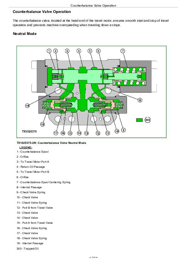
Counterbalance Valve Operation....1337
Transmission Operation....1341
Shift Interlock Operation....1347
Transmission Disconnect Operation....1348
Transmission Control Valve....1350
Park Brake Operation....1355
Service Brake Circuit Operation....1357
Brake Accumulator Charging Valve Operation....1363
Axle Lock Circuit Operation....1366
Group 15: Diagnostic Information....1314
Diagnose Transmission Malfunctions....1314
Diagnose Brake Malfunctions....1314
Travel Hydraulic System Schematic....1704
Travel Hydraulic System Component Location....1715
Travel Hydraulic System Line Identification....1432
Service Brake System Schematic....1433
Service Brake System Component Location....1435
Service Brake System and Axle Lock System Line Identification....1437
Axle Lock System Schematic....1438
Axle Lock System Component Location....1439
Group 20: Tests and Adjustments....1314
Transmission Manual Disconnection Procedure....1443
Brake Bleeding Procedure....1445
Brake Warning Set Pressure (Decrease)....1447
Brake Warning Set Pressure (Increase)....1450
Rear Brake Pressure Test....1453
Front Brake Pressure Test....1456
Transmission Control Valve Pressure Test....1459
Brake Accumulator Pressure Test....1462
Measure Swing Bearing Wear....1465
Section 9025: Hydraulic System....1468
Group 05: Theory of Operation....1468
Hydraulic System Diagram and Operation....1473
Pilot System Diagram and Operation....1475
Steering System Diagram and Operation....1484
Blade and/or Outrigger System Diagram and Operation....1486
Hydraulic Assist Diagram and Operation....1488
Two Piece Boom Positioning Diagram and Operation....1491
Pilot Pump, Pressure Regulating Valve and Filter Operation....1494
Pilot Shutoff Solenoid Valve Operation....1496
Pilot Control Valve Operation....1532
Travel Pilot Control Valve Operation....1532
Pilot Operation of Control Valve Operation....1532
Pilot Signal Manifold Operation....1508
Pump 1, Pump 2 and Drive Gearbox Operation....1519
Pump 1 and Pump 2 Regulator Operation....1522
Engine Speed Sensing Control Circuit Operation....1530
Control Valve Operation....1532
Control Valve Check Valves Identification and Operation....1545
Main Relief and Power Digging Valve Circuit Operation....1549
Circuit Relief and Anticavitation Valve Operation....1554
Auxiliary Flow Combiner Valve Operation....1556
Travel Flow Combiner Valve Operation....1562
Boom Lower Meter-In Cut Valve Operation....1565
Boom Regenerative Valve Circuit Operation....1568
Arm Regenerative Valve Circuit Operation....1571
Bucket Regenerative Valve Circuit Operation....1575
Boom and Arm Reduced Leakage Valves Operation....1578
Arm 1 Flow Rate Control Valve Circuit Operation....1580
Arm 2 Flow Rate Control Valve Circuit Operation....1584
Bucket Flow Rate Control Valve Circuit Operation....1588
Boom Flow Rate Control Valve Circuit Operation....1592
Auxiliary Flow Rate Control Valve Circuit Operation....1596
Swing Reduction Gearbox Operation....1597
Swing Motor, Crossover Relief Valve, and Make-Up Check Valve Operation....1598
Swing Motor Dampener Valve....1602
Swing Motor Park Brake Release Circuit Operation....1612
Center Joint Operation....1613
Steering Valve Operation....1615
Blade and/or Outrigger Check Valve Operation....1621
Cylinder Holding Valve Operation....1623
Cylinder Operation....1627
Return Filter Operation....1629
Group 15: Diagnostic Information....1469
Diagnose Hydraulic System Malfunctions....1469
Diagnose Pilot Circuit Malfunctions....1469
Diagnose Dig Circuit Malfunctions....1469
Diagnose Swing Circuit Malfunctions....1469
Diagnose Steering Circuit Malfunctions....1469
Diagnose Blade and/or Outrigger Circuit Malfunctions....1469
Pump 1, Pump 2, and Pilot Pump Line Identification....1693
Control Valve Line Identification....1694
Swing Motor Line Identification....1698
Pilot Control Valve-to-Pilot Signal Manifold Component Location—Excavator Pattern....1699
Pilot Signal Manifold-to-Control Valve Line Connection....1700
Steering System Component Location....1701
Steering System Line Connection....1702
Hydraulic System Schematic....1704
Hydraulic System Component Location....1715
Hydraulic System Line Connections....1717
Group 25: Tests....1469
JT05800 Digital Thermometer Installation....1719
JT02156A Digital Pressure/Temperature Analyzer Installation....1720
Hydraulic Oil Cleanup Procedure Using Portable Filter Caddy....1721
Hydraulic Oil Warm-Up Procedure....1722
Pilot Pressure Regulating Valve Test and Adjustment....1725
Control Valve Spool Actuating Pilot Pressure Test....1729
Arm Regenerative Solenoid Valve Test and Adjustment....1733
Power Digging Solenoid Valve Test and Adjustment....1738
Torque Control Solenoid Valve Test and Adjustment....1743
Axle Lock Solenoid Valve Test and Adjustment....1747
Work Brake Solenoid Valve Test and Adjustment....1752
Pump Control Pilot Pressure Signal Test....1757
Main Relief and Power Digging Valve Test and Adjustment....1760
Circuit Relief Valve Test and Adjustment....1766
Swing Motor Crossover Relief Valve Test and Adjustment....1775
Steering Relief Valve Pressure Test....1780
Two Piece Boom Positioning and Hydraulic Assist Relief Valve Test and Adjustment....1783
Pump Flow Test....1788
Swing Motor Leakage Test....1797
Steering System Leakage Test....1800
Steering Cylinder Leakage Test....1802
Cylinder Drift Test—Boom, Arm, and Bucket....1804
Section 9031: Heating and Air Conditioning....1806
Group 05: Theory of Operation....1806
Air Conditioning System Cycle of Operation....1809
Group 15: Diagnostic Information....1806
Diagnose Air Conditioning System Malfunctions....1814
Diagnose Heating System Malfunctions....1817
Heater and Air Conditioner Diagnostic Trouble Code Check....1819
Heater and Air Conditioner Component Location....1825
Group 25: Tests....1806
Refrigerant Cautions and Proper Handling....1827
Heater and Air Conditioner Operational Checks....1828
R134a Air Conditioning System Test....1832
Air Conditioner Compressor Clutch Test....1835
Refrigerant Leak Test....1836
Refrigerant Hoses and Tubing Inspection....1837
Air Conditioner Compressor Belt Check and Adjustment....1838
Operating Pressure Diagnostic Chart....1839
Section 9050: Reference Material....1841
Group 05: Terminology Cross Reference Chart....1844
Terminology Cross Reference Chart....1844
Section 9900: Dealer Fabricated Tools....1846
Group 99: Dealer Fabricated Tools....1846
DFT1218 Split Flange Hose Cap....1848
John Deere 220DW Wheeled Excavator Service Manual (Operation & Test - TM10544)
![]()