
Nissan 300ZX/350Z/370Z (Model Z31/Z32/Z33/Z34 Series) Service & Repair Manuals
Complete workshop repair service manual with electrical wiring diagrams for Nissan 300ZX/350Z/370Z (Z31-Z32-Z33-Z34). It's the same service manual used by dealers that guaranteed to be fully functional and intact without any missing page.
Nissan 300ZX/350Z/370Z (Z31-Z32-Z33-Z34) service & repair manual (including maintenance, overhaul, disassembling & assembling, adjustment, tune-up, operation, inspecting, diagnostic & troubleshooting…) is divided into different sections. Each section covers a specific component or system with detailed illustrations. A table of contents is placed at the beginning of each section. Pages are easily found by category, and each page is expandable for great detail. The printer-ready PDF documents work like a charm on all kinds of devices.
370Z, 370Z Nismo, 370Z Sport, 370Z Touring, 370Z Touring Sport
EXCERPT:
3.0L V6 VINS [R,C] 1995-96 Engines Nissan - 3.0L V6 - DOHC
Removal
1. Release fuel system pressure. See FUEL PRESSURE RELEASE. Remove cylinder head. See
CYLINDER HEAD. Remove camshaft sprockets and timing belt rear cover from cylinder head.
2. Remove Valve Timing Control (VTC) solenoid valves from rear of intake camshafts. Measure and record camshaft end play. Loosen camshaft bearing cap bolts in 2-3 steps, beginning with outer bolts and working inward.
3. Remove camshaft bearing caps. Remove camshaft, seals and hydraulic lifters. Mark hydraulic lifters for installation reference.
Inspection
Check camshaft journals and lobes for scratches, seizure and wear. Measure camshaft journal diameter, camshaft bearing bore diameter, camshaft runout, sprocket runout and lobe height. Determine oil clearance. Replace camshaft if measurements are not within specification. See CAMSHAFT under ENGINE SPECIFICATIONS.
Installation
1. Install hydraulic lifters. Install camshafts with knockpins at top of camshaft, centered between camshaft bearing cap bolt holes. Exhaust camshaft for left cylinder head is identified by splines on end of camshaft (for crank angle sensor).
2. Apply a thin coat of liquid gasket to cylinder head groove where valve timing control solenoid will be installed. Install valve timing control solenoid. Apply liquid gasket to front mating edge of front camshaft bearing caps. DO NOT allow liquid gasket to contact camshaft bearing surfaces.
3. Install camshaft bearing caps. Tighten cap bolts in 2-3 steps to specification, beginning at center cap and working outward. See TORQUE SPECIFICATIONS. Apply oil to NEW camshaft oil seal lip. Install NEW seal. To complete installation, reverse removal procedure.
REAR CRANKSHAFT OIL SEAL
Removal & Installation
Remove transmission. Remove flexplate/flywheel. Pry seal out of retainer. Lubricate NEW seal. Drive seal into retainer. To complete installation, reverse removal procedure.
THERMOSTAT Removal & Installation
1. Drain coolant from drain cocks on both sides of cylinder block and radiator. Remove the following parts:
…
SECTION HAC
HEATER & AIR CONDITIONING CONTROL SYSTEM
A/C AUTO AMP. (A/C AUTO AMPLIFIER)
Description
• The A/C auto amp. (1) has a built-in microcomputer which processes
information sent from various sensors needed for air conditioning system operation.
• The air mix door motor, mode door motor, intake door motor, blower motor and the compressor are then controlled.
• When the various switches and dials are operated, data is input to the A/C auto amp. from the A/C control via communication line.
• Self-diagnosis functions are also built into A/C auto amp. to provide quick check of malfunctions in the auto air conditioning system.
Component Function Check INFOID:0000000011737973
1.CHECK OPERATION
...
NVIS (NISSAN VEHICLE IMMOBILIZER SYSTEM-NATS)
System Description
NVIS (Nissan Vehicle Immobilizer System-NATS) has the following immobilizer functions:
• Since only NVIS (NATS) ignition keys, whose ID Nos. have been registered into the ECM and BCM, allow the engine to run, a vehicle operation without a key registered in NVIS (NATS) is prevented by NVIS (NATS).
That is to say, NVIS (NATS) will immobilize the engine if someone tries to start it without the registered key of NVIS (NATS).
• All of the originally supplied ignition key IDs (except for card plate key) have been registered in NVIS (NATS).
If requested by the vehicle owner, a maximum of five key IDs can be registered into the NVIS (NATS) components.
• The security indicator blinks when the ignition switch is in “OFF” or “ACC” position. Therefore, NVIS (NATS) warns outsiders that the vehicle is equipped with the anti-theft system.
• When NVIS (NATS) detects trouble, the security indicator lamp lights up while ignition key is in the “ON” position.
• NVIS (NATS) trouble diagnoses, system initialization and additional registration of other NVIS (NATS) ignition key IDs must be carried out using CONSULT-III hardware and CONSULT-III NVIS (NATS) software.
When NVIS (NATS) initialization has been completed, the ID of the inserted ignition key is automatically registered in NVIS (NATS). Then, if necessary, additional registration of other NVIS (NATS) ignition key IDs can be carried out.
Regarding the procedures of NVIS (NATS) initialization and NVIS (NATS) ignition key ID registration, refer to
CONSULT-III Operation Manual NATS-IVIS/NVIS.
• When servicing a malfunction of the NVIS (NATS) (indicated by lighting up of Security Indicator Lamp) or registering another NVIS (NATS) ignition key ID No., it may be necessary to re-register original key identification. Therefore, be sure to receive ALL KEYS from vehicle owner.
System Composition
The immobilizer function of the NVIS (NATS) consists of the following:
• NATS ignition key
• NATS antenna amp. located in the ignition key cylinder
• BCM
• Engine control module (ECM)
• Security indicator
NOTE: The communication between ECM and BCM uses the CAN communication system.
...
84circuit...3
84circuit2...4
AT...5
DESCRIPTION OF E4N71B...6
GENERAL SERVICE NOTICE...8
ON-VEHICLE SERVICE...14
REMOVAL AND INSTALLATION t...22
MAJOR OVERHAUL...24
DISASSEMBLY...26
REPAIR FOR COMPONENT PARTS...32
ASSEMBLY...53
TROUBLE-SHOOTING AND DIAGNOSES...67
SERVICE DATA AND SPECIFICATIONS (S D.S...99
SPECIAL SERVICE TOOLS...103
BF...104
BR...181
Body...202
CL...279
EFEC...291
EL...370
HOW TO READ DIAGRAMS...371
STANDARDIZED RELAY...372
POWER SUPPLY ROUTING...373
BATTERY...375
STARTING SYSTEM...378
STARTING SYSTEM -Starter -...379
CHARGING SYSTEM...384
CHARGING SYSTEM - Alternator...386
COMB IN AT1 ON SWITCH...392
INSTRUMENT SWITCH...394
HEADLAMP...395
EXTERIOR LAMP...403
INTERIOR LAMP...407
METER AND GAUGES - Digital Type Combination Meter...410
METER AND GAUGES - Digital Type Combination Gauge...426
METER AND GAUGES - Needle Type Combination Meter...434
METER AND GAUGES - Needle Type Combination Gauge...437
WARNING LAMPS AND CHIME...440
VOICE WARNING SYSTEM...445
TIME CONTROL SYSTEM...450
WIPER AND WASHER...458
HORN CIGARETTE LIGHTER CLOCK...461
REAR WINDOW DEFOGGER...462
AUDIO AND POWER ANTENNA...464
AUTOMATIC SPEED CONTROL DEVICE (AS C D )...466
LOCATION OF ELECTRICAL UNITS...473
EM...486
Engine...530
Engine Mechanical...530
Engine Components (Outer Parts)...531
Compression Pressure...533
Timing Belt...534
Removal...535
Inspection...536
Installation...538
Cylinder Head...542
Removal...543
Disassembly...544
Inspection...545
Assembly...551
Installation...551
Distributor Installation...554
Oil Pan...555
Removal...555
Oil Seal Replacement...556
Camshaft Oil Seal...556
Valve Oil Seal...556
Engine Removal...557
Engine Overhaul...558
Cylinder Block, Crankshaft & Piston...558
Disassembly...559
Inspection...559
Assembly...564
Service Data and Specifications...567
General Specifications...567
Inspection and Adjustment...567
Tightening Torque...574
Special Service Tools...575
FA...577
FE...601
GI...607
PRECAUTIONS...608
HOW TO USE THIS MANUAL...611
IDENTIFICATION INFORMATION...614
RECOMMENDED FUEL AND LUBRICANTS...620
LIFTING TOWING AND TIE-DOWN POINTS...621
HA...624
GENERAL DESCR I PTlON...625
AIR FLOW AND COMPONENT LAYOUT...626
LOCATION OF VACUUM COMPONENTS...628
DOOR CONTROL...629
HEATER ELECTRICAL CIRCUIT...630
DESCRIPTION-Air Conditioner (Manual)...632
DISCHARGING EVACUATING CHARGING AND CHECKING...635
A/C PERFORMANCE TEST...641
PRECAUTIONS FOR REFRIGERANT CONNECTION...643
PIPING COMPRESSOR MOUNTING AND F.1 C D...644
COMPRESSOR OIL-ForMJS170...646
COMPRESSOR-Model MJS170...648
A/C ELECTRICAL CIRCUIT (Manual)...653
A/C ELECTRICAL COMPONENTS (Manual)...655
LOCATION OF A/C ELECTRICAL COMPONENTS...657
SERVICE DATA AND SPECIFICATIONS (S D S )...658
SPECIAL SERVICE TOOLS...661
LC...662
MA...680
MT...718
PD...752
PROPELLER SHAFT...753
INSPECTION...753
REMOVAL...753
I NSTALLATI ON...753
CHECKING AND CORRECTING UNBALANCED PROPELLER SHAFT...753
DIFFERENTIAL CARRIER (Type R200)...754
REMOVAL...755
PRE-DISASSEMBLY INSPECTION...755
DISASSEMBLY...755
DIFFERENTIAL CASE...756
INSPECTION...756
ASSEMBLY AND ADJUSTMENT...757
PRECAUTIONS IN REASSEMBLY...757
ASSEMBLY OF DIFFERENTIAL GEAR CASE...757
ADJUSTMENT OF DRIVE PINION PRELOAD...757
ADJUSTMENT OF DRIVE PINION HEIGHT...758
ADJUSTMENT OF SIDE BEARING WASHERS...759
INSTALLATION...761
REPLACEMENT OF OIL SEALS...761
FRONT OIL SEAL...761
SIDE OIL SEAL...761
SERVICE DATA AND SPECIFICATIONS (S D S)...762
SPECIAL SERVICE TOOLS...764
RA...767
REAR AXLE AND REAR SUSPENSION...768
REAR AXLE -Axle Shaft...770
DRIVE SHAFT...772
DRIVE SHAFT - 'Tripod-Tripod' Type...773
DRIVE SHAFT - 'Double Offset-6irfield'Type...778
REAR SUSPENSION...779
REAR SUSPENSION -Adlustable Shock Absorber...784
SERVICE DATA AND SPECIFICATIONS (S D.S )...786
ST...789
fwd...809
'85...811
Automatic Transmission...812
Automatic Transmission...812
Description...813
General Service Notice...815
Repair Notes...815
Control Valve...815
Lockup Control Valve and O.D. Cancel Valve...816
Oil Channel...817
Mechanical Operation...818
Hydraulic Control Circuits...819
On-Vehicle Service...820
Control Valve...820
Extension Oil Seal...821
Parking Component...821
Governor Valve Assembly...822
Inhibitor Switch Adjustment...822
Manual Linkage Adjustment...823
Vacuum Diaphragm Rod Adjustment...824
Downshift Solenoid...824
Kickdown Switch Adjustment...825
Overdrive and Lockup Control...826
Removal and Installation...827
Major Overhaul...829
Disassembly...831
Repair for Component Parts...837
Oil Pump...837
Drum Support...839
Control Valve Body...843
Oil Distributor...847
Direct Clutch...848
Front Clutch...851
Rear Clutch (Forward)...854
Low & Reverse Brake...855
Brake Band and Band Servo...856
Governor...857
Accumulator...857
Planetary Carrier...858
Connecting Drum Assembly...858
O.D. One-Way Clutch...859
Assembly...860
Trouble-shooting and Diagnoses...874
Preliminary Checks...874
Road Testing...874
Road Test Symptom Chart...879
Trouble-Shooting Chart...880
Electrical System/Schematic...883
Electrical System/Wiring Diagram...884
Inspection of A/T Control Unit...885
Inspection of Lockup Control...887
Inspection of O.D. Control...889
Inspection of Parts related to ASCD...890
Inspection of Kickdown Control...892
Self Diagnostics...893
Pressure Testing...895
Stall Testing...897
Service Data and Specifications...899
Special Service Tools...903
Body...904
Body...904
General Servicing...905
Body End and Door...909
Front End...909
Rear End...911
Back Door and Fuel Filler Lid Opener...912
Front Door...913
Power Window Wiring...914
Power Door Lock Wiring...915
Seat...916
Manual Driver Seat...916
Semi-Power Driver Seat...917
Full Power Driver Seat...921
Front Assist Seat...925
Rear Seat...926
Seat Belt...927
Instrument...928
Interior and Exterior...929
Inside Trim...929
Exterior...931
Windshield and Windows...935
Windshield...935
Back Door Window...937
Side Window...938
Repairing Leaks...939
T-Bar Roof...940
Mirror...941
Rear Air Spoiler and High-mounted Stop Lamp...942
Rear Combination Lamp...943
Body Alignment...944
Engine Compartment...944
Underbody...947
Brakes...951
Brake System...951
Brake Hydraulic Line...952
Precautions...952
Bleeding Procedure...952
Removal and Installation...953
Inspection...953
Brake Pedal...954
Inspection...954
Adjustment...955
Master Cylinder...956
Brake Booster...957
Operating Check...957
Airtight Check...957
Removal and Installation...957
Inspection...958
Front Disc Brake - Caliper...959
Pad Replacement...959
Removal and Installation...960
Disassembly...960
Inspection...960
Assembly...960
Front Disc Brake - Rotor...961
Inspection...961
Rear Disc Brake - Caliper...962
Pad Replacement...963
Removal and Installation...963
Disassembly...964
Inspection...965
Assembly...965
Rear Disc Brake - Rotor...966
Inspection...966
Parking Brake...967
Removal...967
Inspection...967
Adjustment...968
Service Data and Specifications...969
General Specifications...969
Inspection and Adjustment...969
Tightening Torque...970
Special Service Tool...971
Circuit...973
Clutch...977
Clutch...977
Hydraulic Clutch Control...978
Precautions...978
Bleeding Procedure...979
Adjusting Clutch Pedal...979
Clutch Master Cylinder...980
Operating Cylinder...981
Clutch Damper...981
Clutch Control - Release Bearing...982
Clutch Unit...983
Service Data and Specifications...986
Special Service Tools...988
Electrical...989
Electrical System...989
How to read Diagrams...990
Standardized Relay...993
Power Supply Routing...994
Battery...997
How To Handle Battery...997
Specific Gravity Check...999
Battery Test and Charging Chart...1000
Starting System...1005
Starter...1006
Construction...1006
Magnetic Switch Check...1007
Pinion/Clutch Check...1007
Brush Check...1008
Field Coil Check...1008
Armature Check...1009
Assembly...1010
Service Data and Specifications...1010
Charging System...1011
Wiring Diagram - Turbo...1011
Wiring Diagram - Non-Turbo...1012
Trouble Shooting...1013
Alternator...1014
Construction (Mitsubishi)...1014
Construction (Hitachi)...1014
Removal...1015
Disassembly...1015
Rotor Slip Ring Check...1015
Brush Check...1016
Stator Check...1016
Diode Check...1017
Assembly...1018
Service Data and Specifications...1019
Combination Switch...1020
Check...1020
Replacement...1021
Instrument Switch...1022
Headlamp...1023
Schematic...1023
Wiring Diagram...1024
Operation...1028
Description...1029
Trouble Shooting...1037
Removal...1038
Installation...1039
Adjustment...1039
Headlamp Motor Check...1040
Aiming Adjustment...1040
Exterior Lamp...1041
Clearance, License, Tail, & Stop lamps Wiring Diagram...1041
Auxiliary Driving Lamp Wiring Diagram...1043
Back-up lamp Wiring Diagram...1043
Turn Signal & Hazard Warning lamps Wiring Diagram...1044
Stop and Tail lamp Sensor Check...1045
Bulb Specifications...1045
Interior Lamp...1046
Needle Type Combo Meter (SF & GL)...1046
Digital Combo Meter (GLL)...1047
Interior, Luggage and Step lamps...1048
Illuminated Entry/Door Key...1051
Meter and Gauges...1053
Digital Combo Meter...1053
Schematic...1055
Wiring Diagram...1056
Display Check...1058
Preparation for Trouble Shooting...1059
Trouble Shooting...1059
Power Unit Check...1065
Boost Sensor Check...1065
Speed Sensor Signal Check...1066
Fuel Tank Gauge Check...1068
Water Temp Sensor Check...1068
Oil Pressure Sensor Check...1068
Digital Combo Gauge...1069
Schematic...1069
Wiring Diagram...1070
Trouble Shooting...1071
Direction Sensor Amplifier Check...1075
Compass Input Check...1075
Direction Sensor Check...1076
Direction Sensor Installation...1076
Needle Type Combo Meter...1077
Tacho, Fuel & Water Temp Gauges...1078
Fuel Tank Gauge Check...1079
Speed Sensor Signal Check...1079
Speedometer Cable Removal...1079
Needle Type Combo Gauge...1080
Oil Temp Sensor Check...1081
Boost Gauge Trimmer Adjustment...1081
Oil Temp, Oil Pressure, Boost & Volt Gauges...1082
Warning Lamp and Chimes...1083
Schematic...1083
Warning lamp Wiring Diagram - Digital Combo Meter...1084
Turbo...1084
Non-Turbo...1085
Warning lamp Wiring Diagram - Needle Type Combo Meter...1086
Turbo...1086
Non-Turbo...1087
SF Model...1088
Warning Chime Wiring Diagram...1089
SF Model...1089
GL & GLL Models...1090
Diode Check...1091
Warning Chime Check...1091
Voice Warning System...1092
Schematic...1092
Wiring Diagram...1093
Needle Type Combo Meter...1093
Digital Type Combo Meter...1094
Operational Check...1095
Trouble Shooting...1096
Time Control System...1098
Schematic...1098
Wiring Diagram...1099
SF Model...1099
GL & GLL Models...1100
Preparation for Trouble Shooting...1101
Power Supply Circuit Check...1101
Trouble Shooting...1101
Wiper and Washer...1107
Wiring Diagram...1107
Installation...1107
Washer Nozzle Adjustment...1108
Rear Wiper/Washer Wiring Diagram...1109
Headlamp Washer Wiring Diagram...1110
Horn, Cigarette Lighter, Clock...1111
Rear Window Defogger...1112
Wiring Diagram...1112
Filament Check...1113
Filament Repair...1113
Audio and Power Antenna...1115
Wiring Diagram...1115
SF & GL Models...1115
GLL Model...1116
Power Antenna Motor Check...1117
Radio Fuse Check...1117
Automatic Speed Control Device...1118
Schematic...1118
Wiring Diagram...1119
Needle Type Combo Meter...1119
Digital Combo Meter...1120
Preparation for Trouble Shooting...1121
Trouble Shooting...1121
ASCD Actuator Check...1124
ASCD Wire Adjustment...1125
Steering Wheel Switch System...1126
Description...1126
Removal and Installation...1130
Schematic...1133
Wiring Diagram...1134
Trouble Shooting...1136
Receiver Check...1142
Head Amplifier Check...1143
Slip Ring Check...1143
Transmitter Check...1144
Steering Wheel Switch Check...1145
ASCD Control Unit Check...1146
Radio Check...1146
Theft Warning System...1148
Location of Electrical Units...1148
Operation of Switches and Sensors...1148
Schematic...1150
Wiring Diagram...1152
Trouble Shooting...1154
Engine Fuel & Emission...1193
Engine Fuel & Emission Control System...1193
Precautions...1194
Component Parts Location...1195
ECCS Diagram...1196
Non-Turbo...1196
Turbo...1197
ECCS Chart...1198
Non-Turbo...1198
Turbo...1199
ECCS Wiring Diagram...1200
Fuel Flow System Description...1202
Air Flow System Description...1203
Vacuum Control Valve...1204
Turbocharger...1204
Emergency Relief Valve...1204
ECCS Component Description...1205
Control Unit...1205
Crank Angle Sensor...1205
Air Flow Meter...1206
Head Temp Sensor...1207
Exhaust Gas Sensor...1207
Throttle Valve Switch...1208
Vehicle Speed Sensor...1208
Fuel Temp Sensor...1209
Detonation Sensor...1209
Fuel Injector...1209
Power Transistor...1210
Ignition Coil...1210
Idle-Up Solenoid Valve...1210
EGR Control Valve...1211
EGR Control Solenoid Valve...1211
Fuel Pump...1211
Air Regulator...1212
Air Injection Valve...1212
AIV Control Solenoid Valve...1212
Pressure Regulator Control Solenoid Valve...1213
ECCS System Description...1214
Fuel Injection Control...1214
Ignition Timing Control...1217
Idle-Up Control (Non-Turbo)...1218
Idle Speed Control (Turbo)...1219
Exhaust Gas Recirculation Control...1220
Fuel Pump Control...1221
Air Injection Valve Control...1222
Pressure Regulator Control...1223
Air Regulator Control...1224
Exhaust Gas Sensor Heater Control...1224
Air Flow Meter Self Cleaning Control...1225
Fail Safe System...1226
Diagnostic Procedure...1227
Caution...1227
Tips on Diagnoses...1227
Driveability...1228
Improper Idling and Stall...1230
Engine Startability...1231
Idle Speed and Ignition Timing Inspection...1232
Idle Mixture Ratio Inspection...1235
Self Diagnoses...1236
Electronic Control System Inspection...1242
Crank Angle Sensor...1242
Air Flow Meter...1245
Cylinder Head Temperature Sensor...1248
Vehicle Speed Sensor...1250
Ignition Signal...1251
Fuel Pump...1254
Throttle Valve Switch...1255
Neutral Switch...1257
Load Signal...1259
Air Conditioner Signal...1260
Start Signal...1261
Detonation Sensor...1262
Fuel Temperature Sensor...1263
Injector...1265
Battery Voltage and Ground Test...1267
Air Regulator...1269
EGR Control System...1271
Exhaust Gas Sensor...1274
Auxiliary Air Control Valve or Idle-Up Solenoid Valve...1276
Self Cleaning Hot Wire...1277
Pressure Regulator Control Solenoid Valve...1278
Air Injection Valve Control System...1281
Mixture Ratio Feedback System Inspection...1284
Fuel System Inspection...1287
Releasing Fuel Pressure...1287
Fuel Pressure Check...1287
Injector Removal and Installation...1289
Turbocharger...1290
Injector Cooling Fan...1293
Crankcase Emission Control System...1297
Exhaust Emission Control System...1298
Evaporative Emission Control System...1299
Service Data and Specifications...1301
Engine Fuel & Exhaust...1302
Engine Control, Fuel & Exhaust Systems...1302
Engine Control System...1303
Fuel System...1304
Removal of Fuel Tank...1305
Removal of Fuel Gauge Unit...1305
Removal of Electric Fuel Pump...1305
Exhaust System...1307
Cautions...1306
Engine...1308
Engine Mechanical...1308
Engine Components (Outer Parts)...1309
Compression Pressure...1311
Timing Belt...1312
Removal...1313
Inspection...1314
Installation...1316
Cylinder Head...1320
Removal...1321
Disassembly...1322
Inspection...1323
Assembly...1329
Installation...1329
Distributor Installation...1332
Oil Pan...1333
Removal...1333
Oil Seal Replacement...1334
Camshaft Oil Seal...1334
Valve Oil Seal...1334
Engine Removal...1335
Engine Overhaul...1336
Cylinder Block, Crankshaft & Piston...1336
Disassembly...1337
Inspection...1337
Assembly...1342
Service Data and Specifications...1345
General Specifications...1345
Inspection and Adjustment...1345
Tightening Torque...1352
Special Service Tools...1353
Front Axle & Front Suspension...1355
Front Axle & Front Suspension...1355
Front Axle and Front Suspension...1356
Front Axle - Wheel Hub...1357
Removal...1358
Inspection...1358
Installation...1358
Preload Adjustment...1359
Front Suspension...1360
Spring and Strut Assembly...1361
Removal and Installation...1361
Disassembly...1361
Inspection...1362
Assembly...1363
Tension Rod and Stabilizer Bar...1365
Transverse Link...1366
Removal and Installation...1366
Inspection...1367
Suspension Crossmember...1368
Adjustable Shock Absorber...1369
Removal and Installation...1369
Disassembly...1370
Inspection...1370
Assembly...1370
Harness Description...1372
Electrical Circuit...1372
Trouble Diagnoses...1374
Service Data and Specifications...1377
General Specifications...1377
Inspection and Adjustment...1378
Tightening Torque...1378
Special Service Tools...1379
General Info...1380
General Information...1380
Precautions...1381
General...1381
For Catalyst...1382
For EFI or ECCS Engine...1383
For Turbocharger...1383
How to use this Manual...1384
Identification Information...1387
Model Variation...1387
Identification Number...1389
Dimensions...1391
Recommended Fuel and Lubricants...1392
Lifting and Towing Points...1394
Pantograph Jack...1394
Garage Jack and Safety Stand...1394
2 point Lift...1395
Towing...1396
Tightening Torque of Standard Bolt...1397
Heater & AC...1398
Heater & Air Conditioner...1398
General Description...1399
Air Flow and Component Layout (Manual)...1400
Air Flow...1400
Component Layout...1401
Location of Vacuum Components...1402
Control...1403
Heater Electrical Circuit...1404
Schematic...1404
Wiring Diagram...1405
Description - A/C (Manual)...1406
Refrigeration Cycle...1406
Refrigerant Leak Warning System...1407
Discharging, Evacuating, Charging and Checking...1409
Precautions...1409
Discharging...1409
Evacuating the System...1410
Charging...1410
Checking Refrigerant Level...1413
Checking Refrigerant Leaks...1414
A/C Performance Test (Manual)...1415
Precautions for Refrigerant Connection...1417
Piping, Compressor, Mounting and FICD...1418
Refrigerant Lines...1418
Compressor Mounting...1418
Idle Speed Adjusting and Checking...1419
Compressor Oil (MJS170)...1420
Compressor (MJS170)...1422
Leak Test...1423
Clutch Replacement...1423
Shaft Seal Replacement...1424
Valve Replacement...1425
A/C Electrical Circuit (Manual)...1427
Schematic...1427
Wiring Diagram...1428
A/C Electrical Components (Manual)...1429
Location of A/C Electrical Components (Manual)...1431
Trouble Diagnoses (Manual)...1432
Circuit for Trouble Diagnoses...1433
Preliminary Check...1434
1...1434
2...1435
3...1436
4...1437
Trouble Diagnoses from Abnormal Conditions...1438
A...1438
B...1439
C...1440
D...1441
E...1443
F...1445
G...1447
H...1449
I...1450
J...1452
K...1455
L...1455
M...1456
N...1458
P...1458
Q...1459
R...1462
S...1463
Description - A/C (Auto)...1464
Features...1464
Refrigerant Cycle...1465
Function of Switches on Control Unit...1466
Basic Control Function and Control Switches...1467
Display of the Air Flow Indicator...1468
Display of Temperature Setting...1468
Control System...1469
System Operation...1470
Air Mix Door Control...1470
Intake Door Control...1475
Outlet Door Control...1476
Air Flow Volume Control...1478
Control at Starting...1480
Compressor, Water Cock Control & compensation for Ambient Temperature...1481
Function of Set TEMP Adjuster...1482
Function of Self Diagnoses of Trouble...1483
Air Flow and Component Layout (Auto)...1484
Air Flow...1484
Component Layout...1485
Location of Vacuum Components (Auto)...1486
A/C Performance Test (Auto)...1487
A/C Performance Test / Piping (Auto)...1488
A/C Electrical Circuit (Auto)...1489
Schematic...1489
Wiring Diagram...1491
...
EL...13397
TABLE OF CONTENTS...13397
PRECAUTIONS...13400
Supplemental Restraint System (SRS) 'AIR BAG'...13400
Special Service Tools...13400
HARNESS CONNECTOR...13401
Description...13401
STANDARDIZED RELAY...13402
Description...13402
POWER SUPPLY ROUTING...13406
Schematic...13406
Wiring Diagram - POWER -...13408
Fuse...13417
Fusible Link...13417
Circuit Breaker Inspection...13417
GROUND DISTRIBUTION...13418
BATTERY...13422
How to Handle Battery...13422
Service Data and Specifications (SDS)...13424
STARTING SYSTEM...13425
System Description...13425
Wiring Diagram - START -...13426
Construction...13428
Removal and Installation...13428
Service Data and Specifications (SDS)...13429
CHARGING SYSTEM...13430
System Description...13430
Wiring Diagram - CHARGE -...13431
Construction...13432
Removal and Installation...13433
Service Data and Specifications...13434
COMBINATION SWITCH...13435
Combination Switch/Check...13435
Combination Switch/Replacement...13436
INSTRUMENT SWITCH...13438
Check...13438
HEADLAMP...13440
System Description (For U.S.A.)...13440
Schematic...13442
Wiring Diagram - H/LAMP -...13443
Trouble Diagnoses...13446
HEADLAMP - Daytime Light System...13447
System Description (For Canada)...13448
Operation (Daytime light system equipped model)...13449
Schematic...13449
Wiring Diagram - DTRL -...13449
Trouble Diagnoses (Daytime Light)...13454
Aiming Adjustment...13456
Bulb Replacement...13457
EXTERIOR LAMP...13458
Clearance, License and Tail Lamps/Schematic...13458
Clearance, License, Tail and Stop Lamps/Wiring Diagram - TAIL -...13459
Stop and Tail Lamp Sensor Check...13462
Back-up Lamp/Wiring Diagram - BACK/L -...13463
Front Fog lamp/System Description...13464
Front Fog Lamp/Schematic...13465
Front Fog Lamp/Wiring Diagram - F/FOG -...13466
Turn Signal and Hazard Warning Lamps/System Description...13469
Turn Signal and Hazard Warning Lamps/Schematic...13471
Turn Signal and Hazard Warning Lamps/Wiring Diagram - TURN -...13472
Turn Signal and Hazard Warning lamps/Trouble Diagnoses...13475
Combination Flasher Unit Check...13475
Bulb Specifications...13476
INTERIOR LAMP...13477
Illumination/System Description...13477
Illumination/Schematic...13478
Illumination/Wiring Diagram - ILL -...13479
Interior, Spot, Foot, Luggage Room and Trunk Room Lamps/System Description...13482
Bulb Specifications...13483
Interior, Spot, Foot, Luggage Room and Trunk Room Lamps/Wiring Diagram - INT/L -...13484
METER AND GAUGES...13488
System Description...13488
Combination Meter...13489
Speedometer, Tachometer, Temp., Oil, Fuel and Boost Gauges/Wiring Diagram - METER -...13490
Inspection/Fuel Gauge and Water Temperature Gauge...13492
Fuel Tank Gauge Unit Check...13493
Thermal Transmitter Check...13493
Oil Pressure Sending Unit Check...13493
Boost Sensor Check...13494
Vehicle Speed Sensor Signal Check...13494
WARNING LAMPS AND CHIME...13495
Warning Lamps/Schematic...13495
Warning Lamps/Wiring Diagram - WARN -...13496
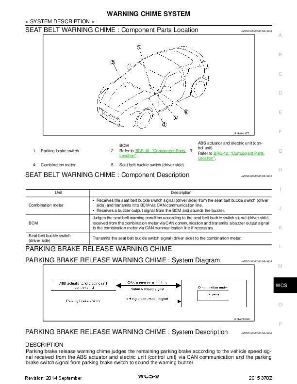
Warning Chime/System Description...13502
Warning Chime/Wiring Diagram - CHIME -...13504
Fuel Warning Lamp Sensor Check...13506
Diode Check...13506
Warning Chime Check...13506
TIME CONTROL SYSTEM...13507
System Description...13507
Schematic...13509
Wiring Diagram - TIME -...13510
Trouble Diagnoses...13517
WIPER AND WASHER...13527
Front Wiper and Washer/System Description...13527
Front Wiper and Washer/Schematic...13529
Front Wiper and Washer/Wiring Diagram - WIPER -...13530
Rear Wiper and Washer/System Description...13533
Rear Wiper and Washer/Wriing Dagram - WIP/R -...13534
Headlamp Washer/Wiring Diagram - HLC -...13535
Installation...13537
Washer Nozzle Adjustment...13538
Check Valve...13538
Wiper Amplifier Check...13538
POWER WINDOW...13539
System Description...13539
Schematic...13541
Wiring Diagram - WINDOW -...13542
Power Window Amp. Inspection...13545
POWER DOOR LOCK...13546
System Description...13546
Schematic...13547
Wiring Diagram - D/LOCK -...13548
Door Lock Timer Inspection...13552
Electrical Components Inspection...13553
POWER DOOR MIRROR...13554
Wiring Diagram - MIRROR -...13554
FUEL FILLER LID OPENER...13556
Wiring Diagram - F/LID - ...13556
TRUNK LID OPENER...13557
Wiring Diagram - T/LID -...13557
CONVERTIBLE ROOF...13559
Storage Lid Opener/System Description...13559
Storage Lid Opener/Schematic...13560
Storage Lid Opener/Wiring Diagram - ST/LID -...13561
Convertible Roof Opener/Wiring Diagram - C/ROOF -...13565
HORN, CIGARETTE LIGHTER AND CLOCK...13566
Wiring Diagram - HORN -...13566
REAR WINDOW DEFOGGER AND DOOR MIRROR DEFOGGER...13568
Wiring Diagram - DEF -...13568
Filament Check...13571
Filament Repair...13572
AUDIO AND POWER ANTENNA...13573
Audio/System Description...13573
Audio/Wiring Diagram - AUDIO -...13574
Schematic...13578
Power Antenna/System Description...13579
Power Antenna/Wiring Diagram - P/ANT -...13580
Trouble Diagnoses...13581
Location of Antenna...13583
Antenna Rod Replacement...13583
Radio Fuse Check...13584
Window Antenna Repair...13585
POWER SEAT...13586
Schematic...13586
Wiring Diagram - SEAT -...13587
MULTI-REMOTE CONTROL SYSTEM...13590
System Description...13590
Schematic...13593
Wiring Diagram - MULTI -...13594
Trouble Diagnoses Preliminary Inspection...13600
Trouble Diagnoses...13601
AUTOMATIC SPEED CONTROL DEVICE (ASCD)...13607
Component Parts and Harness Connector Location...13607
System Description...13608
Schematic...13610
Wiring Diagram - ASCD -...13611
Trouble Diagnoses...13617
THEFT WARNING SYSTEM...13636
Component Parts and Harness Connector Location...13636
Trouble Diagnoses...13637
Schematic...13638
Wiring Diagram - THEFT -...13640
Trouble Diagnoses...13649
LOCATION OF ELECTRICAL UNITS...13666
Engine Compartment...13666
Passenger Compartment...13667
Luggage Compartment...13668
HARNESS LAYOUT...13670
Outline...13670
Engine Room Harness...13671
Main Harness...13674
Air Bag Harness...13677
Engine Control Harness...13678
Body Harness...13680
Door Harness LH...13686
Door Harness RH...13686
Back Door Harness...13687
Alternator Harness...13687
EM...13688
TABLE OF CONTENTS...13688
PRECAUTIONS...13689
Supplemental Restraint System (SRS) 'AIR BAG'...13689
Parts Requiring Angular Tightening...13689
Liquid Gasket Application Procedure...13689
PREPARATION...13690
Special Service Tools...13690
Commercial Service Tools...13692
OUTER COMPONENT PARTS...13693
COMPRESSION PRESSURE...13696
Measurement of Compression Pressure...13696
OIL PAN...13697
Removal...13697
Installation...13698
TIMING BELT...13699
Removal...13700
Inspection...13701
Installation...13702
OIL SEAL REPLACEMENT...13706
THROTTLE BODIES...13708
Precaution...13708
Installation...13708
CYLINDER HEAD...13710
Removal...13711
Disassembly...13712
Inspection...13713
Assembly...13718
Installation...13719
TURBOCHARGERS...13722
Removal...13722
Inspection...13724
CHARGE AIR COOLERS...13727
Removal...13727
ENGINE REMOVAL...13728
M/T Model...13729
A/T Model...13731
CYLINDER BLOCK...13732
Disassembly...13733
Inspection...13733
Assembly...13740
SERVICE DATA AND SPECIFICATIONS (SDS)...13743
General Specifications...13743
Inspection and Adjustment...13744
FA...13751
TABLE OF CONTENTS...13751
PRECAUTIONS AND PREPARATION...13752
Precautions...13752
Special Service Tools...13752
Commercial Service Tools...13752
FRONT AXLE AND FRONT SUSPENSION...13754
ON-VEHICLE SERVICE...13755
Front Axle and Front Suspension Parts...13755
Front Wheel Bearing...13757
Front Wheel Alignment...13758
FRONT AXLE...13760
Wheel Hub and Steering Knuckle...13760
FRONT SUSPENSION...13764
Coil Spring and Shock Absorber...13765
Third Link and Upper Link...13766
Transverse Link and Lower Ball Joint...13768
Tension Rod and Stabilizer Bar...13769
ADJUSTABLE SHOCK ABSORBER...13770
Trouble Diagnoses...13771
SERVICE DATA AND SPECIFICATIONS (SDS)...13778
General Specifications...13778
Inspection and Adjustment...13779
FE...13780
TABLE OF CONTENTS...13780
ACCELERATOR CONTROL SYSTEM...13781
Adjusting Accelerator Wire...13781
FUEL SYSTEM...13782
EXHAUST SYSTEM...13784
FOLDOUT...13786
FUSE BLOCK JUNCTION BOX (J/B)...13786
Terminal Arrangement...13786
ELECTRICAL UNIT...13787
Terminal Arrangement...13787
FWD...13788
QUICK REFERENCE INDEX...13788
FOREWORD...13789
Quick Reference Chart...13790
GI...13791
TABLE OF CONTENTS...13791
PRECAUTIONS...13792
Precautions for Suplemental Restraint System (SRS) 'AIR BAG'...13792
General Precautions...13792
Precautions for Multiport Fuel Injection System or ECCS Engine...13794
Precautions for Three Way Catalyst...13794
Precautions for Turbocharger...13794
Engine Oils...13795
Precautions for Fuel...13796
Precautions for Air Conditioning...13796
HOW TO USE THIS MANUAL...13797
HOW TO READ WIRING DIAGRAMS...13799
Sample/Wiring Diagram - EXAMPL -...13799
Description...13801
Wiring Diagram Codes (Cell Codes)...13807
HOW TO PERFORM EFFICIEINT DIAGNOSIS FOR AN ELECTRICAL INCIDENT...13809
Work Flow...13809
Incident Simulation Test...13810
Circuit Inspection...13814
HOW TO FOLLOW FLOW CHART IN TROUBLE DIAGNOSES...13820
CONSULT CHECKING SYSTEM...13823
Function and System Application...13823
Lithium Battery Replacement...13823
Checking Equipment...13823
IDENTIFICATION INFORMATION...13824
Model Variation...13824
Identification Number...13826
Dimensions...13828
Wheels and Tires...13828
LIFTING POINTS AND TOW TRUCK TOWING...13829
Preparation...13829
Board-on Lift...13829
Garage Jack and Safety Stand...13830
2-pole Lift...13831
Tow Truck Towing...13831
TIGHTENING TORQUE OF STANDARD BOLTS...13833
SAE J1930 TERMINOLOGY LIST...13834
SAE J1930 Terminology List...13834
HA...13838
TABLE OF CONTENTS...13838
MANUAL AND AUTO...13839
PRECAUTIONS AND PREPARATION...13839
Supplemental Restraint System (SRS) 'AIR BAG'...13839
Introduction...13839
Identificiation...13839
Precautions for Working with HFC-134a (R-134a)...13841
General Refrigerant Precautions...13841
Precautions for Refrigerant Connection...13842
Precautions for Servicing Compressor...13843
Special Service Tools...13843
HFC-134a (R-134a)) Service Tools and Equipment...13844
Precautions for Service Equipment...13846
DESCRIPTION...13848
Refrigeration Cycle...13848
Component Layout...13849
Discharge Air Flow...13850
Acceleration Cut System...13851
Water Cock Control System...13851
MANUAL...13852
DESCRIPTION...13852
Control Operation...13852
TROUBLE DIAGNOSES...13853
Contents...13853
Wiring Diagram - A/C, M -...13874
SYSTEM DESCRIPTION...13901
Control Switches...13901
Specifications...13901
AUTO...13903
DESCRIPTION...13903
Features...13903
Control Operation...13904
TROUBLE DIAGNOSES...13905
Contents...13905
Wiring Diagram - A/C, A -...13932
SYSTEM DESCRIPTION...13966
Specifications...13966
System Operation...13969
MANUAL AND AUTO...13973
SERVICE PROCEDURES...13973
HFC-134a (R-134a) Service Procedure...13973
Maintenance of Lubricant Quantity in Compressor...13975
Refrigerant Lines...13977
Checking Refrigerant Leaks...13979
Compressor Mounting...13981
Belt Tension...13981
Fast Idle Control Device (FICD)...13981
Removal and Installation - Compressor...13982
Compressor - Model DKS-16H (ZEXEL make)...13983
SERVICE DATA AND SPECIFICATIONS (SDS)...13985
General Specifications...13985
Inspection and Adjustment...13985
IDX...13986
LC...13994
TABLE OF CONTENTS...13994
PRECAUTIONS...13995
Supplemental Restraint System (SRS) 'AIR BAG'...13995
Liquid Gasket Application Procedure...13995
PREPARATION...13996
Special Service Tools...13996
ENGINE LUBRICATION SYSTEM...13997
Lubrication Circuit...13997
Oil Pressure Check...13998
Oil Filter Bracket (Turbocharger model)...13998
Oil Pump...13998
Oil Cooler (Turbocharger model)...14000
ENGINE COOLING SYSTEM...14001
Cooling Circuit...14001
System Check...14001
Water Pump...14002
Thermostat...14003
Cooling Fan (Crankshaft driven)...14004
Cooling Fan (Motor driven)...14004
Radiator...14005
Overheating Cause Analysis...14010
SERVICE DATA AND SPECIFICATIONS (SDS)...14011
Engine Lubrication System...14011
Engine Cooling System...14011
MA...14012
TABLE OF CONTENTS...14012
PRECAUTIONS...14013
Supplemental Restraint System (SRS) 'AIR BAG'...14013
GENERAL MAINTENANCE...14014
PERIODIC MAINTENANCE...14016
Schedule 1...14017
Schedule 2...14018
RECOMMENDED FLUIDS AND LUBRICANTS...14019
Fluids and Lubricants...14019
SAE Viscosity Number...14019
Anti-freeze Coolant Mixture Ratio...14020
ENGINE MAINTENANCE...14021
Checking Drive Belts...14021
Changing Engine Coolant...14022
Checking Fuel Lines...14023
Changing Fuel Filter...14024
Changing Air Cleaner Filter...14024
Changing Engine Oil...14024
Changing Oil Filter...14025
Changing Spark Plugs...14026
Checking EVAP Vapor Purge Lines...14027
CHASSIS AND BODY MAINTENANCE...14028
Checking Exhaust System...14028
Checking Clutch Fluid Level and Leaks...14028
Checking M/T Oil...14028
Changing M/T Oil...14028
Checking A/T Fluid...14028
Changing A/T Fluid...14029
Checking Differential Gear Oil...14030
Changing Differential Gear Oil...14030
Balancing Wheels...14030
Tire Rotation (Non-Turbocharger model only)...14030
Checking Brake Fluid Level and Leaks...14031
Checking Disc Brake...14031
Checking Steering Gear and Linkage...14031
Checking Power Steering Fluid and Lines...14032
Checking SUPER HICAS Linkage (With SUPER HICAS system)...14032
Lubricating Locks, Hinges and Hood Latches...14033
Checking Seat Belts, Buckles, Retractors, Anchors and Adjusters...14033
SERVICE DATA AND SPECIFICATIONS (SDS)...14034
Engine Maintenance...14034
Chassis and Body Maintenance...14034
MT...14035
TABLE OF CONTENTS...14035
PREPARATION...14036
Special Service Tools...14036
Commercial Service Tool...14037
ON-VEHICLE SERVICE...14038
Replacing Rear Oil Seal...14038
Position Switch Check...14038
REMOVAL AND INSTALLATION...14039
Removal...14039
Installation...14039
MAJOR OVERHAUL...14040
Case Components...14040
Gear Components...14041
Shift Control Components...14043
DISASSEMBLY...14045
Case Components...14045
Shift Control Components...14046
Gear Components...14047
INSPECTION...14051
Shift Control Components...14051
Gear Components...14051
ASSEMBLY...14053
Gear Components...14053
Shift Control Components...14061
Case Components...14061
SERVICE DATA AND SPECIFICATIONS (SDS)...14064
General Specifications...14064
Inspection and Adjustment...14064
PD...14066
TABLE OF CONTENTS...14066
PREPARATION...14067
Special Service Tools...14067
Commercial Service Tools...14070
PROPELLER SHAFT...14071
On-vehicle Service...14072
Removal...14072
Installation...14073
Inspection...14073
Disassembly...14074
Assembly...14074
FINAL DRIVE...14075
ON-VEHICLE SERVICE/REMOVAL AND INSTALLATION...14075
Front Oil Seal Replacement (R200V)...14075
Side Oil Seal Replacement...14075
Removal...14076
Installation...14076
FINAL DRIVE...14077
Model R200V...14077
Model R230V...14078
DISASSEMBLY...14079
Pre-inspection...14079
Differential Carrier...14079
Differential Case...14081
INSPECTION...14082
Ring Gear and Drive Pinion...14082
Bearing...14082
Differential Case Assembly...14082
ADJUSTMENT (R200V)...14083
Side Bearing Preload...14083
Pinion Gear Height and Pinion Bearing Preload...14084
ADJUSTMENT (R230V)...14089
Side Bearing Preload...14089
Pinion Gear Height...14090
ADJUSTMENT...14093
Tooth Contact...14093
ASSEMBLY...14094
Differential Case...14094
Differential Carrier...14095
SERVICE DATA AND SPECIFICATIONS (SDS)...14100
Propeller Shaft...14100
Final Drive...14100
RA...14103
TABLE OF CONTENTS...14103
PRECAUTIONS AND PREPARATION...14104
Precautions...14104
Special Service Tools...14104
Commercial Service Tools...14105
REAR AXLE AND REAR SUSPENSION...14106
ON-VEHICLE SERVICE...14107
Rear Axle and Rear Suspension Parts...14107
Rear Wheel Bearing...14107
Rear Wheel Alignment...14107
Drive Shaft...14109
REAR AXLE AND REAR SUSPENSION ASSEMBLY...14110
Removal and Installation...14110
REAR AXLE...14111
Wheel Hub and Axle Housing...14111
Drive Shaft...14114
REAR SUSPENSION...14118
Coil Spring and Shock Absorber...14119
Multi-link and Lower Ball Joint...14120
Stabilizer Bar...14121
ADJUSTABLE SHOCK ABSORBER...14122
Removal and Installation...14122
Inspection...14122
Trouble Diagnosis...14122
SUPER HICAS...14123
Rear Wheel Alignment...14123
Rear Axle Housing Ball Joint...14124
SERVICE DATA AND SPECIFICATIONS (SDS)...14125
General Specifications...14125
Inspection and Adjustment...14126
RS...14127
TABLE OF CONTENTS...14127
PRECAUTION...14128
Supplemental Restraint System (SRS) 'AIR BAG'...14128
SEAT BELTS...14129
Front Seat Belt...14129
Rear Seat Belt (2+ 2 model)...14130
SUPPLEMENTAL RESTRAINT SYSTEM (SRS)...14131
Precautions for SRS 'Air Bag' Service...14131
Special Service Tools...14131
Description...14132
SRS Component Parts Location...14133
Maintenance Items...14134
Removal and Installation - Diagnosis Unit and Sensors...14135
Removal - Air Bag Module and Spiral Cable...14136
Removal - Front Passenger Air Bag Module...14137
Installation - Air Bag Module and Spiral Cable...14138
Installation - Front Passenger Air Bag Module...14139
Disposal or Air Bag Module...14140
TROUBLE DIAGNOSES - Supplemental Restraint System (SRs)...14144
Schematic...14144
Wiring Diagram...14145
Self-diagnosis...14149
Diagnostic Procedure 1...14155
Diagnostic Procedure 2...14156
Collision Diagnosis...14157
ST...14158
TABLE OF CONTENTS...14158
PRECAUTIONS AND PREPARATION...14159
Supplemental Restraint System (SRS) 'AIR BAG'...14159
Steering System...14159
Special Service Tools...14159
Commercial Service Tools...14161
CONSULT Program Card...14161
ON-VEHICLE SERVICE...14162
Checking Steering Wheel Play...14162
Checking Neutral Position on Steering Wheel...14162
Front Wheel Turning Angle...14162
Adjusting Rack Retainer...14163
Checking and Adjusting Drive Belts (For power steering)...14163
Checking Fluid Level...14163
Checking Fluid Leakage...14164
Bleeding Hydraulic System...14164
Checking Steering Wheel Turning Force (For power steering)...14164
Checking Hydraulic System...14165
STEERING WHEEL AND STEERING COLUMN...14166
Removal and Installation...14166
Disassembly and Assembly...14168
Inspection...14169
POWER STEERING GEAR AND LINKAGE (Model PR26AE)...14170
Removal and Installation...14170
Disassembly...14173
Inspection...14173
Assembly...14174
Adjustment...14179
POWER STEERING OIL PUMP...14181
Pre-disassembly Inspection...14181
Disassembly...14181
Inspection...14182
Assembly...14182
TWIN ORIFICE POWER STEERING SYSTEM...14184
Hydraulic Circuit...14184
Schematic...14184
Wiring Diagram...14185
Trouble Diagnoses...14188
SUPER HICAS SYSTEM...14197
HICAS Component Parts Location...14197
System Diagram...14197
On-vehicle Service...14198
Repair of Component Parts...14200
Trouble Diagnoses...14205
SERVICE DATA AND SPECIFICATIONS...14244
General Specifications...14244
Inspection and Adjustment...14244
...
SM3E-1Z33U0...3
acc...5
Table of Contents...5
ACCELERATOR CONTROL SYSTEM...6
Precautions for Battery Service...6
Removal and Installation...6
REMOVAL...6
INSTALLATION...6
INSPECTION AFTER INSTALLATION...7
SERVICE DATA AND SPECIFICATIONS (SDS)...8
Tightening Torque...8
acs...9
Table of Contents...9
AUTOMATIC SPEED CONTROL DEVICE (ASCD)...10
Description...10
at...11
Table of Contents...11
INDEX FOR DTC...15
Alphabetical Index...15
DTC No. Index...16
PRECAUTIONS...17
Precautions for Supplemental Restraint System (SRS) “AIR BAG” and “SEAT BELT PRE-TENSIONER”...17
Precautions for Battery Service...17
Precautions for On Board Diagnostic (OBD) System of A/T and Engine...17
Precautions...17
Service Notice or Precautions...18
OBD-II SELF-DIAGNOSIS...18
Wiring Diagrams and Trouble Diagnosis...19
PREPARATION...20
Special Service Tools...20
Commercial Service Tools...20
A/T FLUID...21
Changing A/T Fluid...21
Checking A/T Fluid...21
A/T CONTROL SYSTEM...23
Cross-Sectional View...23
Shift Mechanism...24
CONSTRUCTION...24
FUNCTION OF CLUTCH AND BRAKE...24
CLUTCH AND BAND CHART...25
POWER TRANSMISSION...26
“N” position...26
“P” position...26
'D1' position...27
“M1” position...28
'D2'position...29
“M2” position...30
“D3'and'M3”position...31
'D4”and'M4”position...32
“D5”and'M5”position...33
“R” position...34
TCM Function...35
CONTROL SYSTEM OUTLINE...35
CONTROL SYSTEM DIAGRAM...35
CAN Communication...36
SYSTEM DESCRIPTION...36
CAN COMMUNICATION UNIT...36
System diagram...36
Input/output signal chart...36
Input/Output Signal of TCM...38
Line Pressure Control...39
LINE PRESSURE CONTROL IS BASED ON THE TCM LINE PRESSURE CHARACTERISTIC PATTERN...39
Normal Control...39
Back-up Control (Engine brake)...39
During Shift Change...40
At Low Fluid Temperature...40
Shift Control...40
SHIFT CHANGE...40
Shift Change System Diagram...41
Lock-Up Control...41
TORQUE CONVERTER CLUTCH CONTROL VALVE CONTROL...41
Lock-up Control System Diagram...41
Lock-up Released...41
Lock-up Applied...42
SMOOTH LOCK-UP CONTROL...42
Half-Clutched State...42
Slip Lock-up Control...42
Engine Brake Control...43
Control Valve...43
FUNCTION OF CONTROL VALVE...43
FUNCTION OF PRESSURE SWITCH...44
ON BOARD DIAGNOSTIC (OBD) SYSTEM...45
Introduction...45
OBD-II Function for A/T System...45
One or Two Trip Detection Logic of OBD-II...45
ONE TRIP DETECTION LOGIC...45
TWO TRIP DETECTION LOGIC...45
OBD-II Diagnostic Trouble Code (DTC)...45
HOW TO READ DTC AND 1ST TRIP DTC...45
Freeze Frame Data and 1st Trip Freeze Frame Data...46
HOW TO ERASE DTC...46
HOW TO ERASE DTC (WITH CONSULT-II)...47
HOW TO ERASE DTC (WITH GST)...47
HOW TO ERASE DTC (NO TOOLS)...48
Malfunction Indicator Lamp (MIL)...48
DESCRIPTION...48
TROUBLE DIAGNOSIS...49
DTC Inspection Priority Chart...49
Fail-Safe...49
FAIL-SAFE FUNCTION...49
Vehicle Speed Sensor A/T (Revolution Sensor)...49
Accelerator Pedal Position Sensor...49
Throttle Position Sensor...49
PNP Switch...49
Starter Relay...49
A/T Interlock...50
A/T 1st Engine Braking...50
Line Pressure Solenoid...50
Torque Converter Clutch Solenoid...50
Low Coast Brake Solenoid...50
Input Clutch Solenoid...50
Direct Clutch Solenoid...50
Front Brake Clutch Solenoid...51
High & Low Reverse Clutch Solenoid...51
Turbine Revolution Sensor 1 or 2...51
How To Perform Trouble Diagnosis For Quick and Accurate Repair...51
INTRODUCTION...51
WORK FLOW...52
Work Flow Chart...52
DIAGNOSTIC WORKSHEET...53
Information From Customer...53
Diagnostic Worksheet Chart...53
A/T Electrical Parts Location...56
Circuit Diagram...57
Wiring Diagram — AT —...58
Inspections Before Trouble Diagnosis...64
A/T FLUID CHECK...64
Fluid leakage and fluid level check...64
Fluid condition check...64
STALL TEST...64
Stall test procedure...64
Judgement stall test...65
LINE PRESSURE TEST...66
Line pressure test port...66
Line pressure test procedure...66
Line pressure...67
Judgement of line pressure test...67
ROAD TEST...68
Description...68
Check Before Engine is Started...68
Check at Idle...68
Cruise Test - Part 1...70
Cruise Test - Part 2...72
Cruise Test - Part 3...73
Vehicle Speed When Shifting Gears...73
Vehicle Speed When Performing and Releasing Complete Lock-up...73
Vehicle Speed When Performing and Releasing Slip Lock-up...73
Symptom Chart...74
TCM Input/Output Signal Reference Values...82
A/T ASSEMBLY TERMINAL CONNECTOR LAYOUT...82
TCM INSPECTION TABLE...83
CONSULT-II...83
CONSULT-II REFERENCE VALUE...83
SELF-DIAGNOSTIC PROCEDURE (WITH CONSULT-II)...84
CONSULT-II setting procedure...84
Self-diagnostic result test mode...85
Data monitor mode (A/T)...87
DTC WORK SUPPORT MODE WITH CONSULT-II...90
CONSULT-II Setting Procedure...90
DTC WORK SUPPORT MODE...93
Diagnostic Procedure Without CONSULT-II...94
OBD-II SELF-DIAGNOSTIC PROCEDURE (WITH GST)...94
OBD-II SELF-DIAGNOSTIC PROCEDURE (NO TOOLS)...94
TCM SEL...94
Description...94
Diagnostic procedure...94
Judgement self-diagnosis code...95
Erase self-diagnosis...95
DTC U1000 CAN COMMUNICATION LINE...96
Description...96
On Board Diagnosis Logic...96
Possible Cause...96
DTC Confirmation Procedure...96
WITH CONSULT-II...96
WITH GST...96
Diagnostic Procedure...96
DTC P0615 START SIGNAL CIRCUIT...98
Description...98
On Board Diagnosis Logic...98
Possible Cause...98
DTC Confirmation Procedure...98
WITH CONSULT-II...98
Diagnostic Procedure...99
DTC P0705 PARK/NEUTRAL POSITION SWITCH...101
Description...101
On Board Diagnosis Logic...101
Possible Cause...101
DTC Confirmation Procedure...101
WITH CONSULT-II...101
WITH GST...101
Diagnostic Procedure...101
DTC P0720 VEHICLE SPEED SENSOR A/T (REVOLUTION SENSOR)...103
Description...103
On Board Diagnosis Logic...103
Possible Cause...103
DTC Confirmation Procedure...103
WITH CONSULT-II...103
WITH GST...103
Diagnostic Procedure...104
DTC P0725 ENGINE SPEED SIGNAL...105
Description...105
On Board Diagnosis Logic...105
Possible Cause...105
DTC Confirmation Procedure...105
WITH CONSULT-II...105
WITH GST...105
Diagnostic Procedure...105
DTC P0740 TORQUE CONVERTER CLUTCH SOLENOID VALVE...107
Description...107
CONSULT-II Reference Value...107
On Board Diagnosis Logic...107
Possible Cause...107
DTC Confirmation Procedure...107
WITH CONSULT-II...107
WITH GST...107
Diagnostic Procedure...108
DTC P0744 A/T TCC S/V FUNCTION (LOCK-UP)...109
Description...109
On Board Diagnosis Logic...109
Possible Cause...109
DTC Confirmation Procedure...109
WITH CONSULT-II...109
WITH GST...109
Diagnostic Procedure...110
DTC P0745 LINE PRESSURE SOLENOID VALVE...111
Description...111
On Board Diagnosis Logic...111
Possible Cause...111
DTC Confirmation Procedure...111
WITH CONSULT-II...111
WITH GST...111
Diagnostic Procedure...111
DTC P1701 TRANSMISSION CONTROL MODULE (POWER SUPPLY)...113
Description...113
On Board Diagnosis Logic...113
Possible Cause...113
DTC Confirmation Procedure...113
WITH CONSULT-II...113
Diagnostic Procedure...113
DTC P1702 TRANSMISSION CONTROL MODULE (RAM)...115
Description...115
On Board Diagnosis Logic...115
Possible Cause...115
DTC Confirmation Procedure...115
WITH CONSULT-II...115
Diagnostic Procedure...115
DTC P1703 TRANSMISSION CONTROL MODULE (ROM)...116
Description...116
On Board Diagnosis Logic...116
Possible Cause...116
DTC Confirmation Procedure...116
WITH CONSULT-II...116
Diagnostic Procedure...116
DTC P1704 TRANSMISSION CONTROL MODULE (EEPROM)...117
Description...117
On Board Diagnosis Logic...117
Possible Cause...117
DTC Confirmation Procedure...117
WITH CONSULT-II...117
Diagnostic Procedure...117
DTC P1705 THROTTLE POSITION SENSOR...118
Description...118
On Board Diagnosis Logic...118
Possible Cause...118
DTC Confirmation Procedure...118
WITH CONSULT-II...118
WITH GST...118
Diagnostic Procedure...118
DTC P1710 A/T FLUID TEMPERATURE SENSOR CIRCUIT...120
Description...120
CONSULT-II Reference Value...120
On Board Diagnosis Logic...120
Possible Cause...120
DTC Confirmation Procedure...120
WITH CONSULT-II...120
WITH GST...120
Diagnostic Procedure...121
DTC P1716 TURBINE REVOLUTION SENSOR...122
Description...122
On Board Diagnosis Logic...122
Possible Cause...122
DTC Confirmation Procedure...122
WITH CONSULT-II...122
WITH GST...122
Diagnostic Procedure...123
DTC P1721 VEHICLE SPEED SENSOR MTR...124
Description...124
On Board Diagnosis Logic...124
Possible Cause...124
DTC Confirmation Procedure...124
WITH CONSULT-II...124
Diagnostic Procedure...124
DTC P1730 A/T INTERLOCK...126
Description...126
On Board Diagnosis Logic...126
Possible Cause...126
DTC Confirmation Procedure...126
WITH CONSULT-II...126
WITH GST...126
Judgement of A/T Interlock...126
A/T INTERLOCK COUPLING PATTERN TABLE...127
Diagnostic Procedure...128
DTC P1731 A/T 1ST ENGINE BRAKING...129
Description...129
On Board Diagnosis Logic...129
Possible Cause...129
DTC Confirmation Procedure...129
WITH CONSULT-II...129
Diagnostic Procedure...129
DTC P1752 INPUT CLUTCH SOLENOID VALVE...131
Description...131
On Board Diagnosis Logic...131
Possible Cause...131
DTC Confirmation Procedure...131
WITH CONSULT-II...131
WITH GST...131
Diagnostic Procedure...132
DTC P1754 INPUT CLUTCH SOLENOID VALVE FUNCTION...133
Description...133
On Board Diagnosis Logic...133
Possible Cause...133
DTC Confirmation Procedure...133
WITH CONSULT-II...133
WITH GST...133
Diagnostic Procedure...134
DTC P1757 FRONT BRAKE SOLENOID VALVE...135
Description...135
On Board Diagnosis Logic...135
Possible Cause...135
DTC Confirmation Procedure...135
WITH CONSULT-II...135
WITH GST...135
Diagnostic Procedure...136
DTC P1759 FRONT BRAKE SOLENOID VALVE FUNCTION...137
Description...137
On Board Diagnosis Logic...137
Possible Cause...137
DTC Confirmation Procedure...137
WITH CONSULT-II...137
WITH GST...137
Diagnostic Procedure...138
DTC P1762 DIRECT CLUTCH SOLENOID VALVE...139
Description...139
On Board Diagnosis Logic...139
Possible Cause...139
DTC Confirmation Procedure...139
WITH CONSULT-II...139
WITH GST...139
Diagnostic Procedure...140
DTC P1764 DIRECT CLUTCH SOLENOID VALVE FUNCTION...141
Description...141
On Board Diagnosis Logic...141
Possible Cause...141
DTC Confirmation Procedure...141
WITH CONSULT-II...141
WITH GST...141
Diagnostic Procedure...142
DTC P1767 HIGH AND LOW REVERSE CLUTCH SOLENOID VALVE...143
Description...143
On Board Diagnosis Logic...143
Possible Cause...143
DTC Confirmation Procedure...143
WITH CONSULT-II...143
WITH GST...143
Diagnostic Procedure...144
DTC P1769 HIGH AND LOW REVERSE CLUTCH SOLENOID VALVE FUNCTION...145
Description...145
On Board Diagnosis Logic...145
Possible Cause...145
DTC Confirmation Procedure...145
WITH CONSULT-II...145
WITH GST...145
Diagnostic Procedure...146
DTC P1772 LOW COAST BRAKE SOLENOID VALVE...147
Description...147
On Board Diagnosis Logic...147
Possible Cause...147
DTC Confirmation Procedure...147
WITH CONSULT-II...147
WITH GST...147
Diagnostic Procedure...148
DTC P1774 LOW COAST BRAKE SOLENOID VALVE FUNCTION...149
Description...149
On Board Diagnosis Logic...149
Possible Cause...149
DTC Confirmation Procedure...149
WITH CONSULT-II...149
WITH GST...149
Diagnostic Procedure...150
DTC P1815 MANUAL MODE SWITCH...151
Description...151
CONSULT-II Reference Value in Data Monitor Mode...151
On Board Diagnosis Logic...151
Possible Cause...151
DTC Confirmation Procedure...151
WITH CONSULT-II...151
Diagnostic Procedure...151
Component Inspection...153
MANUAL MODE SWITCH...153
Position Indicator Lamp...153
DIAGNOSTIC PROCEDURE...153
Position Indicator Lamp Symptom Chart...153
DTC P1841 ATF PRESSURE SWITCH 1...154
Description...154
On Board Diagnosis Logic...154
Possible Cause...154
DTC Confirmation Procedure...154
WITH CONSULT-II...154
Diagnostic Procedure...155
DTC P1843 ATF PRESSURE SWITCH 3...156
Description...156
On Board Diagnosis Logic...156
Possible Cause...156
DTC Confirmation Procedure...156
WITH CONSULT-II...156
Diagnostic Procedure...157
DTC P1845 ATF PRESSURE SWITCH 5...158
Description...158
On Board Diagnosis Logic...158
Possible Cause...158
DTC Confirmation Procedure...158
WITH CONSULT-II...158
Diagnostic Procedure...159
DTC P1846 ATF PRESSURE SWITCH 6...160
Description...160
On Board Diagnosis Logic...160
Possible Cause...160
DTC Confirmation Procedure...160
WITH CONSULT-II...160
Diagnostic Procedure...161
...
Precaution for Battery Service...40148
Occupant Classification System Precaution...40148
Service...40149
PREPARATION...40150
Commercial Service Tool...40150
SUPPLEMENTAL RESTRAINT SYSTEM (SRS)...40151
SRS Configuration...40151
Front Seat Belt Pre-tensioner with Load Limiter...40152
Front Side Air Bag...40152
Side Curtain Air Bag/for Coupe...40152
Warning Lamp...40152
Occupant Classification System (OCS)...40153
Passenger Air Bag Status Condition...40153
Component Parts of Occupant Classification System...40153
Passenger Seat belt Warning System...40153
TROUBLE DIAGNOSIS...40155
Trouble Diagnosis Introduction...40155
DIAGNOSIS FUNCTION...40155
HOW TO PERFORM TROUBLE DIAGNOSES FOR QUICK AND ACCURATE REPAIR...40155
Information from Customer...40155
Preliminary Check...40155
Work Flow...40155
DETAILED FLOW...40156
Component Parts Location...40157
Schematic...40158
Wiring Diagram - SRS -/For Coupe...40159
Wiring Diagram - SRS -/For Roadster...40165
CONSULT-III Function...40170
DIAGNOSIS MODE FOR CONSULT-lll...40170
HOW TO CHANGE SELF-DIAGNOSIS MODE WITH CONSULT-lII...40171
From User Mode to Diagnosis Mode...40171
From Diagnosis Mode to User Mode...40171
HOW TO ERASE SELF-DIAGNOSTIC RESULTS...40171
Self-Diagnosis Function (Without CONSULT-III)...40171
HOW TO CHANGE SELF-DIAGNOSTIC MODE WITHOUT CONSULT-lll...40171
HOW TO ERASE SELF-DIAGNOSTIC RESULTS...40171
SRS Operation Check (USER MODE)...40172
DIAGNOSTIC PROCEDURE ...40172
Checking Air Bag Operation by Using “AIR BAG” Warning Lamp-User Mode...40172
Trouble Diagnosis with CONSULT-III...40173
DIAGNOSTIC PROCEDURE...40173
DTC No. Index (“SELF-DIAG [CURRENT]” “SELF-DIAG [PAST]” or TROUBLE DIAG RECORD )...40173
Trouble Diagnosis without CONSULT-III...40177
DIAGNOSTIC PROCEDURE ...40177
Inspecting SRS Malfunctioning Parts by Using “AIR BAG” Warning Lamp - Diagnosis Mode...40177
WARNING LAMP FLASH CODE CHART...40177
Trouble Diagnosis: 'AIR BAG' Warning Lamp Does Not Turn OFF...40180
DIAGNOSTIC PROCEDURE...40180
Trouble Diagnosis: 'AIR BAG' Warning Lamp Does Not Turn ON...40181
DIAGNOSTIC PROCEDURE...40181
Trouble Diagnosis: Passenger Seat belt Warning System...40181
DRIVER AIR BAG MODULE...40183
Removal and Installation...40183
REMOVAL...40183
INSTALLATION...40184
SPIRAL CABLE...40185
Removal and Installation...40185
REMOVAL...40185
INSTALLATION...40186
FRONT PASSENGER AIR BAG MODULE...40187
Removal and Installation...40187
REMOVAL...40187
INSTALLATION...40187
SIDE CURTAIN AIR BAG MODULE (FOR COUPE)...40189
Removal and Installation...40189
REMOVAL...40189
INSTALLATION...40190
CRASH ZONE SENSOR...40191
Removal and Installation...40191
REMOVAL...40191
INSTALLATION...40191
SIDE AIR BAG (SATELLITE) SENSOR...40192
Removal and Installation...40192
REMOVAL...40192
INSTALLATION...40192
FRONT SEAT BELT PRE-TENSIONER...40193
Removal and Installation...40193
DIAGNOSIS SENSOR UNIT...40194
Removal and Installation...40194
REMOVAL...40194
INSTALLATION...40194
OCCUPANT CLASSIFICATION SYSTEM CONTROL UNIT...40196
Removal and Installation...40196
COLLISION DIAGNOSIS...40197
FOR FRONTAL COLLISION...40197
FOR FRONTAL COLLISION : When SRS is activated in a collision...40197
WORK PROCEDURE...40197
SRS INSPECTION (FOR FRONTAL COLLISION)...40197
FOR FRONTAL COLLISION : When SRS is not activated in a collision...40198
WORK PROCEDURE...40198
SRS INSPECTION (FOR FRONTAL COLLISION)...40198
FOR SIDE AND ROLLOVER COLLISION...40199
FOR SIDE AND ROLLOVER COLLISION : When SRS is activated in a collision...40199
WORK PROCEDURE...40199
SRS INSPECTION (FOR SIDE AND ROLLOVER COLLISION)...40200
FOR SIDE AND ROLLOVER COLLISION : When SRS is not activated in a collision...40200
WORK PROCEDURE...40200
SRS INSPECTION (FOR SIDE AND ROLLOVER COLLISION)...40200
wt...40203
Table of Contents...40203
SERVICE INFORMATION...40204
PRECAUTIONS...40204
Precaution for Supplemental Restraint System (SRS) 'AIR BAG' and 'SEAT BELT PRE-TENSIONER'...40204
PRECAUTIONS WHEN USING POWER TOOLS (AIR OR ELECTRIC) AND HAMMERS...40204
Precaution for Battery Service...40204
Service Notice or Precaution...40204
PREPARATION...40205
Special Service Tool...40205
Commercial Service Tool...40205
NOISE, VIBRATION AND HARSHNESS (NVH) TROUBLESHOOTING...40206
NVH Troubleshooting Chart...40206
ROAD WHEEL...40207
Inspection...40207
ALUMINUM WHEEL...40207
STEEL WHEEL...40207
ROAD WHEEL TIRE ASSEMBLY...40208
Balancing Wheels (Bonding Weight Type)...40208
REMOVAL...40208
WHEEL BALANCE ADJUSTMENT ...40208
Tire Rotation...40209
DESCRIPTION...40209
Safety Device Preventing from Being Incorrectly Installed...40209
TIRE PRESSURE MONITORING SYSTEM...40211
System Component...40211
System Description...40211
TRANSMITTER...40211
REMOTE KEYLESS ENTRY RECEIVER...40211
BCM (BODY CONTROL MODULE) ...40211
LOW TIRE PRESSURE WARNING LAMP...40212
Low tire pressure warning lamp indication...40212
Can Communication...40212
SYSTEM DESCRIPTION...40212
TROUBLE DIAGNOSIS...40213
How to Perform Trouble Diagnosis...40213
BASIC CONCEPT...40213
INTRODUCTION...40213
WORK FLOW...40213
Schematic...40215
Wiring Diagram - T/WARN -...40216
Trouble Diagnosis Chart by Symptom...40218
Control Unit Input/Output Signal Standard for BCM...40219
ID Registration Procedure...40220
ID REGISTRATION WITH ACTIVATION TOOL...40220
ID REGISTRATION WITHOUT ACTIVATION TOOL...40221
Transmitter Wake Up Operation...40221
WITH ACTIVATION TOOL...40221
CONSULT-III Function (BCM)...40222
CONSULT-III MAIN FUNCTION...40222
WORK SUPPORT MODE...40222
ID Read...40222
ID Regist...40222
SELF-DIAG RESULTS MODE...40222
DATA MONITOR MODE...40223
ACTIVE TEST MODE...40223
Diagnosis Procedure with Warning Lamp Function (Without CONSULT-III)...40224
DESCRIPTION...40224
FUNCTION...40224
Malfunction Code Chart...40224
LOW TIRE PRESSURE WARNING LAMP SYMPTOM CHART...40224
Preliminary Check...40226
BASIC INSPECTION...40226
TROUBLE DIAGNOSIS FOR SELF-DIAGNOSTIC ITEMS...40228
Transmitter or Control Unit (BCM)...40228
MALFUNCTION CODE NO. 21, 22, 23 or 24...40228
Transmitter - 1...40228
MALFUNCTION CODE NO. 31, 32, 33, 34, 41, 42, 43, 44, 45, 46, 47 or 48...40228
Transmitter - 2...40229
MALFUNCTION CODE NO. 35, 36, 37 or 38...40229
Vehicle Speed Signal...40229
MALFUNCTION CODE NO. 52...40229
TROUBLE DIAGNOSIS FOR SYMPTOMS...40230
Warning Lamp Does Not Come On When Ignition Switch Is Turned On...40230
DIAGNOSTIC PROCEDURE...40230
Warning Lamp Stays On When Ignition Switch Is Turned On...40230
DIAGNOSTIC PROCEDURE...40230
Warning Lamp Blinks When Ignition Switch Is Turned On...40231
DIAGNOSTIC PROCEDURE...40232
Turn Signal Lamp Blinks When Ignition Switch Is Turned On...40232
DIAGNOSTIC PROCEDURE...40232
ID Registration Cannot Be Completed...40232
DIAGNOSTIC PROCEDURE...40232
REMOVAL AND INSTALLATION...40234
Transmitter...40234
REMOVAL...40234
INSTALLATION...40234
REMOTE KEYLESS ENTRY RECEIVER...40235
Removal...40235
Installation...40235
BCM (BODY CONTROL MODULE)...40235
Removal...40235
Installation...40235
SERVICE DATA AND SPECIFICATIONS (SDS)...40236
Road Wheel...40236
Tire...40236
Tightening Torque...40236
ww...40237
Table of Contents...40237
SERVICE INFORMATION...40239
PRECAUTION...40239
Precaution for Supplemental Restraint System (SRS) 'AIR BAG' and 'SEAT BELT PRE-TENSIONER'...40239
PRECAUTIONS WHEN USING POWER TOOLS (AIR OR ELECTRIC) AND HAMMERS...40239
Precaution for Battery Service...40239
Precaution for Procedure without Cowl Top Cover...40239
FRONT WIPER AND WASHER SYSTEM...40240
Component Parts and Harness Connector Location...40240
System Description...40240
OUT LINE...40240
LOW SPEED WIPER OPERATION...40241
HIGH SPEED WIPER OPERATION...40241
INTERMITTENT OPERATION...40241
Wiper Dial Position Setting...40241
AUTO STOP OPERATION...40242
WASHER OPERATION...40242
MIST OPERATION...40242
FAIL-SAFE FUNCTION...40242
COMBINATION SWITCH READING FUNCTION...40242
Description...40242
Operation Description...40242
BCM - Operation Table of Combination Switches...40243
Sample Operation: (When Wiper Switch Turned to LOW Position)...40243
Operation Mode...40244
CAN Communication System Description...40245
CAN Communication Unit...40245
Schematic...40246
Wiring Diagram - WIPER -...40247
Terminal and Reference Value for BCM...40249
Terminal and Reference Value for IPDM E/R...40252
How to Proceed with Trouble Diagnosis...40253
Preliminary Check...40253
CHECK POWER SUPPLY AND GROUND CIRCUIT...40253
CONSULT-III Function (BCM)...40254
WORK SUPPORT...40254
Display Item List...40254
DATA MONITOR...40254
Display Item List...40254
ACTIVE TEST...40255
Display Item List...40255
CONSULT-III Function (IPDM E/R)...40255
DATA MONITOR...40255
All Signals, Main Signals, Selection From Menu...40255
ACTIVE TEST...40256
Display Item List...40256
Front Wiper Does Not Operate...40256
Front Wiper Does Not Return to Stop Position...40258
Only Front Wiper Low Does Not Operate...40259
Only Front Wiper High Does Not Operate...40260
Only Front Wiper Intermittent Does Not Operate...40261
Front Wiper Interval Time Is Not Controlled by Vehicle Speed...40261
Front Wiper Intermittent Operation Switch Position Cannot Be Adjusted...40262
Wiper Does Not Wipe When Front Washer Operates...40262
After Front Wiper Operate for 10 Seconds, They Stop for 20 Seconds, and After Repeating the Operation Five Times, They Become Inoperative...40262
Front Wiper Does Not Stop...40263
Removal and Installation of Front Wiper Arms, Adjustment of Wiper Arms Stop Location...40263
REMOVAL...40263
INSTALLATION...40264
Removal and Installation of Front Wiper Drive Assembly...40264
REMOVAL...40264
INSTALLATION...40264
Disassembly and Assembly Front Wiper Motor and Linkage...40265
DISASSEMBLY...40265
ASSEMBLY...40265
Washer Nozzle Adjustment...40266
Washer Tube Layout...40267
Removal and Installation of Front Washer Nozzle...40267
Removal and Installation of Front Washer Tube Joint...40267
REMOVAL...40267
INSTALLATION...40267
Inspection for Washer Nozzle...40267
CHECK VALVE INSPECTION...40267
Inspection of Front Wiper and Washer Switch Circuit...40268
Removal and Installation of Front Wiper and Washer Switch...40268
REMOVAL...40268
INSTALLATION...40268
Removal and Installation of Washer Tank...40268
REMOVAL...40268
INSTALLATION...40269
Removal and Installation of Washer Pump...40269
REMOVAL...40269
INSTALLATION...40269
REAR WIPER AND WASHER SYSTEM...40270
Component Parts and Harness Connector Location...40270
System Description...40270
OUT LINE...40270
Rear Wiper Operation...40270
Intermittent Operation...40271
Auto Stop Operation...40271
Washer Operation...40271
BCM WIPER SWITCH READING FUNCTION...40271
Wiring Diagram - WIP/ R -...40272
Terminal and Reference Value for BCM...40273
How to Proceed with Trouble Diagnosis...40275
Preliminary Check...40275
CHECK POWER SUPPLY AND GROUND CIRCUIT...40275
CONSULT-III Function (BCM)...40276
DATA MONITOR...40276
Display Item List...40276
ACTIVE TEST...40277
Display Item List...40277
Rear Wiper Does Not Operate...40277
Rear Wiper Does Not Return to Stop Position...40278
Only Rear Wiper ON Does Not Operate...40279
Only Rear Wiper INT Does Not Operate...40279
Wiper Does Not Wipe When Rear Washer Operates...40279
Rear Wiper Does Not Stop...40280
Removal and Installation of Rear Wiper Arm, Adjustment of Wiper Arms Stop Location...40280
REMOVAL...40280
INSTALLATION...40280
Removal and Installation of Rear Wiper Motor...40281
REMOVAL...40281
INSTALLATION...40281
Washer Nozzle Adjustment...40282
Washer Tube Layout...40282
Removal and Installation of Rear Washer Nozzle...40282
REMOVAL...40282
INSTALLATION...40283
Inspection for Washer Nozzle...40283
CHECK VALVE INSPECTION...40283
Inspection of Rear Wiper and Washer Switch Circuit...40283
Removal and Installation of Rear Wiper and Washer Switch...40283
Removal and Installation of Washer Tank...40283
Removal and Installation of Washer Pump...40283
POWER SOCKET...40284
Wiring Diagram - P/SCKT -...40284
Removal and Installation (Luggage Floor Finisher Lower)...40284
REMOVAL...40284
INSTALLATION...40285
Removal and Installation (Instrument Passenger Panel Lower)...40285
REMOVAL...40285
INSTALLATION...40285
HORN...40286
Wiring Diagram - HORN -...40286
Removal and Installation...40286
REMOVAL...40286
INSTALLATION...40287
...
'09...2
Chemical Guide...3
SYNTHETIC 75W-140...3
Installation Instructions...4
SM9E-1Z34U0...12
ACC...14
Table of Contents...14
PRECAUTION...15
PRECAUTIONS...15
Precaution for Supplemental Restraint System (SRS) 'AIR BAG' and 'SEAT BELT PRE-TENSIONER'...15
PRECAUTIONS WHEN USING POWER TOOLS (AIR OR ELECTRIC) AND HAMMERS...15
ON-VEHICLE REPAIR...16
ACCELERATOR CONTROL SYSTEM...16
Exploded View...16
Removal and Installation...16
REMOVAL...16
INSTALLATION...16
Inspection...16
INSPECTION AFTER INSTALLATION...16
AV...17
Table of Contents...17
BASE AUDIO...23
BASIC INSPECTION...23
DIAGNOSIS AND REPAIR WORKFLOW...23
Work Flow...23
OVERALL SEQUENCE...23
DETAILED FLOW...23
FUNCTION DIAGNOSIS...25
AUDIO SYSTEM...25
System Diagram...25
System Description...25
AUDIO SYSTEM...25
Component Parts Location...25
Component Description...26
DIAGNOSIS SYSTEM (AUDIO UNIT)...27
Diagnosis Description...27
OPERATION PROCEDURE...27
Software Version Check...27
COMPONENT DIAGNOSIS...28
POWER SUPPLY AND GROUND CIRCUIT...28
AUDIO UNIT...28
AUDIO UNIT : Diagnosis Procedure...28
STEERING SWITCH SIGNAL A CIRCUIT...29
Description...29
Diagnosis Procedure...29
Component Inspection...30
STEERING SWITCH SIGNAL B CIRCUIT...31
Description...31
Diagnosis Procedure...31
Component Inspection...32
STEERING SWITCH SIGNAL GND CIRCUIT...33
Description...33
Diagnosis Procedure...33
Component Inspection...34
ECU DIAGNOSIS...35
AUDIO UNIT...35
Reference Value...35
TERMINAL LAYOUT...35
PHYSICAL VALUES...35
Wiring Diagram - BASE AUDIO -...37
SYMPTOM DIAGNOSIS...41
AUDIO SYSTEM...41
Symptom Table...41
AUDIO SYSTEM...41
RELATED TO STEERING SWITCH...41
NORMAL OPERATING CONDITION...42
Description...42
RELATED TO AUDIO...42
PRECAUTION...43
PRECAUTIONS...43
Precaution for Supplemental Restraint System (SRS) 'AIR BAG' and 'SEAT BELT PRE-TENSIONER'...43
PRECAUTIONS WHEN USING POWER TOOLS (AIR OR ELECTRIC) AND HAMMERS...43
Precaution for Battery Service...43
PREPARATION...44
PREPARATION...44
Commercial Service Tools...44
ON-VEHICLE REPAIR...45
AUDIO UNIT...45
Exploded View...45
REMOVAL...45
DISASSEMBLY...45
Removal and Installation...45
REMOVAL...45
INSTALLATION...45
FRONT DOOR SPEAKER...46
Exploded View...46
Removal and Installation...46
REMOVAL...46
INSTALLATION...46
TWEETER...47
Exploded View...47
Removal and Installation...47
REMOVAL...47
INSTALLATION...47
STEERING SWITCH...48
Exploded View...48
Removal and Installation...48
REMOVAL...48
INSTALLATION...48
ANTENNA AMP...49
Exploded View...49
Removal and Installation...49
REMOVAL...49
INSTALLATION...49
ANTENNA FEEDER...50
Location of Antenna...50
BOSE AUDIO WITHOUT NAVIGATION...51
BASIC INSPECTION...51
DIAGNOSIS AND REPAIR WORKFLOW...51
Work Flow...51
OVERALL SEQUENCE...51
DETAILED FLOW...51
FUNCTION DIAGNOSIS...53
AUDIO SYSTEM...53
System Diagram...53
System Description...53
AUDIO SYSTEM...53
SATELLITE RADIO SYSTEM...53
SPEED SENSITIVE VOLUME...53
AM FREQUENCY STEP CHANGE MODE (MODELS FOR MEXICO ONLY)...53
Component Parts Location...54
Component Description...54
HANDS-FREE PHONE SYSTEM...56
System Diagram...56
System Description...56
WHEN RECEIVING A CALL...56
WHEN A CALL IS ORIGINATED...56
Component Parts Location...57
Component Description...57
DIAGNOSIS SYSTEM (AUDIO UNIT)...59
Diagnosis Description...59
OPERATION PROCEDURE...59
Version Check...59
DIAGNOSIS SYSTEM (TEL ADAPTER UNIT)...61
Diagnosis Description...61
HANDS FREE PHONE SYSTEM ON BOARD DIAGNOSIS...61
ON BOARD DIAGNOSIS ITEM...61
SELF-DIAGNOSIS RESULTS...61
The Details of Error Count...61
FLOW CHART OF TROUBLE DIAGNOSIS...62
COMPONENT DIAGNOSIS...63
POWER SUPPLY AND GROUND CIRCUIT...63
AUDIO UNIT...63
AUDIO UNIT : Diagnosis Procedure...63
BOSE AMP...63
BOSE AMP. : Diagnosis Procedure...63
SATELLITE RADIO TUNER...64
SATELLITE RADIO TUNER : Diagnosis Procedure...64
TEL ADAPTER UNIT...64
TEL ADAPTER UNIT : Diagnosis Procedure...64
STEERING SWITCH SIGNAL A CIRCUIT (STEERING SWITCH TO AUDIO UNIT)...66
Description...66
Diagnosis Procedure...66
Component Inspection...67
STEERING SWITCH SIGNAL B CIRCUIT (STEERING SWITCH TO AUDIO UNIT)...68
Description...68
Diagnosis Procedure...68
Component Inspection...69
STEERING SWITCH SIGNAL GND CIRCUIT (STEERING SWITCH TO AUDIO UNIT)...70
Description...70
Diagnosis Procedure...70
Component Inspection...71
STEERING SWITCH SIGNAL A CIRCUIT (TEL ADAPTER UNIT TO AUDIO UNIT)...72
Description...72
Diagnosis Procedure...72
Component Inspection...73
STEERING SWITCH SIGNAL B CIRCUIT (TEL ADAPTER UNIT TO AUDIO UNIT)...74
Description...74
Diagnosis Procedure...74
Component Inspection...75
STEERING SWITCH SIGNAL GND CIRCUIT (TEL ADAPTER UNIT TO AUDIO UNIT)...76
Description...76
Diagnosis Procedure...76
Component Inspection...76
COMMUNICATION SIGNAL CIRCUIT...78
Description...78
Diagnosis Procedure...78
REQUEST SIGNAL CIRCUIT (SAT TO AUDIO)...80
Description...80
Diagnosis Procedure...80
BOSE AMP. ON SIGNAL CIRCUIT...82
Description...82
Diagnosis Procedure...82
WOOFER AMP. ON SIGNAL CIRCUIT...83
Description...83
Diagnosis Procedure...83
MICROPHONE SIGNAL CIRCUIT...84
Description...84
Diagnosis Procedure...84
TELEPHONE ON SIGNAL CIRCUIT...86
Description...86
Diagnosis Procedure...86
ECU DIAGNOSIS...87
AUDIO UNIT...87
Reference Value...87
TERMINAL LAYOUT...87
PHYSICAL VALUES...87
Wiring Diagram - BOSE AUDIO WITHOUT NAVIGATION SYSTEM -...91
BOSE AMP...101
Reference Value...101
TERMINAL LAYOUT...101
PHYSICAL VALUES...101
Wiring Diagram - BOSE AUDIO WITHOUT NAVIGATION SYSTEM -...104
WOOFER...114
Reference Value...114
TERMINAL LAYOUT...114
PHYSICAL VALUES...114
Wiring Diagram - BOSE AUDIO WITHOUT NAVIGATION SYSTEM -...115
SATELLITE RADIO TUNER...125
Reference Value...125
TERMINAL LAYOUT...125
PHYSICAL VALUES...125
Wiring Diagram - BOSE AUDIO WITHOUT NAVIGATION SYSTEM -...127
TEL ADAPTER UNIT...137
Reference Value...137
TERMINAL LAYOUT...137
PHYSICAL VALUES...137
Wiring Diagram - BOSE AUDIO WITHOUT NAVIGATION SYSTEM -...140
SYMPTOM DIAGNOSIS...150
AUDIO SYSTEM SYMPTOMS...150
Symptom Table...150
AUDIO SYSTEM...150
RELATED TO STEERING SWITCH...150
HANS-FREE PHONE SYMPTOMS...151
Symptom Table...151
RELATED TO HANDS-FREE PHONE...151
Simple Check for Bluetooth...151
Trouble Diagnosis Chart by Symptom...151
RELATED TO STEERING SWITCH...151
NORMAL OPERATING CONDITION...153
Description...153
RELATED TO AUDIO...153
RELATED TO TELEPHONE...153
PRECAUTION...154
PRECAUTIONS...154
Precaution for Supplemental Restraint System (SRS) 'AIR BAG' and 'SEAT BELT PRE-TENSIONER'...154
PRECAUTIONS WHEN USING POWER TOOLS (AIR OR ELECTRIC) AND HAMMERS...154
Precaution for Battery Service...154
PREPARATION...155
PREPARATION...155
Commercial Service Tools...155
ON-VEHICLE REPAIR...156
AUDIO UNIT...156
Exploded View...156
REMOVAL...156
DISASSEMBLY...156
Removal and Installation...156
REMOVAL...156
INSTALLATION...156
FRONT DOOR SPEAKER...157
Exploded View...157
Removal and Installation...157
REMOVAL...157
INSTALLATION...157
TWEETER...158
Exploded View...158
Removal and Installation...158
REMOVAL...158
INSTALLATION...158
REAR SPEAKER...159
Exploded View...159
Removal and Installation...159
REMOVAL...159
INSTALLATION...159
BOSE AMP...160
Exploded View...160
REMOVAL...160
DISASSEMBLY...160
Removal and Installation...160
REMOVAL...160
INSTALLATION...160
WOOFER...161
Exploded View...161
Removal and Installation...161
REMOVAL...161
INSTALLATION...161
ANTENNA AMP...162
Exploded View...162
Removal and Installation...162
REMOVAL...162
INSTALLATION...162
SATELLITE RADIO TUNER...163
Exploded View...163
REMOVAL...163
DISASSEMBLY...163
Removal and Installation...163
REMOVAL...163
INSTALLATION...163
SATELLITE RADIO ANTENNA...164
Exploded View...164
Removal and Installation...164
REMOVAL...164
INSTALLATION...164
STEERING SWITCH...165
Exploded View...165
Removal and Installation...165
REMOVAL...165
INSTALLATION...165
TEL ADAPTER UNIT...166
Exploded View...166
REMOVAL...166
DISASSEMBLY...166
Removal and Installation...166
REMOVAL...166
INSTALLATION...166
ANTENNA FEEDER...167
Harness Layout...167
BOSE AUDIO WITH NAVIGATION...168
BASIC INSPECTION...168
DIAGNOSIS AND REPAIR WORK FLOW...168
Work Flow...168
OVERALL SEQUENCE...168
DETAILED FLOW...168
FUNCTION DIAGNOSIS...170
MULTI AV SYSTEM...170
System Diagram...170
System Description...170
AUXILIARY INPUT SYSTEM...171
VOICE RECOGNITION SYSTEM...171
TOUCH PANEL SYSTEM...171
Component Parts Location...172
Component Description...173
NAVIGATION SYSTEM...175
System Diagram...175
System Description...175
DESCRIPTION...175
POSITION DETECTION PRINCIPLE...175
MAP-MATCHING...176
GPS (GLOBAL POSITIONING SYSTEM)...176
Component Parts Location...178
Component Description...179
AUDIO SYSTEM...180
System Diagram...180
System Description...180
FUNCTION DESCRIPTION...180
Operating Signal...180
Screen Front Display...181
AM/FM Radio Mode...181
Satellite Radio Mode...181
CD Mode...181
Music Box Mode...181
CF Mode...181
iPod Connection...181
AUX Mode...181
Component Parts Location...182
Component Description...183
HANDS-FREE PHONE SYSTEM...184
System Diagram...184
System Description...184
WHEN A CALL IS ORIGINATED...184
WHEN RECEIVING A CALL...184
Component Parts Location...185
Component Description...186
DIAGNOSIS SYSTEM (AV CONTROL UNIT)...187
Diagnosis Description...187
MULTIFUNCTION SWITCH AND PRESET SWITCH SELF-DIAGNOSIS FUNCTION...187
Self-diagnosis Mode...187
Finishing Self-diagnosis Mode...187
MULTI AV SYSTEM ON BOARD DIAGNOSIS FUNCTION...187
ON BOARD DIAGNOSIS...187
Description...187
On Board Diagnosis Item...187
STARTING PROCEDURE...188
SELF-DIAGNOSIS MODE...189
SELF-DIAGNOSIS RESULTS...190
Self-diagnosis Result Chart...190
CONFIRMATION/ADJUSTMENT MODE...191
Display Diagnosis...192
Vehicle Signals...192
Speaker Test...193
Climate Control...193
Navigation...193
Error History...194
Vehicle CAN Diagnosis...196
AV COMM Diagnosis...197
Hands-Free Phone...197
Bluetooth...198
SAT ...198
Delete Unit Connection Log...198
Initialize Settings...199
CONSULT-III Function (MULTI AV)...199
CONSULT-III FUNCTIONS...199
AV COMMUNICATION...199
ECU IDENTIFICATION...199
SELF DIAGNOSIS RESULT...199
Self-diagnosis Results Display Item...199
DATA MONITOR...201
All Signals...201
Selection From Menu...201
COMPONENT DIAGNOSIS...202
U1000 CAN COMM CIRCUIT...202
Description...202
DTC Logic...202
DTC DETECTION LOGIC...202
Diagnosis Procedure...202
U1010 CONTROL UNIT (CAN)...203
Description...203
DTC Logic...203
DTC DETECTION LOGIC...203
Diagnosis Procedure...203
U1310 AV CONTROL UNIT...204
Description...204
DTC Logic...204
U1200 AV CONTROL UNIT...205
Description...205
DTC Logic...205
U1201 AV CONTROL UNIT...206
Description...206
DTC Logic...206
U1216 AV CONTROL UNIT...207
Description...207
DTC Logic...207
U1217 AV CONTROL UNIT...208
Description...208
DTC Logic...208
U1218 AV CONTROL UNIT...209
Description...209
DTC Logic...209
U1219 AV CONTROL UNIT...210
Description...210
DTC Logic...210
U1220 AV CONTROL UNIT...211
Description...211
DTC Logic...211
U121A AV CONTROL UNIT...212
Description...212
DTC Logic...212
U121B AV CONTROL UNIT...213
Description...213
DTC Logic...213
U121C AV CONTROL UNIT...214
Description...214
DTC Logic...214
U121D AV CONTROL UNIT...215
Description...215
DTC Logic...215
U121E AV CONTROL UNIT...216
Description...216
DTC Logic...216
U121F AV CONTROL UNIT...217
Description...217
DTC Logic...217
Diagnosis Procedure...217
U1204 GPS...218
Description...218
DTC Logic...218
Diagnosis Procedure...218
U1205 GPS...219
Description...219
DTC Logic...219
Diagnosis Procedure...219
U1206 GPS...220
Description...220
DTC Logic...220
Diagnosis Procedure...220
U1207 GPS...221
Description...221
DTC Logic...221
Diagnosis Procedure...221
U1243 FRONT DISPLAY UNIT...222
Description...222
DTC Logic...222
Diagnosis Procedure...222
U1244 GPS ANTENNA...224
Description...224
DTC Logic...224
Diagnosis Procedure...224
U1258 SATELLITE RADIO ANTENNA...225
Description...225
DTC Logic...225
Diagnosis Procedure...225
...
WIRING DIAGRAM...26036
BOSE AUDIO WITHOUT NAVIGATION...26036
Wiring Diagram - BOSE AUDIO WITHOUT NAVIGATION SYSTEM -...26036
SYMPTOM DIAGNOSIS...26040
AUDIO SYSTEM SYMPTOMS...26040
Symptom Table...26040
AUDIO SYSTEM...26040
Coupe Models...26040
Roadster Models...26040
RELATED TO STEERING SWITCH...26041
HANDS-FREE PHONE SYMPTOMS...26043
Symptom Table...26043
RELATED TO HANDS-FREE PHONE (EXCEPT FOR MEXICO)...26043
Check Compatibility...26043
RELATED TO HANDS-FREE PHONE (FOR MEXICO)...26043
RELATED TO STEERING SWITCH...26044
NORMAL OPERATING CONDITION...26045
Description...26045
RELATED TO AUDIO...26045
RELATED TO TELEPHONE...26045
RELATED TO HANDS-FREE PHONE (EXCEPT FOR MEXICO)...26045
RELATED TO HANDS-FREE PHONE (FOR MEXICO)...26046
PRECAUTION...26047
PRECAUTIONS...26047
EXCEPT FOR MEXICO...26047
EXCEPT FOR MEXICO : Precaution for Supplemental Restraint System (SRS) 'AIR BAG' and 'SEAT BELT PRE-TENSIONER'...26047
PRECAUTIONS WHEN USING POWER TOOLS (AIR OR ELECTRIC) AND HAMMERS...26047
EXCEPT FOR MEXICO : Precaution for Battery Service...26047
EXCEPT FOR MEXICO : Precaution for Trouble Diagnosis...26047
AV COMMUNICATION SYSTEM...26047
EXCEPT FOR MEXICO : Precaution for Harness Repair...26047
AV COMMUNICATION SYSTEM...26047
FOR MEXICO...26048
FOR MEXICO : Precaution for Supplemental Restraint System (SRS) 'AIR BAG' and 'SEAT BELT PRE-TENSIONER'...26048
PRECAUTIONS WHEN USING POWER TOOLS (AIR OR ELECTRIC) AND HAMMERS...26048
FOR MEXICO : Precaution for Battery Service...26048
FOR MEXICO : Precaution for Trouble Diagnosis...26049
AV COMMUNICATION SYSTEM...26049
FOR MEXICO : Precaution for Harness Repair...26049
AV COMMUNICATION SYSTEM...26049
PREPARATION...26050
PREPARATION...26050
Commercial Service Tools...26050
REMOVAL AND INSTALLATION...26051
AUDIO UNIT...26051
Exploded View...26051
REMOVAL...26051
DISASSEMBLY...26051
Removal and Installation...26051
REMOVAL...26051
INSTALLATION...26051
FRONT DOOR SPEAKER...26052
Exploded View...26052
Removal and Installation...26052
REMOVAL...26052
INSTALLATION...26052
TWEETER...26053
Exploded View...26053
Removal and Installation...26053
REMOVAL...26053
INSTALLATION...26053
REAR SPEAKER...26054
Exploded View...26054
Removal and Installation...26054
REMOVAL...26054
INSTALLATION...26054
WOOFER...26055
Exploded View...26055
Removal and Installation...26055
REMOVAL...26055
INSTALLATION...26055
REAR WOOFER...26056
Removal and Installation...26056
REMOVAL...26056
INSTALLATION...26056
BOSE AMP...26057
COUPE...26057
COUPE : Exploded View...26057
REMOVAL...26057
DISASSEMBLY...26057
COUPE : Removal and Installation...26057
REMOVAL...26057
INSTALLATION...26057
ROADSTER...26057
ROADSTER : Removal and Installation...26057
REMOVAL...26057
INSTALLATION...26057
ANTENNA AMP...26058
Exploded View...26058
Removal and Installation...26058
REMOVAL...26058
INSTALLATION...26058
ANTENNA BASE...26059
Exploded View...26059
Removal and Installation...26059
REMOVAL...26059
INSTALLATION...26059
SATELLITE RADIO TUNER...26060
Exploded View...26060
REMOVAL...26060
DISASSEMBLY...26060
Removal and Installation...26060
REMOVAL...26060
INSTALLATION...26060
SATELLITE RADIO ANTENNA...26061
Exploded View...26061
Removal and Installation...26061
REMOVAL...26061
INSTALLATION...26061
STEERING SWITCH...26062
Exploded View...26062
Removal and Installation...26062
REMOVAL...26062
INSTALLATION...26062
TEL ADAPTER UNIT...26063
Exploded View...26063
REMOVAL...26063
DISASSEMBLY...26063
Removal and Installation...26063
REMOVAL...26063
INSTALLATION...26063
MICROPHONE...26064
Exploded View...26064
REMOVAL...26064
DISASSEMBLY...26064
Removal and Installation...26064
REMOVAL...26064
INSTALLATION...26064
ANTENNA FEEDER...26065
COUPE...26065
COUPE : Feeder Layout...26065
ROADSTER...26065
ROADSTER : Feeder Layout...26066
BOSE AUDIO WITH NAVIGATION...26067
PRECAUTION...26067
PRECAUTIONS...26067
EXCEPT FOR MEXICO...26067
EXCEPT FOR MEXICO : Precaution for Supplemental Restraint System (SRS) 'AIR BAG' and 'SEAT BELT PRE-TENSIONER'...26067
PRECAUTIONS WHEN USING POWER TOOLS (AIR OR ELECTRIC) AND HAMMERS...26067
EXCEPT FOR MEXICO : Cautions in Removing Battery Terminal and AV Control Unit (Models with AV Control Unit)...26067
EXCEPT FOR MEXICO : Precaution for Battery Service...26067
EXCEPT FOR MEXICO : Precaution for Trouble Diagnosis...26067
AV COMMUNICATION SYSTEM...26067
EXCEPT FOR MEXICO : Precaution for Harness Repair...26068
AV COMMUNICATION SYSTEM...26068
FOR MEXICO...26068
FOR MEXICO : Precaution for Supplemental Restraint System (SRS) 'AIR BAG' and 'SEAT BELT PRE-TENSIONER'...26068
PRECAUTIONS WHEN USING POWER TOOLS (AIR OR ELECTRIC) AND HAMMERS...26068
FOR MEXICO : Cautions in Removing Battery Terminal and AV Control Unit (Models with AV Control Unit)...26069
FOR MEXICO : Precaution for Battery Service...26069
FOR MEXICO : Precaution for Trouble Diagnosis...26069
AV COMMUNICATION SYSTEM...26069
FOR MEXICO : Precaution for Harness Repair...26069
AV COMMUNICATION SYSTEM...26069
PREPARATION...26070
PREPARATION...26070
Commercial Service Tools...26070
SYSTEM DESCRIPTION...26071
COMPONENT PARTS...26071
Component Parts Location...26071
COUPE MODELS...26071
ROADSTER MODELS...26072
Component Description...26073
SYSTEM...26075
MULTI AV SYSTEM...26075
MULTI AV SYSTEM : System Diagram...26075
COUPE MODELS...26075
ROADSTER MODELS...26076
MULTI AV SYSTEM : System Description...26076
COMMUNICATION SIGNAL...26077
NAVIGATION SYSTEM FUNCTION...26077
Description...26077
Position Detection Principle...26077
Map-matching...26078
GPS (Global Positioning System)...26078
AUDIO FUNCTION...26079
Operating Signal...26079
Screen Display...26079
AM/FM Radio Mode...26079
Satellite Radio Mode...26080
CD Mode...26080
Bluetooth® Audio...26080
Music Box Mode (For Mexico)...26080
Sound Equalizer Automatic Switching Function...26080
HANDS-FREE PHONE FUNCTION...26080
When A Call Is Originated...26080
When Receiving A Call...26080
AUXILIARY INPUT FUNCTION...26080
VOICE RECOGNITION FUNCTION...26081
TOUCH PANEL SYSTEM...26081
VEHICLE INFORMATION FUNCTION...26081
USB CONNECTION FUNCTION...26081
DVD PLAY FUNCTION...26081
REAR VIEW MONITOR FUNCTION...26081
MULTI AV SYSTEM : Fail-Safe...26082
FAIL-SAFE CONDITIONS...26082
Display...26082
DESCRIPTION OF CONTROLS...26082
Ability Operation Mode ...26082
RELEASE CONDITIONS OF FAIL-SAFE ...26082
When The Temperature of HDD Is Low or High...26082
DIAGNOSIS SYSTEM (AV CONTROL UNIT)...26083
Description...26083
On Board Diagnosis Function...26083
MULTIFUNCTION SWITCH AND PRESET SWITCH SELF-DIAGNOSIS FUNCTION...26083
Self-diagnosis Mode...26083
Finishing Self-diagnosis Mode...26083
ON BOARD DIAGNOSIS...26083
Description...26083
On Board Diagnosis Item...26083
STARTING PROCEDURE...26084
SELF-DIAGNOSIS MODE...26085
Detection Range of Self-diagnosis Mode...26085
SELF-DIAGNOSIS RESULTS...26085
Only Unit Part Is Displayed In Red...26085
A Connecting Cable Between Units Is Displayed In Yellow...26086
CONFIRMATION/ADJUSTMENT MODE...26086
Display Diagnosis...26087
Vehicle Signals...26087
Speaker Test...26088
Navigation...26088
Error History...26089
Vehicle CAN Diagnosis...26091
AV COMM Diagnosis...26091
Hands-Free Phone...26092
Camera Cont...26092
XM...26093
Delete Unit Connection Log...26093
Initialize Settings...26094
Version Information...26094
CONSULT Function (MULTI AV)...26094
APPLICATION ITEMS...26094
AV Communication...26094
ECU IDENTIFICATION...26095
SELF DIAGNOSIS RESULT...26095
Self-diagnosis Results Display Item...26095
DATA MONITOR...26096
ALL SIGNALS...26096
SELECTION FROM MENU...26096
WORK SUPPORT...26097
CONFIGURATION...26097
ECU DIAGNOSIS INFORMATION...26098
AV CONTROL UNIT...26098
Reference Value...26098
VALUES ON THE DIAGNOSIS TOOL...26098
TERMINAL LAYOUT...26098
PHYSICAL VALUES...26098
Fail-Safe...26103
FAIL-SAFE CONDITIONS...26103
Display...26103
DESCRIPTION OF CONTROLS...26103
Ability Operation Mode ...26103
RELEASE CONDITIONS OF FAIL-SAFE ...26103
When The Temperature of HDD Is Low or High...26103
DTC Index...26104
SELF-DIAGNOSIS RESULTS DISPLAY ITEM...26104
FRONT DISPLAY UNIT...26105
Reference Value...26105
TERMINAL LAYOUT...26105
PHYSICAL VALUES...26105
BOSE AMP...26107
COUPE...26107
COUPE : Reference Value...26107
TERMINAL LAYOUT...26107
PHYSICAL VALUES...26107
ROADSTER...26109
ROADSTER : Reference Value...26109
TERMINAL LAYOUT...26109
PHYSICAL VALUES...26109
WIRING DIAGRAM...26112
BOSE AUDIO WITH NAVIGATION SYSTEM...26112
Wiring Diagram...26112
BASIC INSPECTION...26118
DIAGNOSIS AND REPAIR WORK FLOW...26118
Work Flow...26118
OVERALL SEQUENCE...26118
DETAILED FLOW...26118
ADDITIONAL SERVICE WHEN REPLACING CONTROL UNIT...26120
Description...26120
BEFORE REPLACEMENT...26120
AFTER REPLACEMENT...26120
Work Procedure...26120
CONFIGURATION (AV CONTROL UNIT)...26121
Description...26121
Work Procedure...26121
Configuration List...26121
DTC/CIRCUIT DIAGNOSIS...26123
U1000 CAN COMM CIRCUIT...26123
Description...26123
DTC Logic...26123
DTC DETECTION LOGIC...26123
Diagnosis Procedure...26123
U1010 CONTROL UNIT (CAN)...26124
DTC Logic...26124
DTC DETECTION LOGIC...26124
U1200 AV CONTROL UNIT...26125
DTC Logic...26125
U1201 AV CONTROL UNIT...26126
DTC Logic...26126
U1202 AV CONTROL UNIT...26127
DTC Logic...26127
U1204 AV CONTROL UNIT...26128
DTC Logic...26128
Diagnosis Procedure...26128
U1205 AV CONTROL UNIT...26129
DTC Logic...26129
Diagnosis Procedure...26129
U1206 AV CONTROL UNIT...26130
DTC Logic...26130
Diagnosis Procedure...26130
U1207 AV CONTROL UNIT...26131
DTC Logic...26131
Diagnosis Procedure...26131
U1216 AV CONTROL UNIT...26132
DTC Logic...26132
Nissan 300ZX/350Z/370Z (Model Z31/Z32/Z33/Z34 Series) Service & Repair Manuals
![]()