
Infiniti Q45 (G50 Series) Service & Repair Manual 1991-1996
Complete workshop repair service manual with electrical wiring diagrams for Infiniti Q45 (G50) 1991-1996. It's the same service manual used by dealers that guaranteed to be fully functional and intact without any missing page.
This Infiniti Q45 (G50) 1991-1996 service & repair manual (including maintenance, overhaul, disassembling & assembling, adjustment, tune-up, operation, inspecting, diagnostic & troubleshooting…) is divided into different sections. Each section covers a specific component or system with detailed illustrations. A table of contents is placed at the beginning of each section. Pages are easily found by category, and each page is expandable for great detail. The printer-ready PDF documents work like a charm on all kinds of devices.
TABLE OF CONTENTS
QUICK REFERENCE INDEX
GENERAL INFORMATION
MAINTENANCE
ENGINE MECHANICAL
ENGINE LUBRICATION & COOLING SYSTEMS
ENGINE CONTROL SYSTEM
ACCELERATOR CONTROL, FUEL & EXHAUST SYSTEMS
CLUTCH
MANUAL TRANSAXLE
AUTOMATIC TRANSAXLE
FRONT AXLE & FRONT SUSPENSION
REAR AXLE & REAR SUSPENSION
BRAKE SYSTEM
STEERING SYSTEM
RESTRAINT SYSTEM
BODY & TRIM
HEATER & AIR CONDITIONER
ELECTRICAL SYSTEM
ALPHABETICAL INDEX
AT....2
TABLE OF CONTENTS....2
PREPARATION AND PRECAUTIONS....4
Special Service Tools....4
Service Notice....5
Supplemental Restraint System (SRS) "AIR BAG" and "SEAT BELT PRE-TENSIONER"....6
DESCRIPTION....8
Cross-sectional View....8
Hydraulic Control Circuits....9
Shift Mechanism....10
Control System....12
TROUBLE DIAGNOSES....14
How to Perform Trouble Diagnoses for Quick and Accurate Repair....14
Remarks....18
Diagnostic Trouble Code (DTC) Chart....19
Diagnosis by CONSULT....21
Preliminary Check....24
A/T Electrical Parts Location....35
Circuit Diagram for Quick Pinpoint Check....37
Wiring Diagram....38
Self-diagnosis....42
DTC P0720 VEHICLE SPEED SENSOR A/T (REVOLUTION SENSOR) CIRCUIT CHECK....48
VEHICLE SPEED SENSOR MTR CIRCUIT CHECK....50
DTC P1705 THROTTLE POSITION SENSOR CIRCUIT CHECK....52
DTC P0750 SHIFT SOLENOID VALVE A CIRCUIT CHECK....54
DTC P0755 SHIFT SOLENOID VALVE B CIRCUIT CHECK....56
DTC P1760 OVERRUN CLUTCH SOLENOID VALVE CIRCUIT CHECK....58
DTC P0740 TORQUE CONVERTER CLUTCH SOLENOID VALVE CIRCUIT CHECK....60
DTC P0710 A/T FLUID TEMPERATURE SENSOR CIRCUIT AND A/T CONTROL UNIT POWER SOURCE CIRCUIT CHECK....62
DTC P0725 ENGINE SPEED SIGNAL CIRCUIT CHECK....64
TURBINE REVOLUTION SENSOR CIRCUIT CHECK....66
DTC P0745 LINE PRESSURE SOLENOID VALVE CIRCUIT CHECK....68
DTC P1605 ENGINE CONTROL CIRCUIT CHECK....70
DTC P0705 INHIBITOR, OVERDRIVE AND THROTTLE POSITION SWITCH CIRCUIT CHECK....72
DTC P0731 IMPROPER SHIFTING TO 1ST GEAR POSITION....77
DTC P0732 IMPROPER SHIFTING TO 2ND GEAR POSITION....79
DTC P0733 IMPROPER SHIFTING TO 3RD GEAR POSITION....81
DTC P0734 IMPROPER SHIFTING TO 4TH GEAR POSITION OR IMPROPER TORQUE CONVERTER CLUTCH OPERATION....83
Diagnostic Procedures for Symptoms....87
Diagnostic Procedure 1....87
Diagnostic Procedure 2....87
Diagnostic Procedure 3....88
Diagnostic Procedure 4....89
Diagnostic Procedure 5....90
Diagnostic Procedure 6....91
Diagnostic Procedure 7....92
Diagnostic Procedure 8....93
DiagnosticProcedure 9....94
Diagnostic Procedure 10....95
Diagnostic Procedure 11....96
Diagnostic Procedure 12....97
Diagnostic Procedure 13....97
Diagnostic Procedure 14....98
Diagnostic Procedure 15....99
Diagnostic Procedure 16....100
Diagnostic Procedure 17....101
Diagnostic Procedure 18....102
Diagnostic Procedure 19....102
Diagnostic Procedure 20....103
Diagnostic Procedure 21....103
Electrical Components Inspection....103
Final Check....112
Symptom Chart....116
TROUBLE DIAGNOSES - A/T Shift Lock System....119
Shift Lock Electrical Parts Location....119
Wiring Diagram....120
Diagnostic Procedure 1....121
Diagnostic Procedure 2....125
Shift Lock Control Unit Inspection....129
Shift Lock Control Unit Inspection Table....129
Component Check....130
ON-VEHICLE SERVICE....132
Control Valve Assembly and Accumulators Inspection....132
Kickdown Switch Adjustment....132
Revolution Sensor Replacement....133
Rear Oil Seal Replacement....133
Parking Components Inspection....133
Inhibitor Switch Adjustment....134
Manual Control Linkage Adjustment....134
REMOVAL AND INSTALLATION....135
Removal....135
Installation....137
MAJOR OVERHAUL....138
Oil Channel....140
Locations of Needle Bearings, Thrust Washers and Snap Rings....141
DISASSEMBLY....142
REPAIR FOR COMPONENT PARTS....154
Oil Pump....154
Control Valve Assembly....158
Control Valve Upper Body....164
Control Valve Lower Body....169
Reverse Clutch....171
High Clutch....175
Forward and Overrun Clutches....177
Low & Reverse Brake....181
Forward Clutch Drum Assembly....185
Rear Internal Gear and Forward Clutch Hub....187
Band Servo Piston Assembly....189
Parking Pawl Components....193
ASSEMBLY....195
Assembly (1)....195
Adjustment....200
Assembly (2)....204
SERVICE DATA AND SPECIFICATIONS (SDS)....214
General Specifications....214
Specifications and Adjustment....214
BR....218
TABLE OF CONTENTS....218
PRECAUTIONS AND PREPARATION....220
Precautions....220
Special Service Tools....220
Commercial Service Tools....221
CHECK AND ADJUSTMENT....222
Checking Brake Fluid Level....222
Checking Brake Line....222
Changing Brale Fluid....222
Bleeding Brake System....222
BRAKE HYDRAULIC LINE/CONTROL VALVE....224
Removal....224
Inspection....224
Installation....224
Proportioning Valve....225
BRAKE PEDAL AND BRACKET....226
Removal and Installation....226
Inspection....226
Adjustment....227
MASTER CYLINDER....228
Removal....228
Disassembly....228
Inspection....229
Assembly....229
Installation....230
BRAKE BOOSTER....231
On-vehicle Service....231
Removal....231
Inspection....231
Installation....232
VACUUM PIPING....233
Removal and Installation....233
Inspection....233
FRONT DISC BRAKE....234
Pad Replacement....234
Removal....235
Disassembly....235
Inspection - Caliper....235
Inspection - Rotor....236
Assembly....236
Installation....236
REAR DISC BRAKE....237
Pad Replacement....237
Removal....238
Disassembly....238
Inspection - Caliper....238
Inspection - Rotor....239
Assembly....239
Intallation....239
Parking Drum Brake....240
Breaking in Drum and Lining....242
PARKING BRAKE CONTROL....243
Removal and Installation....243
Inspection....244
Adjustment....244
ANTI-LOCK BRAKE SYSTEM - ABS -....245
Purpose....245
Operation....245
System Components....246
Hydraulic Circuit....246
Removal and Installation....247
TROUBLE DIAGNOSES FOR ABS....249
Wiring Diagram - ABS -....249
How to Perform Trouble Diagnoses for Quick and Accurate Repair....252
Symptom Chart....255
Preliminary Check 1....256
Preliminary Check 2....257
Preliminary Check 3....258
Self-diagnosis....259
Component Parts and Connector Locations....260
Ground Circuit Check....261
Circuit Diagram for Quick Pinpoint Check....261
Diagnostic Procedure 1....262
Diagnostic Procedure 2....263
Diagnostic Procedure 3....264
Diagnostic Procedure 4....264
Diagnostic Procedure 5....265
Diagnostic Procedure 6....265
Diagnostic Procedure 7....266
Diagnostic Procedure 8....267
Diagnostic Procedure 9....268
Diagnostic Procedure 10....269
Diagnostic Procedure 11....269
Electrical Components Inspection....270
TRACTION CONTROL SYSTEM - TCS -....272
Purpose of TCS....272
System Components....273
Components for TCS Brake System....274
Throttle Valve Control System for TCS....278
Engine + Brake TCS System Configuration....278
Component....279
Throttle Memory Function....280
Secondary Throttle Fully-closed Position Self-learning Control....280
Removal and Installation of TCS Actuator....281
Air Bleeding for TCS....282
Removal and Installation of TCS Pump....282
Removal and Installation of Rear Wheel Sensor....283
Removal and Installation of TCM....283
Removal and Installation of TCS Control Unit....284
Removal and Installation of Front Wheel Sensor....284
Removal and Installation of ABS Actuator....284
Removal and Installation of Throttle Motor....284
Adjustment of Secondary Throttle Position Sensor....285
TROUBLE DIAGNOSES FOR TCS....286
Wiring Diagram - TCS -....286
How to Perform Trouble Diagnoses for Quick and Accurate Repair....295
Symptom Chart....299
Preliminary Check 1....301
Preliminary Check 2....302
Preliminary Check 3....302
Component Parts and Connector Location....303
CONSULT....305
Self-diagnosis for TCS Control Unit....306
Self-diagnosis for TCM....310
Ground Circuit Check....313
Circuit Diagram for Quick Pinpoint Check....314
Diagnostic Procedure 1....315
Diagnostic Procedure 2....315
Diagnostic Procedure 3....315
Diagnostic Procedure 4....316
Diagnostic Procedure 5....316
Diagnostic Procedure 6....316
Diagnostic Procedure 7....316
Diagnostic Procedure 8....316
Diagnostic Procedure 9....317
Diagnostic Procedure 10....317
Diagnostic Procedure 11....318
Diagnostic Procedure 12....319
Diagnostic Procedure 13....320
Diagnostic Procedure 14....322
Diagnostic Procedure 15....323
Diagnostic Procedure 16....323
Diagnostic Procedure 17....324
Diagnostic Procedure 18....325
Diagnostic Procedure 19....326
Diagnostic Procedure 20....329
Diagnostic Procedure 21....330
Diagnostic Procedure 22....331
Diagnostic Procedure 23....332
Diagnostic Procedure 24....333
Diagnostic Procedure 25....334
Diagnostic Procedure 26....335
Diagnostic Procedure 27....336
Diagnostic Procedure 28....338
Diagnostic Procedure 29....338
Diagnostic Procedure 30....339
Diagnostic Procedure 31....341
Electrical Component Inspection....342
SERVICE DATA AND SPECIFICATIONS (SDS)....346
General Specifications....346
Inspection and Adjustment....346
BT....347
TABLE OF CONTENTS....347
PRECAUTIONS....348
Service Notice....348
Supplemental Restraint system (SRS) "AIR BAG" and "SEAT BELT PRE-TENSIONER"....348
GENERAL SERVICING....349
Clip and Fastener....349
BODY END....351
Body Front End....351
Body Rear End and Opener....353
DOOR....355
Front Door....355
Rear Door....356
INSTRUMENT PANEL....357
INTERIOR TRIM....359
EXTERIOR....365
SEAT....371
Front Seat....371
Rear Seat....375
SUN ROOF....376
WINDSHIELD AND WINDOWS....378
Windshield and Rear Window....378
Opera Window....379
DOOR MIRROR....380
REAR AIR SPOILER....381
Rear Air spoiler....381
BODY ALIGNMENT....382
Engine Compartment....382
Underbody....384
EC....386
TABLE OF CONTENTS....386
PRECAUTIONS AND PREPARATION....388
Special Service Tools....388
Supplemental Restraint System (SRS) "AIR BAG" and "SEAT BELT PRE-TENSIONER"....388
Precautions for On-Board Diagnostic (OBD) System of Engine and A/T....388
Engine Fuel & Emission Control System....389
Precautions....390
ENGINE AND EMISSION CONTROL OVERALL SYSTEM....392
Circuit Diagram....392
System Diagram....393
ECCS Component Parts Location....394
Vacuum Hose Drawing....397
System Chart....398
ENGINE AND EMISSION BASIC CONTROL SYSTEM DESCRIPTION....399
Multiport Fuel Injection (MFI) System....399
Electronic Ignition (EI) System....402
Air Conditioning Cut Control....403
Fuel Cut Control (at no load & high engine speed)....404
EVAPORATIVE EMISSION SYSTEM....405
Description....405
Inspection....405
POSITIVE CRANKCASE VENTILATION....407
Description....407
Inspection....407
BASIC SERVICE PROCEDURE....409
Fuel Pressure Release....409
Fuel Pressure Check....409
Injector Removal and Installation....410
Fast Idle Cam (FIC) Inspection and Adjustment....410
Direct Ignition System - How to Check Idle Speed and Ignition Timing....412
Idle Speed/Ignition Timing/Idle Mixture Ratio Adjustment....414
ON-BOARD DIAGNOSTIC SYSTEM DESCRIPTION....421
Introduction....421
Two Trip Detection Logic....421
Diagnostic Trouble Code (DTC)....421
Freeze Frame Data....423
Malfunction Indicator Lamp (MIL)....423
OBD System Operation Chart....428
CONSULT....433
Generic Scan Tool (GST)....445
TROUBLE DIAGNOSIS - Introduction....447
Introduction....447
Diagnostic Worksheet....448
TROUBLE DIAGNOSIS - Work Flow....449
Work Flow....449
Description for Work Flow....450
TROUBLE DIAGNOSIS - Basic Inspection....451
Basic Inspection....451
TROUBLE DIAGNOSIS - General Description....453
Diagnostic Trouble Code (DTC) Chart....453
Fail-Safe Chart....468
Symptom Matrix Chart....469
CONSULT Reference Value in Data Monitor Mode....472
Major Sensor Reference Graph in Data Monitor Mode....474
ECM Terminals and Reference Value....476
TROUBLE DIAGNOSIS FOR POWER SUPPLY....483
Main Power Supply and Ground Circuit....483
DTC P0100, Mass Air Flow Sensor (MAFS) (DTC: 0102)....487
DTC P0110, Intake Air Temperature Sensor (DTC: 0401)....492
DTC P0115, Engine Coolant Temperataure Sensor (ECTS) (DTC: 0103)....497
DTC P0120, Throttle Position Sensor (DTC: 0403)....501
DTC P0125, Engine Coolant Temperature (ECT) Sensor (DTC: 0908)....506
DTC P0130, Front Heated Oxygen Sensor (Front HO2S) (Left bank) (DTC: 0303)....511
DTC P0130, P0150, Closed Loop Control (DTC: 0307, 0308)....516
DTC P0135, Front Heated Oxygen Sensor Heater (Left bank) (DTC: 0901)....518
DTC P0136, Rear Heated Oxygen Sensor (Rear HO2S) (Left Bank) (DTC: 0707)....521
DTC P0141, Rear Heated Oxygen Sensor (Left bank) (DTC: 0902)....526
DTC P0150, Front Heated Oxygen Sensor (Front HO2S) (Right bank) (DTC: 0503)....530
DTC P0155, Front Heated Oxygen Sensor Heater (Right bank) (DTC: 1001)....535
DTC P0156, Rear Heated Oxygen Sensor (Rear HO2S) (Right Bank) (DTC: 0708)....538
DTC P0161, Rear Heated Oxygen Sensor Heater (Right bank) (DTC: 1002)....543
DTC P0171, Fuel Injection System Function (Left bank) (Lean side) (DTC: 0115)....547
DTC P0172, Fuel Injection System Function (Left bank) (Rich side) (DTC: 0114)....552
DTC P0174, Fuel Injection System Function (Right bank) (Lean side) ( DTC: 0210)....557
DTC P0175, Fuel Injection System Function (Right bank) (Rich side) (DTC: 0209)....562
DTC P0300 - P0308, No. 1 - 8 Cylinder Misfire, Multiple Cylinder Misfire (DTC: 0701 - 0601)....567
DTC P0325, Knock Sensor (KS) (DTC: 0304)....571
DTC P0335, Crankshaft Positiion Sensor (CKPS) (OBD) (DTC: 0802)....574
DTC P0340, Camshaft Position Sensor (CMPS) (DTC: 0101)....578
DTC P0400, EGR Function (DTC: 0302)....582
DTC P0402, EGRC-BPT Valve Function (DTC: 0306)....591
DTC P0420, P0430, Three Way Catalyst Function (DTC: 0702, 0703)....593
DTC P0500, Vehicle Speed Sensor (VSS) (DTC: 0104)....596
DTC P0505, Idle Air Control Valve (IACV) - Auxiliary Air Control (AAC) Valve (DTC: 0205)....600
DTC P0600, A/T Communication Line (DTC: 0504)....605
DTC P0605, Engine Control Module (ECM)-ECCS Control Module (DTC: 0301)....608
DTC P0705, Park/Neutral Position Switch (DTC: 1003)....610
DTC P1120, Secondary Throttle Position Sensor (TPS) (DTC: 0406) (Models with TCS only)....614
DTC P1125, Tandem Throttle Position Sensor (DTC: 1502) (Models with TCS)....619
DTC P1210, Traction Control System (TCS) Signal Circuit (DTC: 0106)....620
DTC P1220, Fuel Pump Control Module (FPCM) (DTC: 1305)....623
DTC P1320, Ignition Signal (DTC: 0201)....629
DTC P1336, Crankshaft Position Sensor (CKPS) (OBD) (COG) (DTC: 0905)....635
DTC P1400, EGR Valve and EVAP Canister Purge Control Solenoid Valve (DTC: 1005)....639
DTC P1401, EGR Temperature Sensor (DTC: 0305)....643
DTC P1900, Cooling Fan (DTC: 1308)....648
TROUBLE DIAGNOSIS FOR NON-DETECTABLE ITEMS....664
Injector....664
Start Signal....669
Fuel Pump Control....671
Power Steering Oil Pressure Switch....677
MIL & Data Link Connectors....680
TROUBLE DIAGNOSIS - Index....681
Alphabetical & P No. Index for DTC....681
SERVICE DATA AND SPECIFICATIONS (SDS)....683
General Specifications....683
Inspection and Adjustment....683
EL....685
TABLE OF CONTENTS....685
PRECAUTIONS....688
Supplemental Restraint Sytem (SRS) "AIR BAG" and "SEAT BELT PRE-TENSIONER"....688
HARNESS CONNECTOR....689
Description....689
STANDARDIZED RELAY....690
Description....690
POWER SUPPLY ROUTING....692
Wiring Diagram - POWER -....692
Schematic....699
Fuse....700
Fisible Link....700
Circuit Breaker....700
BATTERY....701
How to Handle Battery....701
Service Data and Specifications (SDS)....703
STARTING SYSTEM....704
System Description....704
Wiring Diagram - START -....705
Construction....707
Removal and Installation....707
Service Data and Specifications (SDS)....708
CHARGING SYSTEM....709
System Description....709
Wiring Diagram - CHARGE -....710
Construction....711
Removal and Installation....711
Trouble Diagnoses....712
Service Data and Specifications (SDS)....712
COMBINATION SWITCH....713
Combination Switch/Check....713
Steering Switch/Check....714
HEADLAMP....715
Schematic....715
Wiring Diagram - H/LAMP -....716
Operation (Daytime light system for Canada)....719
Schematic....719
Wiring Diagram - DTRL-....720
Bulb Replacement....725
Aiming Adjustment....725
Headlamp Sensor Check....726
EXTERIOR LAMP....727
Clearance, License and Tail Lamps/Wiring Diagram - TAIL/L -....727
Stop Lamp/Wiring Diagram - STOP/L -....730
Stop and Tail Lamp Sensor Check....731
Back-up Lamp/Wiring Diagram - BACK/L -....732
Front Fog Lamp/System Description....733
Front Fog Lamp/Wiring Diagram - F/FOG -....734
Fog Lamp Aiming Adjustment....736
Turn Signal and Hazard Warning Lamps/System Description....737
Turn Signal and Hazard Warning Lamps/Wiring Diagram - TURN -....738
Turn Signal and Hazard Warning Lamps/Schematic....741
Turn Signal and Hazard Warning Lamps/Trouble Diagnoses....742
Combination Flasher Unit Check....742
Bulb Specifications....743
INTERIOR LAMP....744
Illumination/System Description....744
Illumination/Wiring Diagram - ILL -....745
Illumination/Schematic....752
Interior, Spot, Foot and Trunk Room Lamps/System Description....753
Interior, Spot, Foot and Trunk Room Lamps/Wiring Diagram - INT/L -....754
Interior, Spot, Foot and Trunk Room Lamps/Schematic....758
Illumination Control Switch Check....759
Bulb Specifications....759
METER AND GAUGES....760
System Description....760
Combination Meter....761
Speedometer Tachometer, Temp. and Fuel Gauges/Wiring Diagram - METER -....762
Inspection/Fuel Gauge and Water Temperature Gauge....764
Inspection/Vehicle Speed Sensor Signal Circuit....765
Inspection/Tachometer....766
Fuel Tank Gauge Unit Check....766
Thermal Transmitter Check....767
WARNING LAMPS AND CHIME....768
Fuel Warning Lamp Sensor Check....768
Oil Pressure Switch Check....768
Diode Check....768
Warning Chime Check....768
Warning Lamps/Wiring Diagram - WARN -....769
Warning Lamps/Schematic....772
System Description....773
Warning Chime/Wiring Diagram - CHIME -....774
Warning Chime/Schematic....777
Trouble Diagnoses....778
DIAGNOSTIC INFORMATION DISPLAY....785
Description....785
Wiring Diagram - DIA/ID -....786
Schematic....791
Trouble Diagnoses....792
WIPER AND WASHER....799
System Description....799
Front Wiper and Washer/Wiring Diagram - WIRING -....801
Trouble Diagnoses....803
Wiper Removal and Installation....808
Wiper Arm Installation....808
Washer Nozzle Adjustment....809
Wiper Amplifier Check....809
ELECTRIC SUNROOF....810
Wiring Diagram - SROOF -....810
TRUNK LID AND FUEL FILTER LID OPENER....811
Wiring Diagram - TLID -....811
HORN, CIGARETTE LIGHTER, CLOCK....812
Wiring Diagram - HORN -....812
REAR WINDOW DEFOGGER....815
System Description....815
Wiring Diagram - DEF -....816
Trouble Diagnoses....818
Filament Check....821
Filament Repair....822
TELEPHONE....823
Handsfree Telephone/Wiring Diagram - H/PHONE -....823
Handsfree Telephone/Schematic....826
AUDIO AND POWER ANTENNA....827
Audio/System Description....827
Audio/Wiring Diagram - AUDIO -....828
Schematic....833
Power Antenna/System Description....834
Power Antenna/Wiring Diagram - P/ANT -....835
Trouble Diagnoses....836
Location of Antenna....837
Antenna Rod Replacement....838
Window Antenna Repair....839
HEATED SEAT....840
Heated Seat/Wiring Diagram - H/SEAT -....840
INSIDE MIRROR....844
Auto Anti-dazzling Inside Mirror/Wiring Diagram - I/MIRR -....844
AUTOMATIC SPEED CONTROL DEVICE (ASCD)....845
Component Parts and Harness Connector Location....845
System Description....846
Wiring Diagram - ASCD -....848
Schematic....853
Trouble Diagnoses....854
LAN - SYSTEM DESCRIPTION....869
System Diagram....869
Component Parts Location....870
Circuit Diagram....871
Overall Description....879
Sleep/Wake-up Control....881
Fail-safe System....882
LAN - TROUBLE DIAGNOSES....884
Work Flow....884
On-board Diagnosis....885
On-board Diagnosis - Mode I (LAN communication diagnosis)....886
On-board Diagnosis - Mode II (Switch monitor)....889
On-board Diagnosis - Mode III (Power door lock operation)....891
On-board Diagnosis - Mode IV (Power window monitor)....893
On-board Diagnosis - Mode V (Automatic drive positioner operation)....895
CONSULT....897
CONSULT - Self-diagnostic Results....900
Main Power Supply, Ground and Communication Circuits/Wiring Diagram - COMM -....907
Main Power Supply, Ground and Communication Circuits/Schematic....914
LAN Communication Check....915
POWER WINDOW - LAN....920
Component Parts and Harness Connector Location....920
System Description....921
Wiring Diagram - WINDOW -....922
Schematic....927
Trouble Diagnoses....928
POWER DOOR LOCK - LAN....935
Component Parts and Harness Connector Location....935
System Description....936
Wiring Diagram - D/LOCK -....937
Schematic....942
Trouble Diagnoses....943
AUTOMATIC DRIVE POSITIONER - LAN....949
Component Parts and Harness Connector Location....949
Wiring Diagram - AUT/DP -....950
Schematic....959
System Description....960
Malfunction Indication....963
Trouble Diagnoses....964
POWER SEAT (FRONT RH) - LAN....982
Wiring Diagram - SEAT-....982
Schematic....987
MULTI-REMOTE CONTROL SYSTEM - LAN....988
System Description....988
Wiring Diagram - MULTI -....989
Wiring Diagram - SEAT -....991
Schematic....996
Trouble Diagnoses....997
Replacing Remote Controller or Multi-Remote Control Unit (LCU07)....1000
DOOR MIRROR - LAN....1001
System Description....1001
Wiring Diagram - MIRROR -....1002
Trouble Diagnoses....1005
INTERIOR LAMP CONTROL - LAN....1010
System Description....1010
Wiring Diagram - ROOM/L -....1011
Schematic....1016
Trouble Diagnoses....1017
THEFT WARNING SYSTEM - LAN....1020
Component Parts and Harness Connector Location....1020
Wiring Diagram - THEFT -....1021
Schematic....1028
Description....1029
Trouble Diagnoses....1030
STEP LAMPS - LAN....1047
System Description....1047
Wiring Diagram - STEP -....1048
Schematic....1051
Trouble Diagnoses....1052
ILLUMINATION - LAN....1055
System Description....1055
Wiring Diagram - SW/ILL -....1056
LOCATION OF ELECTRICAL UNITS....1058
Engine Compartment....1058
Passenger Compartment....1059
Luggage Compartment....1060
Door....1061
HARNESS LAYOUT....1063
Outline....1063
Engine Room Harness....1064
Main Harness....1066
Body Harness....1069
Tail Harness....1070
Engine Control Harness....1072
Engine Control Sub-harness....1074
Room Lamp Harness....1076
Air Bag Harness....1076
Engine Harness....1077
Door Harness (LH side)....1078
Door Harness (RH side)....1079
SPLICE LOCATION....1080
How to Read Splice Location....1080
Engine Room Harness....1081
Main Harness....1082
Body Harness....1084
Tail Harness....1085
Engine Control Harness....1086
RoomLamp Harness....1086
Engine Control Sub-harness....1087
Door Harness....1088
GROUND DISTRIBUTION....1090
EM....1101
TABLE OF CONTENTS....1101
PRECAUTIONS....1102
Parts Requiring Angular Tightening....1102
Liquid Gasket Application Procedure....1102
PREPARATION....1103
Special Service Tools....1103
Commercial Service Tools....1105
OUTER COMPONENT PARTS....1106
COMPRESSION PRESSURE....1107
Measurement of Compression Pressure....1107
OIL PAN....1108
Removal....1108
Installation....1109
TIMING CHAIN....1110
Removal....1112
Inspection....1115
Intallation....1115
OIL SEAL REPLACEMENT....1123
CYLINDER HEAD....1125
Removal....1126
Disassembly....1126
Inspection....1126
Assembly....1130
Installation....1130
ENGINE REMOVAL....1131
Removal....1132
CYLINDER BLOCK....1133
Disassembly....1134
Inspection....1134
Assembly....1140
SERVICE DATA AND SPECIFICATIONS (SDS)....1143
General Specifications....1143
Inspection and Adjustment....1143
FA....1150
TABLE OF CONTENTS....1150
PRECAUTIONS AND PREPARATION....1151
Precautions....1151
Special Service Tools....1151
Commercial Service Tools....1151
FRONT AXLE AND FRONT SUSPENSION....1153
ON-VEHICLE SERVICE....1154
Front Axle and Front Suspension Parts....1154
Front Wheel Bearing....1156
Front Wheel Alignment....1156
FRONT AXLE....1158
Wheel Hub and Steering Knuckle....1158
FRONT SUSPENSION....1162
Coil Spring and Shock Absorber....1163
Third Link and Upper Link....1164
Tension Rod and Stabilizer Bar....1166
Transverse Link and Loer Ball Joint....1166
SERVICE DATA AND SPECIFICATIONS (SDS)....1168
General Specifications....1168
Inspection and Adjustment....1169
FE....1170
TABLE OF CONTENTS....1170
ACCELLERATOR CONTROL SYSTEM....1171
Adjusting Accelerator Wire....1171
FUEL SYSTEM....1172
EXHAUST SYSTEM....1173
FWD....1174
QUICK REFERENCE INDEX....1174
FOREWORD....1175
Inch to Metric Conversion....1176
Quick Reference Chart....1177
Foldout....1178
SUPER MULITPLE JUNCTION (SMJ)....1178
Terminal Arrangement....1179
ELECTRICAL UNITS....1180
Terminal Arrangement....1180
JOINT CONNECTOR (J/C)....1181
Terminal Arrangement....1181
GI....1182
TABLE OF CONTENTS....1182
PRECAUTIONS....1183
Supplemental Restraint System (SRS) "AIR BAG" and "SEAT BELT PRE-TENSIONER"....1183
General Precautions....1183
Precautions for Multiport Fuel Injection System or ECCS Engine....1185
Precautions for Three Way Catalyst....1186
Engine Oils....1186
Precautions for Fuel....1187
Precautions for Air Conditioning....1187
HOW TO USE THIS MANUAL....1188
HOW TO READ WIRING DIAGRAMS....1190
Sample/Wiring Diagram - EXAMPL -....1190
Description....1192
Wiring Diagram Codes (Cell Codes)....1199
HOW TO PERFORM EFFICIENT DIAGNOSIS FOR AN ELECTRICAL INCIDENT....1201
Work Flow....1201
Incident Simulation Tests....1202
Circuit Inspection....1206
HOW TO FOLLOW FLOW CHART IN TROUBLE DIAGNOSES....1212
CONSULT CHECKING SYSTEM....1215
Function and System Application....1215
Lithium Battery Replacement....1215
Checking Equipment....1215
IDENTIFICATION INFORMATION....1216
Model Variation....1216
Identification Number....1217
Dimensions....1218
Wheels and Tires....1218
LIFTING POINTS AND TOW TRUCK TOWING....1219
Preparation....1219
Board-on Lift....1219
Garage Jack and Safety Stand....1220
2-pole Lift....1220
Tow Truck Towing....1221
TIGHTENING TORQUE OF STANDARD BOLTS....1223
SAE J1930 TERMINOLOGY LIST....1224
SAE J1930 Terminology List....1224
HA....1228
TABLE OF CONTENTS....1228
PRECAUTIONS AND PREPARATION....1229
Supplemental Restraint System (SRS) "AIR BAG" and "SEAT BELT PRE-TENSIONER"....1229
Introduction....1230
Identification....1230
Precautions for Working with HFC-134a (R-134a)....1231
General Refrigerant Precautions....1231
Precautions for Refrigerant Connection....1232
Precautions for Servicing Compressor....1233
Special Service Tools....1233
HFC-134a (R-134a) Service Tools and Equipment....1234
Precautions for Servicing Equipment....1236
DESCRIPTION....1238
Refrigeration Cycle....1238
V-6 Variable Displacement Compressor....1239
Component Layout....1243
Discharge Air Flow....1244
Introduction....1245
Features....1245
Control Operation....1246
TROUBLE DIAGNOSES....1249
Contents....1249
Wiring Diagram - A/C, A -....1285
SYSTEM DESCRIPTION....1316
Overview of Control System....1316
Control System Input Components....1316
Control System Automatic Amplifier (Auto amp.)....1321
Control System Output Components....1322
SERVICE PROCEDURES....1333
HFC-134a (R-134a) Service Procedure....1333
Maintenance of Lubricant Quantity in Compressor....1335
Refrigerant Lines....1337
Checking Refrigerant Leaks....1338
Compressor Mounting....1340
Belt Tension....1340
Engine Idling Speed (When A/C is ON)....1340
Compressor....1341
Compressor Clutch....1341
SERVICE DATA AND SPECIFICATIONS (SDS)....1345
General Specifications....1345
Inspection and Adjustment....1345
IDX....1346
LC....1354
TABLE OF CONTENTS....1354
PRECAUTIONS AND PREPARATION....1355
Liquid Gasket Application Procedure....1355
Special Service Tools....1355
ENGINE LUBRICATION SYSTEM....1356
Lubrication Circuit....1356
Oil Pressure Check....1357
Oil Pump....1358
ENGINE COOLING SYSTEM....1360
Cooling Circuit....1360
System Check....1360
Water Pump....1361
Thermostat....1363
Radiator....1365
Cooling Fan (Crankshaft driven)....1369
Cooling Fan (Motor driven)....1369
Overheating Cause Analysis....1370
SERVICE DATA AND SPECIFICATIONS (SDS)....1371
Engine Lubrication System....1371
Engine Cooling System....1371
MA....1372
TABLE OF CONTENTS....1372
PRECAUTIONS....1373
Supplemental Restraint System (SRS) "AIR BAG" and "SEAT BELT PRE-TENSIONER"....1373
GENERAL MAINTENANCE....1374
PERIODIC MAINTENANCE....1376
Schedule 1....1377
Schedule 2....1378
RECOMMENDED FLUIDS AND LUBRICANTS....1379
Fluids and Lubricants....1379
SAE Viscosity Number....1379
Anti-freeze Coolant Mixture Ratio....1380
ENGINE MAINTENANCE....1381
Checking Drive Belts....1381
Changing Engine Coolant....1382
Checking Fuel Lines....1383
Changing Fuel Filter....1383
Changing Air Cleaner Filter....1384
Changing Engine Oil....1384
Changing Oil Filter....1385
Changing Spark Plugs....1385
Checking EVAP Vapor Purge Lines....1386
CHASSIS AND BODY MAINTENANCE....1387
Checking Exhaust System....1387
Checking A/T Fluid....1387
Changing A/T Fluid....1388
Checking Differential Gear Oil....1388
Changing Differential Gear Oil....1388
Balancing Wheels....1388
Tire Rotation....1389
Checking Brake Fluid Level and Leaks....1389
Checking Brake Lines and Cables....1389
Changing Brake Fluid....1389
Checking Disc Brake....1389
Checking Steering Gear and Linkage....1390
Checking Power Steering Fluid and Lines....1390
Lubricating Locks, Hinges and Hood Latches....1391
Checking Seat Belts, Buckles, Retractors, Anchors and Adjusters....1391
SERVICE DATA AND SPECIFICATIONS (SDS)....1392
Engine Maintenance....1392
Chassis and Body Maintenance....1392
PD....1393
TABLE OF CONTENTS....1393
PREPARATION....1394
Special Service Tools....1394
Commercial Service Tools....1396
PROPELLER SHAFT....1397
PROPELLER SHAFT....1397
On-vehicle Service....1397
Removal....1397
Installation....1398
Inspection....1399
Disassembly....1399
Assembly....1400
FINAL DRIVE....1401
ON-VEHICLE SERVICE/REMOVAL AND INSTALLATION....1401
Front Oil Seal Replacement....1401
Side Oil Replacement....1401
Removal....1403
Installation....1403
DISASSEMBLY....1404
Pre-inspection....1405
Differential Carrier....1405
Differential Case....1407
INSPECTION....1408
Ring Gear and Drive Pinion....1408
Bearing....1408
Differential Case Assembly....1408
ADJUSTMENT....1409
Side Bearing Preload....1409
Pinion Gear Height and Pinion Bearing Preload....1410
Tooth Contact....1415
ASSEMBLY....1416
Differential Case....1416
Differential Carrier....1417
SERVICE DATA AND SPECIFICATIONS (SDS)....1421
Propeller Shaft....1421
Final Drive....1421
RA....1423
TABLE OF CONTENTS....1423
PRECAUTIONS AND PREPARATION....1424
Precautions....1424
Special Service Tools....1424
Commercial Service Tools....1425
REAR AXLE AND REAR SUSPENSION....1426
ON-VEHICLE SERVICE....1427
Rear Axle and Rear Suspension Parts....1427
Rear Wheel Bearing....1427
Rear Wheel Alignment....1427
Drive Shaft....1428
REAR AXLE....1429
Wheel Hub and Axle Housing....1429
Drive Shaft....1432
REAR SUSPENSION....1437
Removal and Installation....1438
Coil Spring and Shock Absorber....1438
Multi-link and Lower Ball Joint....1439
Stabilizer Bar....1440
SERVICE DATA AND SPECIFICATIONS (SDS)....1441
General Specifications....1441
Inspection and Adjustment....1441
RS....1442
TABLE OF CONTENTS....1442
PRECAUTION....1443
Supplemental Restraint System (SRS) "AIR BAG" and "SEAT BELT PRE-TENSIONER"....1443
SEAT BELTS....1444
Front Seat Belt....1444
Rear Seat Belt....1445
SUPPLEMENTAL RESTRAINT SYSTEM (SRS)....1446
Precautions for SRS "Air Bag" and "Seat Belt Pre-tensioner" Service....1446
Special Service Tools....1446
Description....1447
SRS Component Parts Location....1447
Maintenance Items....1448
Removal and Installation - Diagnosis Sensor Unit and Seat Belt Pre-tensioner....1449
Removal - Air Bag Module and Spiral Cable....1450
Removal - Front Passenger Air Bag Module....1451
Installation - Air Bag Module and Spiral Cable....1452
Installation - Front Passenger Air Bag Module....1453
Disposal of Air Bag Module and Seat Belt Pre-tensioner....1453
TROUBLE DIAGNOSES - Supplemental Restraint System (SRS)....1458
How to Perform Trouble Diagnoses for Quick and Accurate Repair....1458
Schematic....1461
Wiring Diagram - SRS -....1462
Self-diagnosis....1464
Trouble Diagnoses for Air Bag Warning Lamp....1479
COLLISION DIAGNOSIS....1483
ST....1484
TABLE OF CONTENTS....1484
PRECAUTIONS AND PREPARATION....1485
Precautions....1485
Special Service Tools....1486
Commercial Service Tools....1487
ON-VEHICLE SERVICE....1488
Checking Steering Wheel Play....1488
Checking Neutral Position on Steering Wheel....1488
Front Wheel Turning Angle....1488
Checking Gear Housing Movement....1489
Adjuting Rack Retainer....1489
Checking and Adjusting Drive Belts....1489
Checking Fluid Level....1489
Checking Fluid Leakage....1490
Bleeding Hydraulic System....1490
Checking Steering Wheel Turning Force....1491
Checking Hydraulic System....1492
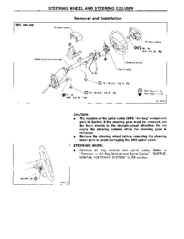
STEERING WHEEL AND STEERING COLUMN....1493
Removal and Installation....1493
Disassembly and Assembly....1495
Inspection....1496
POWER STEERING GEAR AND LINKAGE (Model PR26SE)....1497
Removal and Installation....1497
Disassembly....1500
Inspection....1500
Assembly....1501
Adjustment....1506
POWER STEERING OIL PUMP....1508
Disassembly and Assembly....1508
Pre-disassembly Inspection....1509
Disassembly....1509
Inspection....1510
Assembly....1510
TWIN ORIFICE POWER STEERING SYSTEM....1512
Hydraulic Circuit....1512
Schematic....1512
Wiring Diagram....1513
Trouble Diagnoses....1516
SERVICE DATA AND SPECIFICATIONS (SDS)....1525
General Specifications....1525
Inspection and Adjustment....1525
Infiniti Q45 (G50 Series) Service & Repair Manual 1991-1996
![]()