
John Deere PowerTech 8.1L Diesel Engines Component Technical Manual (CTM255)
Complete service repair manual with Electrical Wiring Diagrams for John Deere PowerTech 8.1L Diesel Engines, with all the technical information to maintain, diagnose, repair, and rebuild like professional mechanics.
John Deere PowerTech 8.1L Diesel Engines workshop service repair manual includes:
* Numbered table of contents easy to use so that you can find the information you need fast.
* Detailed sub-steps expand on repair procedure information
* Numbered instructions guide you through every repair procedure step by step.
* Troubleshooting and electrical service procedures are combined with detailed wiring diagrams for ease of use.
* Notes, cautions and warnings throughout each chapter pinpoint critical information.
* Bold figure number help you quickly match illustrations with instructions.
* Detailed illustrations, drawings and photos guide you through every procedure.
* Enlarged inset helps you identify and examine parts in detail.
CTM255 - John Deere PowerTech 8.1L Diesel Engines Level 9 Electronic Fuel System With Denso High Pressure Common Rail - (Worldwide Edition) Component Technical Manual.pdf
ctm256 - John Deere Motores diésel PowerTech™ 8.1 l Sistema de combustible electrónico Nivel 9 con Denso HPCR -: (Edición mundial).pdf
ctm257 - John Deere Moteurs diesel PowerTech™ 8,1 l Circuit d'alimentation électronique niveau 9 avec rampe commune haute pression Denso -: (Édition mondiale).pdf
ctm258 - John Deere Elektronisches Kraftstoffsystem Level 9 mit Denso-Hochdruck- Verteilerleiste für PowerTech™-8,1-l- Dieselmotoren -: (Weltweite Ausgabe).pdf
ctm262 - John Deere Дизельные двигатели PowerTech™ объемом 8,1 л Электронная топливная система уровня 9 с системой впрыска с общей топливной рампой Denso -: (Исполнение для всех стран).pdf
ctm263 - John Deere Sistema de Combustível Eletrônico Nível 9 de Motores Diesel PowerTech™ 8,1L com Trilho Comum de Alta Pressão Denso -: (Edição Mundial).pdf
ctm259 - John Deere Impianto di alimentazione elettronico per motori diesel PowerTech™ da 8,1 l livello 9 con Common Rail ad alta pressione Denso -: (Edizione universale).pdf
PRODUCT DETAILS:
Total Pages: 1,033 pages
File Format: PDF (Internal Links, Bookmarked, Table of Contents, Searchable, Printable, high quality)
Category: Component Technical Manual
Language: English Spanish French German Italian Russian Portuguese
TABLE OF CONTENTS
Section 01: General...18
Group 000: Safety...18
Handle Fluids Safely—Avoid Fires...21
Handle Starting Fluid Safely...22
Service Cooling System Safely...23
Prevent Battery Explosions...24
Prepare for Emergencies...25
Handling Batteries Safely...26
Wait Before Opening High-Pressure Fuel System...28
Avoid High-Pressure Fluids...29
Wear Protective Clothing...30
Service Machines Safely...31
Protect Against Noise...32
Work In Ventilated Area...33
Work in Clean Area...34
Remove Paint Before Welding or Heating...35
Avoid Heating Near Pressurized Fluid Lines...36
Illuminate Work Area Safely...37
Use Proper Lifting Equipment...38
Construct Dealer-Made Tools Safely...39
Practice Safe Maintenance...40
Use Proper Tools...42
Decommissioning — Proper Recycling and Disposal of Fluids and Components...43
Live With Safety...44
Group 001: Engine Identification...18
Engine Model Designation...47
Engine Serial Number Plate Information...49
Engine Option Code Label...51
Group 002: Fuels, Lubricants, and Coolant...18
Lubricants and Coolant...53
Diesel Fuel - Tier 1...54
Diesel Fuel - Tier 2...55
Diesel Fuel Additive Products...56
Handling and Storing Diesel Fuel...57
Bio-Diesel Fuel...58
Testing Diesel Fuel...59
Fuel Filters...60
Lubricity of Diesel Fuel...61
Section 02: Repair and Adjustments...62
Group 090: Electronic Fuel System Repair and Adjustments...62
Fuel System - General Information...65
Relieve Fuel System Pressure...66
Clean Primary Fuel Filter (Strainer) (—246269)...67
Remove and Install Fuel Filter Head (—246269)...69
Remove and Install Fuel Filter Heads (246270—)...71
Fuel Filter Assemblies (—246269)...73
Fuel Filter Assemblies (246270—)...76
Replace Final Fuel Filter Element (—246269)...77
Replacing Fuel Filter Elements (246270—)...80
Remove and Install High Pressure Fuel Pump Overflow Valve...83
Remove and Install Hand Primer...85
Remove High-Pressure Fuel Pump...87
Remove and Install High Pressure Common Rail...91
Remove and Install Flow Limiters...93
Remove and Install HPCR Pressure Relief Valve...96
Install High-Pressure Fuel Pump...98
Remove Electronic Injectors...102
Clean Electronic Injector Bore...105
Clean Electronic Injector Orifice...106
Clean Electronic Injector Body...107
Inspect Electronic Injector Body...108
Install Electronic Injectors...109
Clean Electronic injectors (In Engine)...115
Group 110: Electronic Engine Control Repair and Adjustment...62
Engine Control Unit (ECU)...204
Electronic Engine Control System and Sensors...119
Fuel Pump Sensors...121
Replace Coolant Temperature Sensor...122
Replace Fuel Temperature Sensor...123
Replace Crankshaft Position Sensor...124
Replace Manifold Air Temperature (MAT) Sensor...125
Replace Water in Fuel (WIF) Sensor...126
Remove and Install Oil Pressure Sensor...127
Remove and Install Fuel Rail Pressure Sensor...128
Connectors...129
Use Electrical Insulating Compound...130
Using High-Pressure Washer...131
Repair WEATHERPACK Connector...132
Remove Blade Terminals from Connector Body...135
Repair (Pull Type) METRI-PACK™ Connectors...136
Repair (Push Type) METRI-PACK™ Connectors...139
Repair DEUTSCH Connectors...142
Repair AMP Connector...145
Repair SUMITOMO™ Connectors...148
Repair YAZAKI™ Connectors...150
Section 03: Theory Of Operation...152
Group 130: Electronic Fuel System Operation...156
About This Group...376
Fuel System Operation...156
Primary Fuel Filter (Strainer) Operation (—246269)...159
Primary Fuel Filter Operation (246270—)...160
Fuel Transfer Pump Operation...162
Final Fuel Filter Operation (—246269)...164
Final Fuel Filter Operation (246270—)...166
High Pressure Fuel Pump Operation...168
High Pressure Common Rail (HPCR) Operation...170
Electronic Injector (EI) Operation...172
Group 140: Electronic Control System Operation...181
About This Group...376
Electronic Control System Terminology...179
Electronic Control System Operation...181
Electronic Control System Overview...182
Monitoring Engine Parameters...184
Measuring Temperature...185
Measuring Pressure...187
Measuring Engine Speed...189
Water In Fuel (WIF) Sensor...191
Throttle Descriptions...192
Digital Throttle Adjustments...197
Marine Throttles...199
Pump Control Valves (PCVs)...202
Electronic Injector (EI) Wiring Harness Connector...203
Engine Control Unit (ECU)...204
Controlled Area Network (CAN)...206
Pilot Injection Operation...207
Low-Idle Warmup...208
Intake Air Heater Operation...209
Charge Air Cooling Operation...210
Cruise Control Operation...211
Engine Derate and Shutdown Protection...212
Torque Curves...214
Governor Droop Modes...215
Engine Control Unit (ECU) Self-Diagnosis...216
Section 04: Diagnostics...217
Group 150: Observable Diagnostics and Tests...217
About This Group...376
E1 - Engine Cranks/Won't Start/Very Hard to Start (—246269)...217
E1--Engine Cranks/Wont'Start/Very Hard to Start (246270--)...217
E2 - Engine Misfires/Runs Irregularly...217
E3 - Engine Does Not Develop Full Power...217
E4 - Engine Emits Excessive White Exhaust Smoke...217
E5 - Engine Emits Excessive Black or Gray Exhaust Smoke...217
E6 - Engine Will Not Crank...217
E7 - Engine Idles Poorly...217
E8 - Abnormal Engine Noise...217
F1 - Fuel Supply System Check...217
F2 - Excessive Fuel Consumption...217
F3 - Fuel in Oil...217
F4 - Excessive Fuel Filter Replacement...280
ECU Does Not Communicate with Service ADVISOR...217
D1 - ECU Does Not Communicate with DST...217
D2 - Diagnostic Gauge (Earlier Model) Does Not Communicate With ECU...294
D2 - Diagnostic Gauge (Earlier Model) Does Not Communicate With ECU...294
D3 - Diagnostic Gauge (Later Model) Does Not Communicate With ECU...301
D3 - Diagnostic Gauge (Later Model) Does Not Communicate With ECU...301
A1 - Intake Air Heater Check...307
A1 - Intake Air Heater Check...307
Mechanical Compression Test...313
Check Fuel Supply Quality...315
Test for Air in Fuel...316
Check Fuel Supply Pressure...318
Check for Restricted Fuel Return Line...319
Bleed the Fuel System (—246269)...320
Restarting Engine That Has Run Out Of Fuel (—246269)...323
Bleed the Fuel System (246270—)...326
Electric Fuel Priming Pump...331
Bleed the Fuel System Using Electric Priming Pump (246270—)...333
Restarting Engine That Has Run Out of Fuel (246270—)...338
Check and Adjust High Pressure Fuel Pump Static Timing...340
Load Profile Information Test — Instructions...342
Electrical Concepts...346
Using a Digital Multimeter...347
Electrical Circuit Malfunctions...348
Troubleshooting Circuit Malfunctions...350
Primary CAN Diagnostic Procedure...218
Terminal Test...218
Diagnostic Test Box — Using...366
Group 160: Trouble Code Diagnostics and Tests...218
About This Group...376
Connecting to Diagnostic Scan Tool (DST)...377
Connecting to Service ADVISOR...381
Viewing Active DTCs on Diagnostic Gauge (Earlier Model)...383
Viewing Stored DTCs on Diagnostic Gauge (Earlier Model)...384
Clearing Stored DTCs on Diagnostic Gauge (Earlier Model)...385
Engine Configuration Parameters on Diagnostic Gauge (Earlier Model)...387
Viewing Active DTCs on Diagnostic Gauge (Later Model)...390
Viewing Stored DTCs on Diagnostic Gauge (Later Model)...393
Clearing Stored DTCs on Diagnostic Gauge (Later Model)...395
Data Parameters on Diagnostic Tools...396
Engine Test Instructions—Cylinder Misfire Test...401
Engine Test Instructions—Compression Test...403
Engine Test Instructions— Cylinder Cutout Test...404
Engine Test Instructions— Tractor Torque Curve Change Test...405
Engine Control Unit (ECU) — Donating this Engine’s ECU to be Used Elsewhere...406
Engine Control Unit (ECU) — Replacing Current ECU with Another ECU...410
Engine Control Unit (ECU) — Replacing Current ECU with Another ECU — Cannot Communicate with Current ECU...412
Engine Control Unit (ECU) — Reprogramming Current ECU...414
Engine Control Unit (ECU) — Reprogramming Instructions...415
Diagnostic Trouble Codes (DTCs)...417
List of Diagnostic Trouble Codes (DTCs) on ECU...418
Diagnostic Procedure Overview...425
Intermittent Fault Diagnostics...426
T1 - Multi-state Throttle Input High...427
T2 - Multi-state Throttle Input Low...431
T3 - Analog Throttle (A) Input High...434
T4 - Analog Throttle (A) Input Low...439
T5 - Analog Throttle (B) Input High...444
T6 - Analog Throttle (B) Input Low...449
T7 - CAN Throttle Invalid...454
T8 - PWM Throttle Input High...458
T9 - PWM Throttle Input Low...463
T10 - PWM Throttle Abnormal Pulse Width...468
T11 - Excavator Throttle Reference Voltage High...473
T12 - Excavator Throttle Reference Voltage Low...477
T13 - Excavator Throttle Ground Voltage High...481
T14 - Excavator Throttle Ground Voltage Low...485
T15 - Excavator Throttle Input Voltage High...489
T16 - Excavator Throttle Input Voltage Low...493
T22 - Analog Throttle (A) Input Voltage Out of Range...497
T23 - Multi-state Throttle Input Voltage Out of Range...498
000028.03 - Throttle Voltage High...219
000028.04 - Throttle Voltage Low...219
000029.03 - Throttle Voltage High...219
000029.04 - Throttle Voltage Low...219
000029.14 - Throttle Voltage Out of Range...219
000084.09 - Vehicle Speed Invalid or Missing...219
000091.03 - Throttle Voltage High...219
000091.04 - Throttle Voltage Low...219
000091.08 - PWM Throttle Abnormal Pulse Width...219
000091.09 - Throttle Invalid...219
000091.14 - Throttle Voltage Out of Range...219
000094.03 - Fuel Rail Pressure Input Voltage High...220
000094.04 - Fuel Rail Pressure Input Voltage Low...220
000094.10 - Fuel Rail Pressure Loss Detected...220
000094.17 - Fuel Rail Pressure Not Developed...220
000097.00 - Water in Fuel Continuously Detected...220
000097.03 - Water in Fuel Input Voltage High...220
000097.04 - Water in Fuel Input Voltage Low...220
000097.16 - Water in Fuel Detected...220
000097.31 - Water in Fuel Detected...220
000100.01 - Engine Oil Pressure Extremely Low...220
000100.03 - Engine Oil Pressure Input Voltage High...220
000100.04 - Engine Oil Pressure Input Voltage Low...220
000100.16 - Engine Oil Pressure Above Normal...220
000100.18 - Engine Oil Pressure Moderately Low...220
000102.03 - Manifold Air Pressure Input Voltage High...220
000102.04 - Manifold Air Pressure Input Voltage Low...220
000105.03 - Manifold Air Temperature Input Voltage High...220
000105.04 - Manifold Air Temperature Input Voltage Low...220
000105.16 - Manifold Air Temperature Moderately High...220
000107.00 - Air Filter Restriction...220
000110.00 - Engine Coolant Temperature Extremely High...220
000110.03 - Engine Coolant Temperature Input Voltage High...220
000110.04 - Engine Coolant Temperature Input Voltage Low...220
000110.15 - Engine Coolant Temperature High Least Severe...220
000110.16 - Engine Coolant Temperature Moderately High...220
000110.31 - Engine Coolant Temperature High...220
000111.01 - Engine Coolant Level Low...220
000158.17 - ECU Power Down Error...220
000160.02 - Wheel Speed Input Noise...220
000171.03 - Ambient Air Temperature Input Voltage High...220
000171.04 - Ambient Air Temperature Input Voltage Low...220
000174.00 - Fuel Temperature High Most Severe...220
000174.03 - Fuel Temperature Input Voltage High...220
000174.04 - Fuel Temperature Input Voltage Low...221
000174.16 - Fuel Temperature High Moderately Severe...221
000189.00 - Engine Speed Derate...221
000190.00 - Engine Overspeed Extreme...221
000190.01 - Engine Overload Moderate...221
000190.16 - Engine Overspeed Moderate...221
000190.18 - Engine Overload Severe...221
000237.02 - Vehicle Identification Number Invalid...221
000237.13 - Vehicle Identification Option Code Invalid...221
000237.31 - Vehicle Model Number Invalid...221
000523.09 - Gear Selection Invalid...221
000596.31 - Cruise Control On/Off Inputs Shorted...221
000611.03 - Electronic Injector Wiring Shorted To Power Source...221
000611.04 - Electronic Injector Wiring Shorted To Ground...221
000620.03 - Sensor Supply 1 Voltage High...221
000620.04 - Sensor Supply 1 Voltage Low...221
000627.01 - Electronic Injector Supply Voltage Problem...221
000629.13 - ECU Error...221
000636.02 - Pump Position Sensor Input Noise...221
000636.08 - Pump Position Sensor Input Missing...221
000636.10 - Pump Position Sensor Input Pattern Error...221
000637.02 - Crankshaft Position Input Noise...221
000637.07 - Crankshaft Position/Pump Position Timing Moderately Out of Sync...221
000637.08 - Crankshaft Position Input Missing...221
000637.10 - Crankshaft Position Input Pattern Error...221
000639.13 - CAN Bus Error...221
000640.31 - Engine Shutdown - Vehicle Request...221
000644.02 - External Speed Command Input Erratic...221
000651.05 - Cylinder #1 EI Circuit Open...221
000651.06 - Cylinder #1 EI Circuit Shorted...221
000651.07 - Cylinder #1 EI Fuel Delivery Failure...221
000652.05 - Cylinder #2 EI Circuit Open...221
000652.06 - Cylinder #2 EI Circuit Shorted...221
000652.07 - Cylinder #2 EI Fuel Delivery Failure...222
000653.05 - Cylinder #3 EI Circuit Open...222
000653.06 - Cylinder #3 EI Circuit Shorted...222
000653.07 - Cylinder #3 EI Fuel Delivery Failure...222
000654.05 - Cylinder #4 EI Circuit Open...222
000654.06 - Cylinder #4 EI Circuit Shorted...222
000654.07 - Cylinder #4 EI Fuel Delivery Failure...222
000655.05 - Cylinder #5 EI Circuit Open...222
000655.06 - Cylinder #5 EI Circuit Shorted...222
000655.07 - Cylinder #5 EI Fuel Delivery Failure...222
000656.05 - Cylinder #6 EI Circuit Open...222
000656.06 - Cylinder #6 EI Circuit Shorted...222
000656.07 - Cylinder #6 EI Fuel Delivery Failure...222
000898.09 - Vehicle Speed or Torque Message Invalid...222
000970.31 - Engine Shutdown - Auxiliary Request...222
000971.31 - External Fuel Derate Switch Active...222
001069.09 - Tire Size Invalid...222
001069.31 - Tire Size Error...222
001079.03 - Sensor Supply 2 Voltage High...222
001079.04 - Sensor Supply 2 Voltage Low...222
001080.03 - Fuel Rail Pressure Sensor Supply Voltage High...222
001080.04 - Fuel Rail Pressure Sensor Supply Voltage Low...222
001109.31 - Engine Protection Shutdown Warning...222
001110.31 - Engine Protection Shutdown...222
001347.05 - Pump Control Valve #1 Error...222
001347.07 - Fuel Rail Pressure Incorrect...222
001347.10 - Pump Control Valve #1 Fuel Flow Not Detected...222
001348.05 - Pump Control Valve #2 Error...222
001348.10 - Pump Control Valve #2 Fuel Flow Not Detected...222
001568.02 - Torque Curve Selection Invalid...222
001568.09 - Torque Curve Selection Missing...222
001569.31 - Fuel Derate...222
001638.00 - Hydraulic Oil Temperature High Most Severe...222
001638.03 - Hydraulic Oil Temperature Sensor Above Normal...223
001638.04 - Hydraulic Oil Temperature Sensor Voltage Below Normal...223
001638.16 - Hydraulic Oil Temperature High...223
001639.01 - Fan Speed Input Missing...223
001639.16 - Fan Speed Higher Than Expected...223
001639.18 - Fan Speed Lower Than Expected...223
002005.09 - ACU Signal Missing...223
002049.09 - Cab Signal Missing...223
002071.09 - CCU Signal Missing...223
002580.03 - Brake Pressure Sensor Voltage Above Normal...223
002580.04 - Brake Pressure Sensor Voltage Below Normal...223
Section 05: Tools...921
Group 170: Electronic Fuel/Control System Repair Tools and Other Materials...921
Group 090 - Electronic Fuel System Repair and Adjustment Essential Tools...925
Fuel System Repair and Adjustment Other Materials...928
Group 110 - Electronic Engine Control Repair Tools...929
Control Repair and Adjustment Other Materials...934
Group 180: Diagnostic Service Tools...921
JDE81-4...936
JDG820...937
JDG886...938
JDG1705...939
JDG10460...940
JDG10461...941
JDG10466...942
JDG11233...943
JDG11263...944
JT01674A...946
JT05412...947
JT07306...948
JT07328...949
Section 06: Specifications...950
Group 200: Repair Specifications...950
Unified Inch Bolt and Screw Torque Values...955
Metric Bolt and Screw Torque Values...957
General OEM Engine Specifications...959
Fuel System Component Torque Specifications...961
Engine Sensor Torque Specifications...963
Group 210: Diagnostic Specifications...950
Fuel System Diagnostic Specifications...965
Application Specifications...966
Articulated Dump Truck - Derate Specifications...968
Articulated Dump Trucks - Torque Curve Selection...969
Articulated Dump Trucks - Governor Mode Selection...970
Articulated Dump Trucks - ECU Terminal Identification...971
Cane Harvester - Derate Specifications...973
Cane Harvester - ECU Terminal Identification...974
Combines - Derate Specifications...976
Combines - Torque Curve Selection...977
Combines - Governor Mode Selection...978
Combines - ECU Terminal Identification...979
Crawler (Forestry) - Derate Specifications...981
Crawler (Forestry) - Torque Curve Selection...982
Crawler (Forestry) - Governor Mode Selection...983
Crawler (Forestry) - ECU Terminal Identification...984
Excavators - Derate Specifications...986
Excavators - Torque Curve Selection...987
Excavators - Governor Mode Selection...988
Excavators - ECU Terminal Identification...989
850/950 Feller Bunchers, Forwarders, and Harvesters (Forestry) - Derate Specifications...991
850/950 Feller Bunchers, Forwarders, and Harvesters (Forestry) - Torque Curve Selection...992
850/950 Feller Bunchers, Forwarders, and Harvesters (Forestry) - Governor Mode Selection...993
850/950 Feller Bunchers, Forwarders, and Harvesters (Forestry) - ECU Terminal Identification...994
Grader - Derate Specifications...996
Grader - Torque Curve Selection...997
Grader - Governor Mode Selection...998
Grader - ECU Terminal Identification...999
Loader - Derate Specifications...1001
Loader - Torque Curve Selection...1002
Loader - Governor Mode Selection...1003
Loader - ECU Terminal Identification...1004
OEM Engines - Derate Specifications...1006
OEM Engines - Torque Curve Selection...1008
OEM Engines - Governor Mode Selection With OC03040 Software or Later...1009
OEM Engines - Governor Mode Selection With OC03036 Software or Earlier...1010
OEM Engines - ECU Terminal Identification...1011
OEM Engines - ECU Terminal Identification - Continued...1013
Electronic Control System Wiring Diagram...1015
6081 OEM Application Instrument Panel/Engine Start Components Electrical Wiring Diagram...1016
6081 OEM Application Instrument Panel/Engine Start Components Electrical Wiring Diagram - Continued...1018
Self-Propelled Forage Harvester - Derate Specifications...1020
Self-Propelled Forage Harvester - Torque Curve Selection...1021
Self-Propelled Forage Harvester - Governor Mode Selection...1022
Self-Propelled Forage Harvester - ECU Terminal Identification...1023
Skidders (Forestry) - Derate Specifications...1025
Skidders (Forestry) - Torque Curve Selection...1026
Skidders (Forestry) - Governor Mode Selection...1027
Skidders (Forestry) - ECU Terminal Identification...1028
Sprayer - Derate Specifications...1030
Sprayer - Torque Curve Selection...1031
Sprayer - Governor Mode Selection...1032
Sprayer - ECU Terminal Identification...1033
Tractors - 7010 Series - Derate Specifications...1035
Tractors - 7010 Series - Torque Curve Selection...1036
Tractors - 7010 Series - Governor Mode Selection...1037
Tractors - 7010 Series - ECU Terminal Identification...1039
Tractors - 7020 Series - Derate Specifications...1041
Tractors - 7020 Series - Torque Curve Selection...1042
Tractors - 7020 Series - Governor Mode Selection...1043
Tractors - 7020 Series - ECU Terminal Identification...1044
Tractors - 8020 Series - Derate Specifications...1046
Tractors - 8020 Series - Torque Curve Selection...1047
Tractors - 8020 Series - Governor Mode Selection...1048
Tractors - 8020 Series - ECU Terminal Identification...1049
Tractors - 9120 Series - Derate Specifications...1051
Tractors - 9120 Series - Torque Curve Selection...1052
Tractors - 9120 Series - Governor Mode Selection...1053
Tractors - 9120 Series - ECU Terminal Identification...1054
6.8 L and 8.1 L OEM Application Electronic Control System Wiring Diagram...1056
8.1L Marine Application Electronic Control System Wiring Diagram...1057
6.8 L 6.8 L & 8.1 L OEM Application Instrument Panel/Engine Start Components Electrical Wiring Diagram{pgNO}952 8.1 L OEM Application Instrument Panel/Engine Start Components Electrical Wiring Diagram...1058
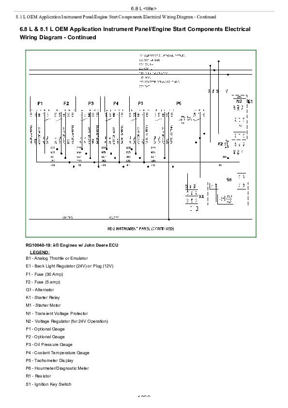
6.8 L 6.8 L & 8.1 L OEM Application Instrument Panel/Engine Start Components Electrical Wiring Diagram - Continued{pgNO}952 8.1 L OEM Application Instrument Panel/Engine Start Components Electrical Wiring Diagram - Continued...1060
John Deere PowerTech 8.1L Diesel Engines Component Technical Manual (CTM255)
![]()