
Case Crawler Excavators 850D, 855D Repair Service Manual

Case Crawler Excavators 850D, 855D Repair Service Manual
8-16520 - 850D, 855D Crawler Service Manual.pdf
Complete service repair manual with electrical wiring diagrams for Case Crawler Excavators 850D, 855D, with all the shop information to maintain, diagnose, repair, rebuild like professional mechanics.
Case Crawler Excavators 850D, 855D workshop service & repair manual includes:
* Numbered table of contents easy to use so that you can find the information you need fast.
* Detailed sub-steps expand on repair procedure information
* Numbered instructions guide you through every repair procedure step by step.
* Troubleshooting and electrical service procedures are combined with detailed wiring diagrams for ease of use.
* Notes, cautions and warnings throughout each chapter pinpoint critical information.
* Bold figure number help you quickly match illustrations with instructions.
* Detailed illustrations, drawings and photos guide you through every procedure.
* Enlarged inset helps you identify and examine parts in detail.
PRODUCT DETAILS:
Total Pages: 1,422 pages
File Format: PDF (bookmarked, ToC, Searchable, Printable, high quality)
Language: English
Case 850D 855D Crawler Excavator SECTIONS covered
GENERAL
Safety Rules, Service Manual Introduction, and Torque Specifications
Maintenance and Lubrication
General Engine Specifications
Detailed Engine Specifications
ENGINES
Engine and Radiator Removal and Installation
Engine Accessories (Air Cleaner, Ether Injection System,
Muffler, Turbocharger, and Torque Converter)
Engine Stall Tests
Cylinder Head and Valve Train
Cylinder Block, Pistons, Rods, Camshaft, Main Bearings,
Oil Seals, Flywheel and Crankshaft
Lubrication System
Cooling System
Turbocharger
Turbocharger Failure Analysis
FUEL SYSTEM
Fuel Lines, Fuel Tank, and Engine Controls
Fuel System and Filters
Bosch Fuel Injection Pump, Drive Gear, and Timing
Fuel Filters
ELECTRICAL
Removal and Installation of Electrical Components
Electrical System Specifications and Troubleshooting
Wiring Diagrams
Gauges
Batteries
Starter and Starter Solenoid
Delco-Remy Alternator
45 Amp Alternator A186124
45 Amp Alternator A187916
TRACK
Inspection of Track System Components
Case Lubricated Track
Standard Track and Track Frame
Idler, Track Adjuster, and Recoil Housing
Sprocket
Carrier Roller
Track Rollers
POWER TRAIN
Transmission/Torque Converter Diagram and Troubleshooting
Charging Pump
Transmission Control Valve
Modulator Valve
Removal and Installation of Torque Converter
Torque Converter
Transmission
Final Drive
Transmission Controls
Drive Shaft
BRAKES
Brake Pedals, Removal and Installation of Master Cylinder, Adjustment and
Removing Air From Brake System
Master Cylinder
Brake
HYDRAULICS
Hydraulic Diagrams, Troubleshooting and Pressure Checks
Cleaning the Hydraulic System
Rexroth Hydraulic Pump
Vickers Hydraulic Pump
Equipment Control Valve
Cylinders
Backhoe Control Valve
Removal and Installation of Stabilizer Control Valve
Stabilizer Control Valve
MOUNTED EQUIPMENT
Air Conditioning Troubleshooting
Air Conditioning System
Loader
Blade on Dozer Models
Ripper
ROPS Cab and Canopy
Operators Seat and Seat Belt
Suspension Seat
Backhoe
Winch
CONTENTS OF POCKET
Wiring Diagram
Hydraulic Schematic for Dozer
Hydraulic Schematic for Loader
Table of Contents
1 GENERAL
Safety Rules, Service Manual Introduction, and Torque Specifications ... 1001
Maintenance and Lubrication .. 1 002
General Engine Specifications ... 1010
Detailed Engine Specifications .. 1 024
2 ENGINES
Engine and Radiator Removal and Installation ... 2000
Engine Accessories (Air Cleaner, Ether Injection System,
Muffler, Turbocharger, and Torque Converter) .. 2001
Engine Stall Tests .. 2002
Cylinder Head and Valve Train .. 2415
Cylinder Block, Pistons, Rods, Camshaft, Main Bearings,
Oil Seals, Flywheel and Crankshaft ... 2425
Lubrication System ... 2445
Cooling System .. 2455
Turbocharger .. 2465
Turbocharger Failure Analysis ... 2565
3 FUEL SYSTEM
Fuel Lines, Fuel Tank, and Engine Controls ... 3001
Fuel System and Filters ... 3410
Bosch Fuel Injection Pump, Drive Gear, and Timing .. 3412
Fuel Filters .. 3413
4 ELECTRICAL
Removal and Installation of Electrical Components .. 4001
Electrical System Specifications and Troubleshooting .. : .. 4002
Wiring Diagrams ... 4003
Gauges ... 4004
Batteries ... 4005
Starter and Starter Solenoid ... 4006
Delco-Remy Alternator ... 4007
45 Amp Alternator A186124 ... 4008
45 Amp Alternator A 187916 ... 4009
5 TRACK
Inspection of Track System Components ... 5501
Case Lubricated Track ... 5504
Standard Track and Track Frame .. 5506
Idler, Track Adjuster, and Recoil Housing ... 5508
Sprocket ... 5509
Carrier Roller .. 5510
Track Rollers .. , ... 5511
CASE CORPORATION Bur 8-16520
6 POWER TRAIN
Transmission/Torque Converter Diagram and Troubleshooting ... 6002
Charging Pump .. 6005
Transmission Control Valve ... 6007
Modulator Valve ... 6008
Removal and Installation of Torque Converter .. 6009
Torque Converter ... 6010
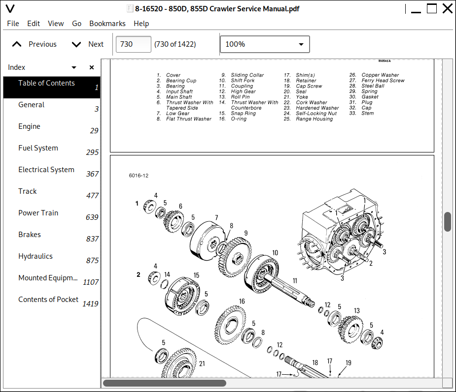
Transmission ... -... 6016
Final Drive .. 6017
Transmission Controls ... 6018
Drive Shaft .. 6021
7 BRAKES
Brake Pedals, Removal and Installation of Master Cylinder, Adjustment and
Removing Air From Brake System ... 7001
Master Cylinder .. 7002
Brake .. 7003
8 HYDRAULICS
Hydraulic Diagrams, Troubleshooting and Pressure Checks ... 8002
Cleaning the Hydraulic System .. 8003
Rexroth Hydraulic Pump .. 8005
Vickers Hydraulic Pump ... 8006
Equipment Control Valve ... 8007
Cylinders ... 8090
Backhoe Control Valve ... 8107
Removal and Installation of Stabilizer Control Valve ... 81 08
Stabilizer Control Valve .. 8109
9 MOUNTED EQUIPMENT
Air Conditioning Troubleshooting .. 9002
Air Conditioning System ... 9003
Loader .. 9010
Blade on Dozer Models ... 9020
Ripper ... 9031
ROPS Cab and Canopy ... 9061
Operators Seat and Seat Belt .. 9064
Suspension Seat .. 9065
Backhoe ... 91 00
Winch .. 9300
Wiring Diagram ... 850481
Hydraulic Schematic for Dozer ... 850609
Hydraulic Schematic for Loader ... 850610
Case Crawler Excavators 850D, 855D Repair Service Manual
![]()