
John Deere 468, 468 Silage Special, and 568 Round Balers Diagnosis and Repair Service Manual (TM1035)
Complete All Inclusive Technical Manual with electrical wiring diagrams for John Deere 468, 468 Silage Special, and 568 Round Balers, with workshop information to maintain, diagnose, repair, and rebuild like professional mechanics (Diagnosis, Operation, Tests, Repair, Service, Troubleshooting).
John Deere 468, 468 Silage Special, and 568 Round Balers workshop technical service manual includes:
* Numbered table of contents easy to use so that you can find the information you need fast.
* Detailed sub-steps expand on repair procedure information
* Numbered instructions guide you through every repair procedure step by step.
* Troubleshooting and electrical service procedures are combined with detailed wiring diagrams for ease of use.
* Notes, cautions and warnings throughout each chapter pinpoint critical information.
* Bold figure number help you quickly match illustrations with instructions.
* Detailed illustrations, drawings and photos guide you through every procedure.
* Enlarged inset helps you identify and examine parts in detail.
tm1035 - 468, 468 Silage Special, and 568 Round Balers Technical Manual.pdf
tm1035 - 468, 468 Silage Special, and 568 Round Balers Technical Manual.epub
PRODUCT DETAILS:
Total Pages: 1,211 pages
File Format: PDF/EPUB/MOBI/AZW (PC/Mac/Android/Kindle/iPhone/iPad; bookmarked, ToC, Searchable, Printable)
Language: English
TABLE OF CONTENTS
TABLE OF CONTENTS....1
Section 10: General....17
Group 05: Safety....17
Recognize Safety Information....20
Understand Signal Words....21
Follow Safety Instructions....22
Operate Baler Safely....23
Protect Bystanders....24
Handle Fluids Safely—Avoid Fires....25
Prepare for Emergencies....26
Fire Prevention....27
Fire Prevention—Welding....28
Avoid High-Pressure Fluids....29
Support Machine Properly....30
Wear Protective Clothing....31
Work in Clean Area....32
Service Machine Safely....33
Illuminate Work Area Safely....36
Replace Safety Signs....37
Use Proper Lifting Equipment....38
Remove Paint Before Welding or Heating....39
Avoid Heating Near Pressurized Fluid Lines....40
Service Tires Safely....41
Practice Safe Maintenance....42
Use Proper Tools....44
Construct Dealer-Made Tools Safely....45
Decommissioning — Proper Recycling and Disposal of Fluids and Components....46
Live With Safety....47
Group 10: Specifications....1186
468, 468 Silage Special, and 568 Round Baler Specifications....1186
Metric Bolt and Screw Torque Values....54
Unified Inch Bolt and Screw Torque Values....56
Face Seal Fittings Assembly and Installation—All Pressure Applications....58
Metric Face Seal Fitting Torque Chart—Standard Pressure Applications....59
Metric Face Seal Fitting Torque Chart—High Pressure Applications....61
SAE Face Seal Fitting Torque Chart—Standard Pressure Applications....63
SAE Face Seal Fitting Torque Chart—High Pressure Applications....65
Service Recommendations For 37° Flare and 30° Cone Seat Connectors....67
Group 15: General Information....18
Machine Description—468, 468 Silage Special, and 568....71
Group 20: Lubricants....18
Grease....74
Gear Case Oil....75
Alternative and Synthetic Lubricants....76
Mixing of Lubricants....77
Lubricant Storage....78
Perform Lubrication and Maintenance....79
Section 20: Drive Train....80
Group 05: General Information....80
Drive Train Operation....86
Operating RPM....88
Group 10: Diagnosing Malfunctions....587
PTO Driveline Difficulties....90
Adjust PTO and Pickup Slip Clutch Alert Sensors(MegaWide™ Plus and MegaTooth™ Pickups)....80
Slip Clutch Alert Feature (If Equipped)....97
Slip Clutch Difficulties (If Equipped)....98
Gear Case Difficulties....99
Drive Chain Difficulties....100
Group 15: Drive Train Protection....80
Service Parts Kits....433
Specifications....1186
Repair PTO Driveline Hub—Slip Clutch Type....104
Repair PTO Driveline Slip Clutch (If Equipped)....107
Adjust PTO Driveline Slip Clutch (If Equipped)....109
Slipping Seized PTO Driveline Slip Clutch (448 ONLY If Equipped)....111
Group 20: PTO Driveline....80
Other Material....1034
Service Parts Kits....433
Specifications....1186
PTO Driveline Exploded View—Slip Clutch Type....118
Repair PTO Lock-Back Collar Disconnect....120
Repair PTO Constant Velocity Joint....122
Replace Centralizer Bearing....129
Group 25: Remove and Install Gear Case....138
Essential or Recommended Tools....1184
Service Equipment and Tools....1205
Other Material....1034
Specifications....1186
Remove Gear Case....136
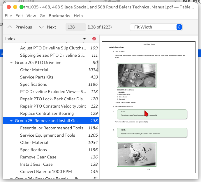
Install Gear Case....138
Convert Baler to 1000 RPM....145
Group 26: Gear Case Repair — Iberica....81
Essential or Recommended Tools....1184
Service Equipment and Tools....1205
Other Material....1034
Specifications....1186
Disassemble Iberica Gear Case....153
Inspect Iberica Gear Case....159
Assemble Iberica Gear Case....161
Group 27: Gear Case Repair — Comer....81
Essential or Recommended Tools....1184
Service Equipment and Tools....1205
Other Material....1034
Specifications....1186
Disassemble Comer Gear Case....174
Inspect Comer Gear Case....185
Assemble Comer Gear Case....187
Group 30: Roll Drives....81
Specifications....1186
Adjust Lower Drive Roll Chain....206
Adjusting Upper Drive Roll Chain (S.N.—370001)....207
Adjust Upper Drive Roll Chain (S.N. 370001—)....209
Check Starter Roll Drive Chain....211
Adjust Starter Roll Drive Chain....212
Replace Starter Roll Drive Chain....219
Check Upper Drive Roll Sprocket Alignment....221
Rotate or Replace Upper Drive Roll Chain Idler Bushing....224
Rotate or Replace Upper Drive Roll Chain Guides....225
Group 35: Rolls....81
Essential or Recommended Tools....1184
Service Equipment and Tools....1205
Other Material....1034
Specifications....1186
Diagram of Rolls and Belt Routing—468 and 568....232
Diagram of Rolls and Belt Routing—468S....234
Remove and Install Starter Roll....236
Remove and Install Belt Staggering Roll....246
Remove and Install Cleaning Auger Roll—468S....250
Checking and Adjusting Clearance Between Cleaning Auger and Staggered Belt Roll....253
Remove and Install Front Idler Roll....256
Remove and Install Take-Up Arm Roll....258
Remove and Install Top Idler Roll....260
Remove and Install Auxiliary Take-Up Roll....262
Remove and Install Upper Rear Gate Roll....263
Remove and Install Lower Rear Gate Roll....265
Remove and Install Lower Rear Gate Roll—With COVEREDGE Net Wrap....267
Remove and Install Lower Front Gate Roll....270
Remove and Install Rear Roll of Tension Arm....272
Remove and Install Center and Front Rolls of Tension Arm....274
Remove and Install Front Tension Arm Roll....276
Replace Tension Arm Roll Shaft....278
Replace Stationary Shaft Roll Bearings....281
Remove and Install Lower Drive Roll....284
Install Lower Drive Roll Bearings With Internal Threads Recessed 44 mm (1-3/4 in.) From Shaft End....295
Install Lower Drive Roll Bearings With Internal Threads—Starting at End of Shaft....310
Remove and Install Upper Drive Roll....326
Install Upper Drive Roll Bearings....335
High-Moisture Kit (Silage Baling) Difficulties....348
Group 40: Miscellaneous....82
Service Equipment and Tools....1205
Specifications....1186
Adjust Lower Front Gate Roll Scraper....354
Adjust Starter Roll Scraper (If Equipped)....356
Adjust Idler Roll Scraper (If Equipped)....358
Check for Twisted Gate....360
Check Belt Tracking....361
Adjust Belt Tracking without COVEREDGE Net Wrap....362
Adjusting Belt Tracking with COVEREDGE Net Wrap 2....364
Section 30: Hydraulics....369
Group 05: General Information....369
Hydraulic System Description and Diagram....373
Tensioning Valve....375
High Pressure Adjustable Relief Valve....376
High Pressure Relief Valve (Non Adjustable)....377
Low Pressure Relief Valve (Non Adjustable)....378
Pilot-Operated Check Valves....379
Optional Variable (Soft) Core Solenoid Valve....380
Install Inline Orifice Correctly....381
Bale Density Gauge....382
Group 10: Diagnosing Malfunctions....587
Diagnosing Hydraulic Malfunctions....386
Group 15: Operation and Tests....369
Essential or Recommended Tools....1184
Specifications....1186
Hydraulic System Operation....392
Low Pressure Relief Valve Test....398
Check Adjustable Relief Valve....400
Test Tension or Gate Cylinder for Leakage....402
Test Pickup Lift Cylinder for Leakage....405
Test Gate Lock Valve for Leakage....407
Group 20: Tensioning Valve Repair....369
Remove and Install Tensioning Valve....412
Disassemble and Inspect Tensioning Valve....415
Assemble Tensioning Valve....419
Check Condition of Valve Seat and Poppet....421
Install Check Valves Correctly....423
Group 25: Gate Lock Valve Repair....369
Repair Gate Lock Valve....427
Adjust Gate Lock Valve Interlock Lever (If Equipped)....430
Group 30: Cylinder Repair....369
Essential or Recommended Tools....1184
Service Parts Kits....433
Specifications....1186
Remove and Install Gate Cylinder....435
Disassemble and Assemble Tension Arm Cylinder....437
Disassemble and Assemble Gate Cylinder....448
Disassemble and Assemble Twine Arm Cylinder....462
Section 41: Twine Mechanism—Electric....469
Group 05: General Information....469
Twine Wrap System Description....552
Understanding Twine Wrap Terms and Settings....472
Group 10: Diagnosing Malfunctions....587
Twine Wrap Difficulties....483
BALETRAK Pro Monitor-Controller Difficulties....721
Group 15: Twine Wrap System Adjustments....469
Specifications....1186
Adjust Twine Arm-to-Starter Roll, Cutter Link Support, and Twine Arm Stop....499
Adjust Twine Cutter-to-Twine Arm....506
Check and Adjust Twine Cutter Knife....509
Adjust Twine Cutter Contact Tab....513
Adjust Clearance Between Cutter Link Support and Twine Arm....516
Adjust Twine Cutter Tension....518
Adjust Front Twine Arm....523
Adjust Twine Indicator Retaining Strap....526
Set Twine End Wrap Distance....527
Set Twine Spacing....530
Group 20: Twine Wrap System Repair....469
Specifications....1186
Remove and Install Twine Arm Actuator—468 and 468S....534
Install Twine Arm Actuator, Adapter, and Pivot Assembly—468 and 468S....536
Remove and Install Twine Arm Actuator—568....539
Install Twine Arm Actuator, Adapter, and Pivot Assembly—568....541
Install Twine Arm Stop—468 and 468S....543
Install Twine Arm Stop—568....544
Install Twine Arm and Twine Arm Drive Gear—568....545
Section 50: COVEREDGE Net Wrap System (If Equipped)....547
Group 05: General Information....547
Other Material....1034
Specifications....1186
System Description....552
Switch Description....553
Setting Number of Net Wraps (If Equipped)....554
Correct Feeding Problems....556
Using Net Wrap After Extended Storage....559
Check and Adjust Net Wrap Pan....565
Check and Straighten Net Pan Angle....570
Checking and Adjusting Net Pan Pressure without Leaf Spring....572
Group 10: Diagnosing Malfunctions....587
Diagnosing Malfunctions....587
BALETRAK Pro Monitor-Controller Difficulties....721
Group 15: Net Wrap Repair....547
Essential or Recommended Tools....1184
Specifications....1186
Remove and Install Net Wrap Assembly....604
Repair Cuts on Feed Roll....608
Remove and Install Upper (Rubber) Feed Roll....609
Replace Upper Feed Roll Bearings....613
Remove and Install Lower (Steel) Feed Roll....614
Remove and Install Lower Net Wrap Guide....616
Adjust Lower Net Wrap Guide....620
Check Net Pan Pressure....623
Replace Lower Front Gate Roll Belt Guide....626
Replace Cover Hinge Seal....630
Check Cover Gas Springs....631
Check and Adjust Cover Latch....633
Remove Net Wrap Actuator....635
Install Net Wrap Actuator....637
Remove and Install Net Wrap V-Belt....639
Check and Adjust Net Wrap V-Belt Idler Tension....643
Check and Adjust Net Wrap Switch....649
Replace Net Wrap Switch or Switch Arm....652
Remove and Install Cutoff Knife....654
Sharpen Cutoff Knife....658
Adjust Net Wrap Counterknife....659
Install and Adjust Net Wrap Brush....665
Checking and Adjusting Brake Pad....668
Checking and Adjusting Net Wrap Feed Roll Brake Spring....671
Adjusting Net Wrap Feed Roll Pressure....672
Adjusting Net Wrap Stretch....674
Section 60: Electrical System....676
Group 05: General Information....676
Electrical System Description—BALETRAK Pro....687
Slip Clutch Alert (If equipped)....694
Tail Lights and Warning Lights....696
Lighting Enhancement Module Operation....697
Group 10: Common Electrical Tests and Checks....676
Service Equipment and Tools....1205
Electromagnetic Interference (EMI)....700
Basic Informational Warnings for Machines Equipped With Computer Controlled Systems....701
Checks Before Testing....702
Electrical Circuit Definition....703
Electronic Circuit Definition....704
Common Circuit Test....706
Electrical Circuit Malfunctions....707
Probe Light Check—Voltage from Battery....711
Probe Light Check—Continuity to Ground....712
Seven-Step Electrical Test Procedure....713
Group 15: Diagnosing Malfunctions—BALETRAK Pro System....676
Activating BaleTrak™ Pro Monitor-Controller Alarms....716
BALETRAK Pro Monitor Error Codes....717
BALETRAK Pro Monitor-Controller Difficulties....721
Group 20: Tests and Adjustments—BALETRAK Pro System....676
Specifications....1186
Access BaleTrak™ Pro Customer, Setup, and Diagnostic Channels....733
BALETRAK Pro Monitor-Controller Customer Channels....736
Channel 001: Reset BaleTrak Pro Monitor-Controller To Initial Settings....737
Channel 002: Dry Straw Twine Wrap Program....738
Channel 003: Set Twine Re-Extension....739
Channel 004: Set Cinch Wrap....741
Channel 005: Adjust Bale Diameter Sensor....742
Adjusting Bale Diameter Display....745
Channel 006: Adjust Net Wrap Delay....747
Channels 007 and 009: Adjust Bale Shape Sensor....748
Channels 007 and 009: Adjust Bale Shape Bar Display—Field Procedure....751
Channel 008: Change Display to Metric or English Units....753
Channel 010: Set Near-Full Indicator Set Point....754
Channel 011: Set Bale Shape Sensitivity....756
Channel 012: Test Net Wrap Switch....758
Channels 013, 014 and 015 Gate Latch and Oversize Bale Switches—Monitor-Controller Assisted Test....760
Remove and Install Gate Latch Proximity Switches....1160
Adjust Gate Latch Proximity Switches....1161
Adjust Oversize Bale Switch....765
Channels 016 and 017: Checking PTO and Pickup Speed....767
Adjust PTO and Pickup Speed Sensors....769
Channel 018: Test Twine or Net Wrap Actuator Current....771
Channel 019: Test Tractor Convenience Outlet Voltage....773
Channel 020: Test Liquid Crystal Display (LCD) Panel....775
Channel 029: Calibrate Twine Arm....776
Channel 033: Adjust Delay of Twine Eject....778
Checking Microswitches....779
Test Mechanical Sensors....780
Test “Hall Effect” Sensors....781
BALETRAK Pro Monitor-Controller Setup Channels....783
Channel 201: Change Baler Model....784
Channel 202: Enable Twine Feature....786
Channel 203: Enable Net Wrap Feature....788
Channel 204: Slip Clutch Alert PTO Speed Sensor....790
Channel 205: Slip Clutch Alert Pickup RPM Sensor....792
Channels 206 and 207: Calibrate Slip Clutch Alert PTO and Pickup RPM Sensors....794
Channel 208: Activating Optional Variable Core Operation....797
BALETRAK Pro Monitor-Controller Diagnostic Channels....799
Channels 301—306: Diagnostic Trouble Codes and Bale Count Memory....800
Channel 307: View Minutes Counter....804
Channel 308: View Hours Counter....805
Channel 309: Lowest Battery Voltage Level Recorded....806
Channel 310: Highest Battery Voltage Level Recorded....808
Channel 311: Controller Software Version....810
Channel 312: Total Bale Counter....811
Group 25: Electrical Diagrams—BALETRAK Pro System....678
BaleTrak™ Pro Component Locations....813
Wiring Harness Diagram—BaleTrak Pro Monitor-Controller....814
Electrical Schematic....818
Group 30: BALETRAK Pro Monitor-Controller Operations....678
BALETRAK Pro Monitor-Controller Keys and Switches....821
BaleTrak™ Pro Monitor-Controller Displays and Indicators....822
BaleTrak™ Pro Monitor-Controller Operation....823
BaleTrak™ Pro Monitor-Controller Specifications....1186
BaleTrak™ Pro Monitor-Controller Setup Values and Initial Settings....826
Viewing and Resetting Bale Counters....828
Adjusting Audible Alarm Volume....830
Using Manual Actuator, Wrap, and Bypass Switches....831
Using Bypass Switch (Twine Wrap Only)....833
Group 35: Repair—BALETRAK Pro System....678
Specifications....1186
Programming BaleTrak™ Pro....836
Replace Monitor-Controller LCD Backlight Bulbs....837
Replace Monitor-Controller LCD Panel....838
Replace BaleTrak™ Pro Monitor-Controller Faceplate....841
Replace Monitor-Controller Audible Alarm....844
Replace Bale Diameter Sensor....845
Replace Bale Shape Sensor....847
Replace Oversize Bale Switch....849
Replace Variable (Soft) Core Solenoid Coil (If Equipped)....850
Replace BaleTrak™ Pro Computer Chip (EEPROM)....851
Resetting BaleTrak™ Pro Monitor-Controller To Initial Settings (Channel 001)....855
Group 40: Connector Repair....678
Essential or Recommended Tools....1184
Other Material....1034
Electrical Connector Handling....861
Use Terminal Cleaner and Di-Electric Grease....862
Connector Identification....863
Replace WEATHER PACK Connector....865
Install WEATHER PACK Terminal....867
Remove Connector Body from Blade Terminals....869
Replace DEUTSCH Connectors....870
Install DEUTSCH Terminal Connectors....872
Replace CPC Blade Type Connectors....874
Replace Small MATE-N-LOC Pin Connector....875
Section 70: Pickup....876
Group 05: General Information....876
Pickup Description....880
Preliminary Checks....881
Check Pickup Tooth End Play....883
Group 10: Diagnosing Malfunctions....587
Pickup Difficulties....890
Feeding Difficulties....894
General Baler Difficulties....899
Group 15: Regular Pickup Repair....876
Service Equipment and Tools....1205
Other Material....1034
Specifications....1186
Replace Teeth (Pickup Installed)....1066
Replace Cam Follower Bearings....1070
Remove and Install Pickup....1073
Disassemble Pickup....1081
Inspect Pickup Components....1090
Assemble Pickup....1093
Pickup Drive Belt and Chain Alignment....960
Adjust Initial Length of Drive Belt Idler Spring....962
Adjust Drive Belt Idler....963
Adjust Pickup Float Springs....1118
Group 20: MEGATOOTH Pickup Repair (568 Only)....876
Service Equipment and Tools....1205
Other Material....1034
Specifications....1186
Replace Teeth (Pickup Installed)....1066
Replace Cam Follower Bearings—Left-Hand Side....975
Replace Cam Follower Bearings—Right-Hand Side....982
Remove and Install Pickup....1073
Disassemble Pickup....1081
Inspect Pickup Components....1090
Assemble Pickup....1093
Pickup Drive Chains Alignment....1111
Adjust Float Springs....1030
Group 25: MEGAWIDE PLUS Pickup Repair....877
Service Equipment and Tools....1205
Other Material....1034
Specifications....1186
Remove and Install Roller Baffle....1037
Repair Roller Baffle....1040
Balancing Roller Baffle....1047
Removing Compressor Rack Assembly (MEGAWIDE PLUS)....1049
Installing Compressor Rack Assembly (MEGAWIDE PLUS)....1050
Remove and Install MEGAWIDE PLUS Pickup/Rotor Assembly....1051
MEGAWIDE PLUS Pickup/Rotor Frame-to-Baler Frame Shimming Procedure....1062
Replace Teeth (Pickup Installed)....1066
Replace Cam Follower Bearings....1070
Remove and Install Pickup....1073
Disassemble Pickup....1081
Inspect Pickup Components....1090
Assemble Pickup....1093
Remove and Install Auger/Rotor Assembly....1108
Disassemble and Assemble Auger/Rotor Assembly....1110
Pickup Drive Chains Alignment....1111
Adjust Auger Scrapers....1114
Adjust Pickup Drive Chains....1115
Adjust Pickup Float Springs....1118
Group 30: Miscellaneous....877
Service Equipment and Tools....1205
Specifications....1186
Adjust Initial Length of Hydraulic Lift Cylinder (If Equipped)....1123
Check Slip Clutch Torque (MEGAWIDE PLUS)....1124
Remove and Install Pickup Slip Clutch....1128
Repair Gauge Wheel—Regular and MEGATOOTH Pickups....1130
Repair Gauge Wheel—MEGAWIDE PLUS Plus Pickup....1132
Section 80: Miscellaneous....1134
Group 05: Wheel Repair....1134
Service Equipment and Tools....1205
Specifications....1186
Remove and Install Baler Wheel....1139
Inspect and Replace Baler Wheel Bearings—21.5L X 16.1 Tires....1141
Inspect and Replace Baler Wheel Bearings—31 X 13.5-15 Tires....1143
Repair Gathering Wheel (If Equipped)....1145
Remove Excessive Play from Gathering Wheel Pivot....1148
Group 10: Gate Repair....1134
Specifications....1186
Straighten Gate....1152
Remove and Install Gate....1155
Remove and Install Gate Latch Proximity Switches....1160
Adjust Gate Latch Proximity Switches....1161
Group 15: Tension Arm Repair....1134
Specifications....1186
Remove and Install Tension Arm....1165
Adjust Take-Up Arm Spring....1171
Adjust Bale Size Indicator....1172
Inspect Tension Arm Wear Channel....1173
Replace Tension Arm Wear Channel....1175
Group 20: Tongue Repair....1134
Specifications....1186
Remove and Install Tongue....1179
Group 25: Belt Repair....1134
Essential or Recommended Tools....1184
Service Equipment and Tools....1205
Specifications....1186
Remove Belts....1187
Install Belts....1188
Prepare Belts For New Lacings....1192
Install Belt Lacing....1196
Belts Eligible for Warranty Replacement....1200
Belts Not Eligible for Warranty Replacement....1201
Group 30: Main Frame Repair....1135
Service Equipment and Tools....1205
Straighten Main Frame 468 (—362900) 468S (—362400) 568 (—365000)....1206
Straighten Main Frame 468 (362901—) 468S (362401—) 568 (365001—)....1212
Section 99: Dealer Fabricated Tools....1218
Group 05: Dealer Fabricated Tools....1218
DFEX1874A Support Strap....1220
John Deere 468, 468 Silage Special, and 568 Round Balers Diagnosis and Repair Service Manual (TM1035)
![]()