
Komatsu Hydraulic Excavator PC118MR Repair Service Manual
Complete service repair manual with Electrical Wiring Diagrams for Komatsu Hydraulic Excavator PC118MR, with all the technical information to maintain, diagnose, repair, and rebuild like professional mechanics.
Komatsu Hydraulic Excavator PC118MR workshop service repair manual includes:
* Numbered table of contents easy to use so that you can find the information you need fast.
* Detailed sub-steps expand on repair procedure information
* Numbered instructions guide you through every repair procedure step by step.
* Troubleshooting and electrical service procedures are combined with detailed wiring diagrams for ease of use.
* Notes, cautions and warnings throughout each chapter pinpoint critical information.
* Bold figure number help you quickly match illustrations with instructions.
* Detailed illustrations, drawings and photos guide you through every procedure.
* Enlarged inset helps you identify and examine parts in detail.
WEBM008700 - Hydraulic Excavator PC118MR-8 Shop Manual.pdf
PRODUCT DETAILS:
Total Pages: 872 pages
File Format: PDF (Internal Links, Bookmarked, Table of Contents, Searchable, Printable, high quality)
Language: English
00 Index and foreword...3
Table of contents...4
Foreword and general information...12
Safety notice...12
How to read the shop manual...17
Explanation of terms for maintenance standard...19
Handling of hydraulic components...21
Method of disconnecting and connecting push-pull type coupler...23
Handling of electric equipment...26
How to read electric wire code...36
Precautions when performing work...39
Standard tightening torque table...42
List of abbreviation...46
Conversion table...50
Shop Manual...55
01 Specification...55
Contents...56
Specifications...57
Specifications drawing...57
Specifications...60
Table of weight...63
Table of fuel, coolant and lubricants...65
Shop Manual...67
10 Structure and function...67
Contents...68
Engine and cooling system...70
Engine mount...70
PTO...71
Cooling system...72
Power train...74
Power train...74
Swing circle...75
Swing machinery...76
Undercarriage and frame...77
Track frame...77
Idler and recoil spring...78
Carrier roller...79
Track roller...80
Track shoe...81
Hydraulic system...82
Hydraulic equipment layout drawing...82
Valve control...83
Hydraulic tank and filter...84
Hydraulic pump...86
Blade specification...86
Control valve...98
Outline...98
11-spool valve...99
CLSS...110
Outline of CLSS...110
Basic principle...111
Function and operation by valve...114
Hydraulic circuit diagram and name of valves...114
1. Unload valve...116
2. Introduction of LS pressure...119
3. LS bypass plug...121
4. Pressure compensation valve...122
5. Surface area ratio of pressure compensation valve...123
6. Right and left travel junction circuit...124
7. Travel LS bypass circuit...126
8. Boom regeneration circuit...128
PPC valve...131
Work equipment and swing PPC valve...131
Travel PPC valve...137
Blade and boom swing PPC valve...140
Swing motor...142
Safety valve with suction...144
Operation of the modulating relief valve...145
Operation of swing brake...146
Actuation of hydraulic timer valve...147
Travel motor...148
Center swivel joint...150
Solenoid valve...151
Attachment oil flow adjuster EPC valve...152
PPC accumulator...156
For PPC circuit...156
Anti-drop valve...157
Work equipment...163
Work equipment...163
Dimensions of components...166
1,850 mm arm...166
2,000 mm arm...168
2,300 mm arm...170
Bucket...172
Work equipment cylinder...174
Boom cylinder...174
2-piece boom cylinder...174
Arm cylinder...174
Bucket cylinder...175
Boom swing cylinder...175
Blade cylinder...175
Cab and its attachments...178
Air conditioner...178
Air conditioner piping diagram...178
Air conditioner unit...182
Air conditioner controller...185
Compressor...186
Condenser...187
Sensor...188
Electrical system...189
Electrical control system...189
Machine control system diagram...189
Engine control function...191
Engine and pump mutual control function...193
Auto-deceleration function...197
Engine automatic warm-up function...199
Swing control function...203
Travel control function...205
PPC lock function...207
Oil flow adjuster function for attachment...208
System components...210
Monitor system...219
Machine monitor...220
Display...222
Switches...226
Operator mode function...230
Service mode function...232
KOMTRAX system...233
Sensor...236
Atmospheric pressure sensor...236
Boost pressure and temperature sensor...236
Coolant temperature sensor...237
Crankshaft speed sensor...237
Common rail pressure sensor...238
Hydraulic oil temperature sensor...238
Fuel level sensor...239
Pump oil pressure sensor...240
PPC oil pressure sensor...241
Shop Manual...243
20 Standard value table...243
Contents...244
Standard value table...245
Standard value table for engine...245
Standard value table for chassis...246
30 Testing and adjusting...255
Contents...256
Testing and adjusting...257
Testing engine speed...257
Testing exhaust temperature...258
Checking exhaust gas colour...259
Adjusting valve clearance...260
Testing compression pressure...262
Testing blow-by pressure...264
Testing engine oil pressure...265
Handling fuel system parts...266
Releasing residual pressure from fuel system...266
Testing fuel pressure...267
Testing fuel return rate and fuel leakage...268
Bleeding air from fuel circuit...270
Checking fuel circuit for leakage...272
Testing and adjusting alternator belt tension...273
Testing...273
Adjusting...273
Measuring the swing circle axial clearance...274
Testing and adjusting track-shoe tension...275
Checking and regulating pressure in the hydraulic circuits...276
Testing and adjusting oil pressure in work equipment and travel circuits...277
Testing and adjusting swing and blade circuit oil pressure...279
Testing control circuit basic pressure...281
Testing and adjusting oil pressure in pump PC control circuit...282
Testing LS differential pressure and adjusting LS valve...284
Testing solenoid valve output pressure...286
Testing main pump flow rate...289
Checking parts which cause hydraulic drift of work equipment...290
Measuring travel deviation...292
Adjusting the maximum speed of the travel motors...293
Releasing residual pressure from hydraulic circuit...294
Testing oil leakage...295
Air bleeding from hydraulic circuits...298
Order for operations...298
Special functions of machine monitor...300
Handling voltage circuit of engine controller...349
Preparation work for troubleshooting of electrical system...350
Procedure for testing diodes...355
Pm Clinic service...356
40 Troubleshooting...361
Contents...362
Failure code table and fuse locations...366
Failure code table...366
Fuse locations...369
General information on troubleshooting...371
Points to remember when troubleshooting...371
Sequence of events in troubleshooting...372
Checks before troubleshooting...373
Classification and procedures for troubleshooting...374
Information in troubleshooting table...375
Phenomena looking like troubles and troubleshooting Nos...377
Connection table for connector pin numbers...380
T- branch box and T- branch adapter table...416
Troubleshooting by failure code...419
Failure code [989L00] Engine controller lock caution 1...419
Failure code [989M00] Engine controller lock caution 2...420
Failure code [989N00] Engine controller lock caution 3...421
Failure code [AB00KE] Charge voltage low...422
Failure code [B@BAZG] Eng oil press. low...424
Failure code [B@BCNS] Eng coolant overheat...425
Failure code [B@HANS] Hyd. oil overheat...426
Failure code [CA111] ECM critical internal failure...427
Failure code [CA115] Eng. Ne and Bkup speed sensor error...430
Failure code [CA122] Charge air press sensor high error...431
Failure code [CA123] Charge air press sensor low error...433
Failure code [CA131] Throttle sensor high error...434
Failure code [CA132] Throttle sensor low error...436
Failure code [CA144] Coolant temp. sensor high error...438
Failure code [CA145] Coolant temp. sensor low error...440
Failure code [CA153] Charge air temp. sensor high error...442
Failure code [CA154] Charge air temp. sensor low error...444
Failure code [CA155] Charge air temperature high speed derate...445
Failure code [CA187] Sensor sup. 2 volt. low error...446
Failure code [CA221] Ambient air press. sensor high error...448
Failure code [CA222] Ambient air press. sensor low error...450
Failure code [CA234] Eng. overspeed...451
Failure code [CA238] Ne speed sensor sup. volt. error...452
Failure code [CA271] IMV/PCV1 short error...454
Failure code [CA272] IMV/PCV1 open error...455
Failure code [CA322] Injector #1 (L #1) system open/short error...456
Failure code [CA324] Injector #3 (L #3) system open/short error...458
Failure code [CA331] Injector #2 (L #2) system open/short error...460
Failure code [CA332] Injector #4 (L #4) system open/short error...462
Failure code [CA342] Calibration code incompatibility...464
Failure code [CA351] Inj. drive circuit error...465
Failure code [CA352] Sensor sup. 1 volt. low error...468
Failure code [CA386] Sensor sup. 1 volt. high error...470
Failure code [CA435] Abnormality in engine oil pressure switch...472
Failure code [CA441] Battery voltage low error...473
Failure code [CA442] Battery voltage high error...474
Failure code [CA449] Rail press. very high error...475
Failure code [CA451] Rail press. sensor high error...476
Failure code [CA488] Charge air temperature high torque derate...478
Failure code [CA452] Rail press. sensor low error...479
Failure code [CA553] Rail press. high error...480
Failure code [CA559] Rail press. low error...481
Failure code [CA689] Eng. Ne speed sensor error...484
Failure code [CA731] Eng. Bkup speed sensor phase error...486
Failure code [CA757] All persistent data lost error...487
Failure code [CA778] Eng. Bkup speed sensor error...488
Failure code [CA1633] KOMNET datalink timeout error...490
Failure code [CA2185] Throttle sens. sup. volt. high error...492
Failure code [CA2186] Throttle sens. sup. volt. low error...494
Failure code [CA2249] Rail press. very low error...495
Failure code [CA2311] Abnormality in IMV solenoid...496
Failure code [D110KB] Battery relay drive short...498
Failure code [D19JKZ] Personal code relay abnormality...500
Failure code [D862KA] GPS antenna discon...502
Failure code [DA22KK] Pump solenoid power low error...504
Failure code [DA25KP] 5 V sensor 1 power abnormality...507
Failure code [DA26KP] 5 V sensor 2 power abnormality...510
Failure code [DA2RMC] CAN discon (Pump controller detected)...512
Failure code [DAF8KB] Camera Power Supply Short Circuit...514
Failure code [DAFGMC] GPS module error...516
Failure code [DAFRMC] CAN discon (Monitor detected)...518
Failure code [DFB1KZ] Service lever pot. 1 abnormality...520
Failure code [DFB2KZ] Service lever pot. 2 abnormality...522
Failure code [DFB3L8] Service lever1 potentio error...524
Failure code [DFB4L8] Service lever2 potentio error...526
Failure code [DFB5KZ] Service lever sPot. 1 abnormality...528
Failure code [DFB6KZ] Service lever sPot. 2 abnormality...530
Failure code [DGH2KB] Hydr oil sensor short...532
Failure code [DHPAMA] Pump press sensor abnormality...534
Failure code [DHS5KX] Travel PPC sensor abnormality...536
Failure code [DHX1MA] Overload sensor abnormality...538
Failure code [DV20KB] Travel alarm short circuit...539
Failure code [DW43KA] Travel speed sol discon...540
Failure code [DW43KB] Travel speed sol short...541
Failure code [DW45KA] Swing brake sol discon...542
Failure code [DW45KB] Swing brake sol short...544
Failure code [DXA8KA] PC-EPC sol discon...546
Failure code [DXA8KB] PC-EPC sol short...548
Failure code [DXE7KA] Service current EPC2 open circuit...550
Failure code [DXE7KB] Service current EPC2 short circuit...552
Failure code [DXE8KA] Service current EPC3 open circuit...554
Failure code [DXE8KB] Service current EPC3 short circuit...556
Failure code [DXE9KA] Service current EPC4 open circuit...558
Failure code [DXE9KB] Service current EPC4 short circuit...560
Failure code [DXEAKA] Service current EPC1 open circuit...562
Failure code [DXEAKB] Service current EPC1 short circuit...564
Failure code [DY20KA] Wiper working abnormality...566
Failure code [DY20MA] Wiper parking abnormality...568
Failure code [DY2CKA] Washer drive open circuit...570
Failure code [DY2CKB] Washer drive short circuit...572
Failure code [DY2DKB] Wiper drive (fwd) short circuit...574
Failure code [DY2EKB] Wiper drive (rev) short circuit...576
Troubleshooting of electrical system...579
Before carrying out troubleshooting of electrical system...579
Information in troubleshooting table...581
E-1 When starting switch is turned ON, machine monitor displays nothing...582
E-2 Engine does not start (Engine does not turn)...585
E-3 Preheater does not operate...588
E-4 Automatic warm-up system does not operate (in cold season)...590
E-5 All work equipment, swing, and travel mechanism do not move or cannot be locked...591
E-6 Precaution lights up while engine is running...594
E-7 Emergency stop item lights up while engine is running...597
E-8 Engine coolant temperature gauge does not indicate normally...598
E-9 Hydraulic oil temperature gauge does not indicate normally...600
E-10 Fuel level gauge does not indicate normally...603
E-11 Contents of display by machine monitor are different from applicable machine...605
E-12 Machine monitor does not display some items...606
E-13 Function switch does not work...607
E-14 Auto-decelerator does not operate normally...608
E-15 Working mode does not change...609
E-16 Travel speed does not change...610
E-17 Alarm buzzer cannot be stopped...611
E-18 Windshield wiper and window washer do not operate...612
E-19 Swing holding brake does not operate normally...616
E-20 Travel alarm does not sound or does not stop sounding...618
E-21 Air conditioner does not operate normally (including air conditioner abnormality record)...619
E-22 While starting switch is in OFF position, service meter is not displayed...632
E-23 Machine monitor cannot be set in service mode...633
E-24 Monitoring function does not display lever control signal normally...634
E-25 KOMTRAX system does not operate normally...658
Troubleshooting of hydraulic and mechanical system (H-mode)...659
Information contained in troubleshooting table...659
H-1 Speed or power of all work equipment, swing, and travel are low...660
H-2 Engine speed sharply drops or engine stalls...661
H-3 No work equipment, travel and swing move...662
H-4 Abnormal noise is heard from around hydraulic pump...663
H-5 Fine control performance or response of work equipment and travel is low...664
H-6 Speed or power of boom is low...665
H-7 Speed or power of arm is low...666
H-8 Speed or power of bucket is low...667
H-9 Speed or power of boom swing is low...668
H-10 Speed or power of blade is low...669
H-11 Work equipment does not move in its single operation...670
H-12 Hydraulic drift of work equipment is large...671
H-13 Time lag of work equipment is large...673
H-14 Work equipment loaded more is slower during compound operation...674
H-15 Boom RAISE speed is low in compound operation of swing + boom RAISE...675
H-16 Travel speed lowers significantly during compound operation of work equipment/swing + travel...676
H-17 Machine deviates during travel...677
H-18 Travel speed is low...678
H-19 Machine cannot be steered easily or steering power is low...679
H-20 Travel speed does not change or it is kept low or high...680
H-21 Track does not move (only either side)...681
H-22 Machine does not swing...682
H-23 Swing acceleration, swing speed and swing power are low...683
H-24 Excessive overrun when stopping swing...685
H-25 When upper structure stops swinging, it makes large shock...686
H-26 When upper structure stops swinging, it makes large sound...687
H-27 Hydraulic drift of swing is large...688
H-28 Flow rate in attachment circuit cannot be adjusted...689
Troubleshooting of engine (S-mode)...690
Method of using troubleshooting chart...690
S-1 Starting performance is poor...694
S-2 Engine does not start...695
S-3 Engine does not pick up smoothly...698
S-4 Engine stops during operations...699
S-5 Engine does not rotate smoothly...700
S-6 Engine lacks output (or lacks power)...701
S-7 Exhaust smoke is black (incomplete combustion)...702
S-8 Oil consumption is excessive (or exhaust smoke is blue)...703
S-9 Oil becomes contaminated quickly...704
S-10 Fuel consumption is excessive...705
S-11 Oil is in coolant (or coolant spurts back or coolant level goes down)...706
S-12 Oil pressure drops...707
S-13 Oil level rises (Entry of coolant or fuel)...708
S-14 Coolant temperature becomes too high (overheating)...709
S-15 Abnormal noise is made...710
S-16 Vibration is excessive...711
50 Disassembly and assembly...713
Contents...714
How to read this manual...716
Coating materials list...718
Engine and cooling system...721
Removal and installation of fuel supply pump assembly...721
Removal...721
Installation...722
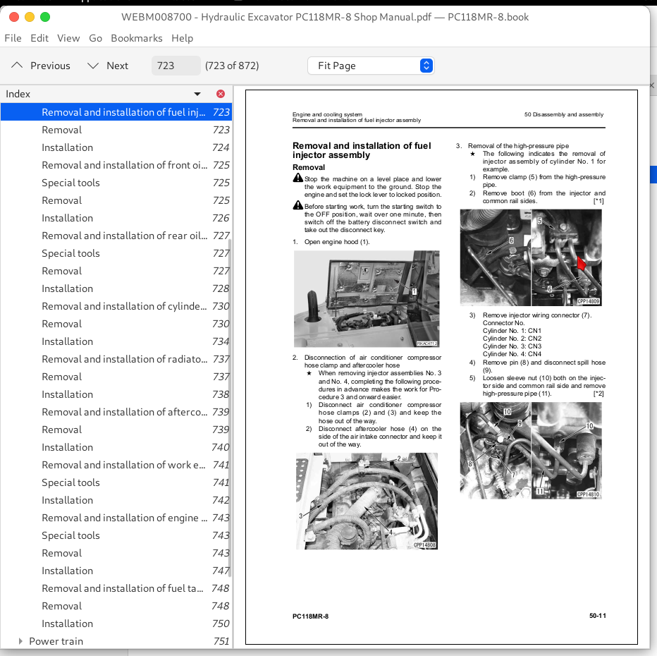
Removal and installation of fuel injector assembly...723
Removal...723
Installation...724
Removal and installation of front oil seal...725
Special tools...725
Removal...725
Installation...726
Removal and installation of rear oil seal...727
Special tools...727
Removal...727
Installation...728
Removal and installation of cylinder head assembly...730
Removal...730
Installation...734
Removal and installation of radiator assembly...737
Removal...737
Installation...738
Removal and installation of aftercooler assembly...739
Removal...739
Installation...740
Removal and installation of work equipment oil cooler assembly...741
Special tools...741
Installation...742
Removal and installation of engine and work equipment pump assembly...743
Special tools...743
Removal...743
Installation...747
Removal and installation of fuel tank assembly...748
Removal...748
Installation...750
Power train...751
Removal and installation of the final drive...751
Removal...751
Installation...751
Removal and installation of swing motor...752
Removal...752
Installation...752
Removal and installation of swing machinery...753
Removal...753
Installation...754
Disassembly and assembly of swing machinery...755
Special tools...755
Disassembly...755
Assembly...758
Removal and installation of swing circle...764
Removal...764
Installation...764
Undercarriage and frame...765
Removal and installation of track roller...765
Removal...765
Installation...765
Disassembly of idler assembly...766
Removal and installation of idler and recoil spring assembly...767
Removal...767
Installation...767
Disassembly of recoil spring...768
Removal and installation of track shoes...769
Removal...769
Installation...769
Removal and installation of sprocket assembly...770
Removal...770
Installation...770
Removal and installation of carrier roller...771
Removal...771
Installation...771
Removal and installation of revolving frame...772
Removal...772
Installation...773
Removal and installation of counterweight assembly...775
Removal...775
Installation...776
Removal and installation of additional counterweight assembly...777
Removal...777
Installation...778
Hydraulic system...779
Removal and installation of center swivel joint assembly...779
Removal...779
Installation...780
Disassembly and assembly of center swivel joint assembly...781
Special tools...781
Disassembly...781
Removal and installation of hydraulic tank assembly...783
Special tools...783
Removal...783
Installation...785
Removal and installation of hydraulic pump assembly...786
Special tools...786
Installation...788
Removal and installation of control valve assembly...789
Special tools...789
Removal...789
Installation...792
Disassembly and assembly control valve...794
Disassembly and assembly of work equipment PPC valve assembly...795
Disassembly...795
Assembly...795
Disassembly and assembly of travel PPC valve assembly...797
Special tools...797
Assembly...797
Removal and installation of boom swing cylinder assembly...799
Removal...799
Installation...800
Removal and installation boom cylinder (version with 2-piece boom)...801
Removal...801
Installation...803
Removal and installation of blade cylinder...804
Removal...804
Installation...804
Disassembly and assembly of hydraulic cylinder assembly...805
Special tools...805
Disassembly...805
Assembly...807
Work equipment...811
Removal and installation work equipment assembly (for 1-piece boom)...811
Removal...811
Installation...813
Removal and installation work equipment assembly (2-piece boom)...814
Removal...814
Installation...815
Removal and installation of boom swing bracket...816
Removal...816
Installation...818
Cab and its attachments...819
Removal and installation of operator cab assembly...819
Removal...819
Installation...823
Removal and installation of operator's cab glass (Stuck glass)...824
Special tools...825
Removal...825
Installation...825
Removal and installation of front window assembly...834
Removal...834
Installation...834
Removal and installation of floor frame assembly...835
Removal...835
Installation...840
Electrical system...841
Removal and installation of air compressor assembly...841
Special tools...841
Removal...841
Installation...842
Removal and installation of air conditioner condenser...843
Removal...843
Installation...844
Removal and installation of air conditioner unit assembly...845
Removal...845
Installation...848
Removal and installation of machine monitor assembly...850
Installation...851
Removal and installation of pump controller assembly...852
Removal...852
Installation...853
Removal and installation of engine controller assembly...855
Removal...855
Installation...855
Removal and installation of KOMTRAX terminal assembly...856
Removal...856
Installation...856
90 Diagrams and drawings...857
Contents...858
Hydraulic diagram...859
Electrical diagram...861
Electrical diagram (1/6)...861
Electrical diagram (2/6)...863
Electrical diagram (3/6)...865
Electrical diagram (4/6)...867
Electrical diagram (5/6)...869
Electrical diagram (6/6)...871
Komatsu Hydraulic Excavator PC118MR Repair Service Manual
![]()