
Komatsu BULLDOZERS D68ESS Repair Service Manual
Complete service repair manual with Electrical Wiring Diagrams for Komatsu BULLDOZERS D68ESS, with all the technical information to maintain, diagnose, repair, and rebuild like professional mechanics.
Komatsu BULLDOZERS D68ESS workshop service repair manual includes:
* Numbered table of contents easy to use so that you can find the information you need fast.
* Detailed sub-steps expand on repair procedure information
* Numbered instructions guide you through every repair procedure step by step.
* Troubleshooting and electrical service procedures are combined with detailed wiring diagrams for ease of use.
* Notes, cautions and warnings throughout each chapter pinpoint critical information.
* Bold figure number help you quickly match illustrations with instructions.
* Detailed illustrations, drawings and photos guide you through every procedure.
* Enlarged inset helps you identify and examine parts in detail.
PRODUCT DETAILS:
Total Pages: 603 pages
File Format: PDF (Internal Links, Bookmarked, Table of Contents, Searchable, Printable, high quality)
Language: English
SEN01128-06 - BULLDOZER D68ESS-12 Shop Manual.pdf
PEN00166-00 - BULLDOZER D68ESS-12 Operation & Maintenance Manual.pdf
MAIN SECTIONS
Cover....1
00 Index and foreword....3
Index....3
Composition of shop manual....4
Table of contents....6
Foreword and general information....13
Safety notice....14
How to read the shop manual....19
Explanation of terms for maintenance standard....21
Handling of connectors newly used for engines....32
How to read electric wire code....35
Precautions when carrying out operation....38
Method of disassembling and connecting push-pull type coupler....41
Standard tightening torque table....44
Conversion table....48
01 Specification....55
Specification and technical data....55
Specification and technical data....56
Specification drawing....56
Specifications....58
Weight table....62
Table of fuel, coolant and lubricants....64
10 Structure, function andmaintenance standard....67
Engine and cooling system....67
Engine and cooling system....68
Radiator, power train, oil cooler....68
Engine control....70
Power train, Part 1....73
Power train, Part 1....74
Power train system....74
Power train skeleton....75
Power train unit....76
Power train hydraulic piping diagram....77
Damper, universal joint....78
Torque converter and PTO....81
Transmission control....86
Transmission....87
Transmission control valve....96
Main relief valve....102
Lubrication relief valve....105
Steering and brake control....106
Power train, Part 2....109
Power train, Part 2....110
Bevel gear shaft, steering clutch and brake....110
Brake valve....120
Scavenging pump strainer....125
Power train oil strainer....126
Power train oil filter....127
Final drive....128
Undercarriage and frame....135
Undercarriage and frame....136
Main frame....136
Suspension....138
Track frame....141
Recoil spring....142
Idler....144
Track roller....145
Carrier roller....146
Track shoe....148
Hydraulic system, Part 1....151
Hydraulic system, Part 1....152
Work equipment hydraulic piping diagram....152
PPC control piping diagram....156
Work equipment control....157
Hydraulic tank and filter....160
Hydraulic pump....162
Power train lubrication pump....163
PPC valve (for steering)....164
PPC charge valve....169
Hydraulic system, Part 2....173
Hydraulic system, Part 2....174
1-spool valve 1....174
CLSS....180
Functions, operation of valve....182
Suction valve....190
3-spool valve 1....192
CLSS....199
Functions, operation of valve....201
Suction valve....210
Work equipment....213
Work equipment....214
Work equipment....214
Cutting edge, end bit....224
Work equipment cylinder....226
Electrical system....229
Electrical system....230
Engine control....230
Machine monitor system....231
Sensors....234
20 Standard value table....239
Standard service value table....239
Standard service value table....240
Standard value table for engine....240
Standard value table for chassis....241
Standard value table for electrical system....246
30 Testing and adjusting....249
Testing and adjusting....249
Testing and adjusting....250
Tools for testing, adjusting, and troubleshooting....250
Measuring blow-by pressure....251
Measuring exhaust color....252
Measuring engine oil pressure....253
Measuring engine speed....254
Testing fan belt tension....255
Measuring speed at torque....256
Adjusting fuel control linkage....257
Adjusting steering/directional lever, gearshift lever, and parking brake lever....259
Adjusting brake pedal linkage....262
Adjusting work equipment lock lever....263
Measuring power train hydraulic pressure....264
Measuring and adjusting work equipment oil pressure....267
Measuring leakage inside cylinder....268
Bleeding air from hydraulic cylinder....268
40 Troubleshooting....271
General information on troubleshooting....271
General information on troubleshooting....272
Points to remember when troubleshooting....272
How to proceed troubleshooting....273
Connector types and mounting locations....275
Connector pin arrangement diagram....276
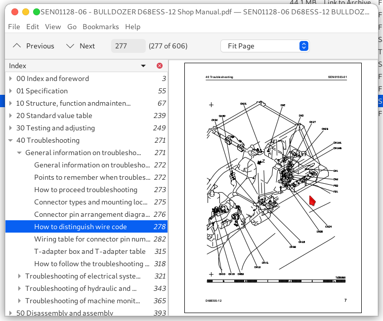
How to distinguish wire code....278
Wiring table for connector pin numbers....282
T-adapter box and T-adapter table....315
How to follow the troubleshooting flow diagrams....318
Troubleshooting of electrical system (E-mode)....321
Troubleshooting of electrical system (E-mode)....322
Table of failure modes and causes (Electrical system)....322
Electrical circuit diagram for each system....324
E-1 Starting motor is not cranked when starting switch is turned to ON....332
E-2 Lamps do not light up....338
Troubleshooting of hydraulic and mechanical system (H-mode)....343
Troubleshooting of hydraulic and mechanical system (H-mode)....346
Table of failure modes and causes (hydraulic, mechanical system)....346
H-1 Brake does not work....348
H-2 Machine does not turn (can travel in a straight line)....349
H-3 Overruns when turning....350
H-4 Can turn in only one direction (when steering lever is operated)....350
H-5 Excessive time lag....351
H-6 Machine can travel in only one direction (forward or reverse)....351
H-7 Machine does not move (when engine is started and lever is shifted to 2nd or 3rd)....352
H-8 Machine does not move in any speed range....354
H-9 Power train oil temperature rises too high....356
H-10 Drawbar pull is weak, travel speed is slow....358
H-11 Abnormal noise is generated from around hydraulic pump....360
H-12 Work equipment speed is slow or lacks power....360
H-13 No work equipment moves....361
H-14 Blade lift or tilt cylinder speed is slow or lacks power....361
H-15 Blade angle cylinder speed is slow or lacks power....362
H-16 Hydraulic drift of blade lift is excessive....362
H-17 Hydraulic drift of blade tilt is excessive....363
H-18 Hydraulic drift of blade angle is excessive....363
Troubleshooting of machine monitor system (M-mode)....365
Troubleshooting of machine monitor system (M-mode)....366
Table of failure modes and causes (machine monitor system)....366
Electrical circuit diagrams for each system....368
M-1 Caution item lights up....376
M-2 Gauge is abnormal....380
M-3 Service meter does not move after engine is started....388
M-4 Monitor panel lighting does not light up (front lamps are normal)....389
50 Disassembly and assembly....393
General information on disassembly and assembly....393
General information on disassembly and assembly....394
How to read this manual....394
Coating materials list....396
Special tool list....399
Sketches of special tools....403
Engine and cooling system....407
Engine and cooling system....408
Removal and installation of engine assembly....408
Removal and installation of....410
Removal and installation of....412
Removal and installation of....415
Removal and installation of fuel tank assembly....416
Removal and installation of....417
Power train....421
Power train....423
Removal and installation of PTO, torque converter and transmission assembly....423
Disconnection and connection of PTO, torque converter and transmission assembly....427
Disassembly and assembly of....429
Disassembly and assembly of....434
Disassembly and assembly of....438
Removal and installation of ....455
Disassembly and assembly of ....456
Removal and installation of transmission control valve assembly....457
Disassembly and assembly of transmission control valve assembly....458
Removal and installation of steering clutch and brake assembly....460
Disassembly and assembly of steering clutch and brake assembly....461
Removal and installation of bevel gear and bevel gear shaft (Clutch and brake model)....468
Removal and installation of brake valve assembly....474
Disassembly and assembly of brake valve assembly....475
Removal and installation of scavenging pump assembly....478
Removal and installation of power train and lubricating oil pump assembly....479
Removal and installation of final drive assembly....481
Disassembly and assembly of final drive assembly....482
Undercarriage and frame....495
Undercarriage and frame....496
Removal and installation of track frame assembly....496
Removal and installation of recoil spring assembly....498
Disassembly and assembly of recoil spring assembly....499
Removal and installation of idler assembly....502
Disassembly and assembly of idler assembly....503
Removal and installation of track roller assembly....507
Disassembly and assembly of track roller assembly....508
Removal and installation of carrier roller assembly....511
Disassembly and assembly of carrier roller assembly....512
Removal and installation of track shoe assembly....514
Overall disassembly and assembly of track shoe assembly....515
Field disassembly and assembly of one link....531
Removal and installation of pivot shaft assembly....538
Removal and installation of equalizer bar assembly....540
Removal and installation of equalizer bar side bushing....542
Removal installation of segment teeth....543
Hydraulic system....545
Hydraulic system....546
Removal and installation of work equipment pump assembly....546
Removal and installation of work equipment control valve assembly....547
Disassembly and assembly of work equipment control valve assembly....549
Removal and installation of steering PPC valve assembly....553
Disassembly and assembly of steering PPC valve assembly....554
Removal and installation of suction valve assembly....557
Removal and installation of blade angle cylinder assembly....558
Removal and installation of blade tilt cylinder assembly....559
Removal and installation of blade lift cylinder assembly....560
Disassembly and assembly of hydraulic cylinder assembly....561
Work equipment....567
Work equipment....568
Removal and installation of work equipment assembly....568
Disassembly and assembly of work equipment assembly....574
Cab and its attachments....579
Cab and its attachments....580
Removal and installation of floor frame assembly....580
Removal and installation of sweep guard....584
Electrical system....587
Electrical system....588
Removal and installation of dashboard assembly....588
Removal and installation of panel assembly....589
90 Diagrams and drawings....591
Hydraulic diagrams and drawings....591
Hydraulic diagrams and drawings....593
Power train hydraulic circuit diagram....593
Work equipment hydraulic circuit diagram (1-spool valve (angle dozer))....594
Work equipment hydraulic circuit diagram (3-spool valve (angle tilt dozer))....595
Work equipment hydraulic circuit diagram (2-spool valve (trimming dozer))....596
Electrical diagrams and drawings....599
Electrical diagrams and drawings....601
Forestry specification, general construction specification....601
Electrical circuit diagram (Serial No. 1003 and up, J10011 and up)....602
Trimming dozer....603
Electrical circuit diagram (2/2)....604
Komatsu BULLDOZERS D68ESS Repair Service Manual
![]()