
John Deere PowerTech 4.5L & 6.8L Diesel Engines Level 11 Electronic Fuel System with Denso HPCR Component Technical Manual (CTM220)
Complete Component Technical Manual for John Deere PowerTech 4.5L & 6.8L Diesel Engines Level 11 Electronic Fuel System with Denso HPCR.
John Deere PowerTech 4.5L & 6.8L Diesel Engines Level 11 Electronic Fuel System with Denso HPCR workshop technical service manual includes:
* Numbered table of contents easy to use so that you can find the information you need fast.
* Detailed sub-steps expand on repair procedure information
* Numbered instructions guide you through every repair procedure step by step.
* Troubleshooting and electrical service procedures are combined with detailed wiring diagrams for ease of use.
* Notes, cautions and warnings throughout each chapter pinpoint critical information.
* Bold figure number help you quickly match illustrations with instructions.
* Detailed illustrations, drawings and photos guide you through every procedure.
* Enlarged inset helps you identify and examine parts in detail.
ctm220 - PowerTechTM 4.5 L and 6.8 L Diesel Engines Level 11 Electronic Fuel System With Denso HPCR (Worldwide Edition) Component Technical Manual.epub
ctm220 - PowerTechTM 4.5 L and 6.8 L Diesel Engines Level 11 Electronic Fuel System With Denso HPCR (Worldwide Edition) Component Technical Manual.pdf
CTM220 (21JAN04) - John Deere PowerTech 4.5L & 6.8L Diesel Engines - John Deere Level 11 Electronic Fuel System with Denso HPCR Technical Manual.pdf
PRODUCT DETAILS:
Total Pages: 675 pages
File Format: PDF/EPUB/MOBI/AZW (PC/Mac/Android/Kindle/iPhone/iPad; bookmarked, ToC, Searchable, Printable)
Language: English
TABLE OF CONTENTS....1
Section 01: General....16
Group 000: Safety....16
Handle Fluids Safely—Avoid Fires....19
Handle Starting Fluid Safely....20
Service Cooling System Safely....21
Prevent Battery Explosions....22
Prepare for Emergencies....23
Handling Batteries Safely....24
Avoid High-Pressure Fluids....27
Avoid Static Electricity Risk When Refueling....28
Wear Protective Clothing....30
Service Machines Safely....31
Work In Ventilated Area....32
Work in Clean Area....33
Remove Paint Before Welding or Heating....34
Avoid Heating Near Pressurized Fluid Lines....35
Illuminate Work Area Safely....36
Use Proper Lifting Equipment....37
Construct Dealer-Made Tools Safely....38
Practice Safe Maintenance....39
Use Proper Tools....41
Decommissioning — Proper Recycling and Disposal of Fluids and Components....42
Live With Safety....43
Group 001: Engine Identification....16
Engine Model Designation....46
Engine Serial Number Plate Information....48
OEM Engine Option Code Label....51
Information Relative to Emissions Regulations....52
Group 002: Fuels, Lubricants, and Coolant....16
Lubricants and Coolant....54
Diesel Fuel....55
Diesel Fuel Additive Products....56
Bio-Diesel Fuel....57
Testing Diesel Fuel....58
Lubricity of Diesel Fuel....59
Section 02: Repair and Adjustments....60
Group 090: Electronic Fuel System Repair and Adjustments....60
Fuel System - General Information....63
Relieve Fuel System Pressure....64
Remove and Install Pre-Filter/Water Bowl Base....65
Replace Pre-Filter Element....67
Remove and Install Final Fuel Filter/Water Bowl Base....69
Replace Final Fuel Filter Element....71
Remove Fuel Transfer Pump....73
Install Fuel Transfer Pump....75
Remove and Install Suction Control Valve....76
Remove and Install High-Pressure Fuel Pump....81
Remove and Install High Pressure Fuel Pump Inlet Filter....85
Remove and Install High Pressure Common Rail....86
Remove and Install Flow Dampers....88
Remove and Install Pressure Limiter....91
Remove Electronic Injectors (EIs)....93
Clean Electronic Injector (EI) Bore....95
Clean Electronic Injector (EI) Orifice....96
Clean Electronic Injector (EI) Body....97
Inspect Electronic Injector (EI) Body....98
Install Electronic Injectors (EIs)....99
Remove and Install Leak-off Lines....102
Clean Electronic injectors (In Engine)....105
Group 110: Electronic Engine Control Repair and Adjustment....60
Engine Control Unit (ECU)....187
Remove and Install Engine Coolant Temperature (ECT) Sensor....109
Remove and Install Fuel Temperature Sensor....110
Remove and Install Manifold Air Temperature (MAT) Sensor....111
Remove and Install Oil Pressure Sensor....112
Remove and Install Fuel Rail Pressure Sensor....113
Remove and Install Crank Position Sensor....115
Remove and Install Pump Position Sensor....116
Remove and Install Glow Plugs....117
Connectors....119
Use Electrical Insulating Compound....120
Using High-Pressure Washer....121
Repair WEATHERPACK Connector....122
Remove Blade Terminals from Connector Body....125
Repair (Pull Type) METRI-PACK Connectors....126
Repair (Push Type) METRI-PACK Connectors....129
Repair DEUTSCH Connectors....132
Repair AMP Connector....135
Repair SUMITOMO™ Connectors....138
Repair YAZAKI™ Connectors....140
Section 03: Theory Of Operation....142
Group 130: Electronic Fuel System Operation....146
About This Group....326
Fuel System Operation....146
Prefilter Operation....148
Fuel Transfer Pump Operation....150
Final Fuel Filter Operation....153
High Pressure Fuel Pump Operation....154
High Pressure Common Rail (HPCR) Operation....155
Electronic Injector (EI) Operation....156
Group 140: Electronic Control System Operation....163
About This Group....326
Electronic Control System Terminology....161
Electronic Control System Operation....163
Electronic Control System Overview....164
Monitoring Engine Parameters....166
Measuring Temperature....168
Measuring Pressure....172
Measuring Throttle Position....177
Measuring Speed....182
Measuring Speed....182
Pump Control Valve (PCV)....184
Water in Fuel (WIF) Sensor....185
Electronic Injector (EI) Wiring Harness Connector....186
Engine Control Unit (ECU)....187
Controlled Area Network (CAN)....189
Pilot Injection Operation....190
Glow Plug Operation....191
Cruise Control Operation....192
Engine Protection....193
Derate Programs....194
Multiple Torque Curve Selection....195
Governor Droop Mode Selection....196
Engine Control Unit (ECU) Self-Diagnosis....197
Section 04: Diagnostics....199
Group 150: Observable Diagnostics and Tests....199
About This Group....326
E1 - Engine Cranks/Won't Start....199
E2 - Engine Misfires/Runs Irregularly....199
E3 - Engine Does Not Develop Full Power....199
E4 - Engine Emits Excessive White Exhaust Smoke....199
E5 - Engine Emits Excessive Black Or Gray Exhaust Smoke....199
E6 - Engine Will Not Crank....199
E7 - Engine Idles Poorly....199
E8 - Abnormal Engine Noise....199
E9 - Analog Throttle (A) Does Not Respond....199
E10 - Analog Throttle (B) Does Not Respond....199
F1 - Fuel Supply System Check....199
F2 - Excessive Fuel Consumption....199
F3 - Fuel in Oil....199
F4 - Excessive Fuel Filter Replacement....251
ECU Does Not Communicate with Service ADVISOR....199
D1 - ECU Does Not Communicate with DST or SERVICE ADVISOR....260
D1 - ECU Does Not Communicate with DST or SERVICE ADVISOR SERVICE ADVISOR is a trademark of Deere & Company....199
D2 - Diagnostic Gauge (Earlier Model) Does Not Communicate With ECU....267
D2 - Diagnostic Gauge (Earlier Model) Does Not Communicate With ECU....267
D3 - Diagnostic Gauge (Later Model) Does Not Communicate With ECU....274
D3 - Diagnostic Gauge (Later Model) Does Not Communicate With ECU....274
A2 - Glow Plug Check....282
A2 - Glow Plug Check....282
A2 - Glow Plug Check....282
Check Fuel Supply Quality....290
Test for Air in Fuel....292
Check Fuel Supply Pressure....294
Check for Restricted Fuel Leak-off Line....296
Bleed the Fuel System....297
Check and Adjust High Pressure Fuel Pump Static Timing....300
Load Profile Information Test — Instructions....301
Primary CAN Diagnostic Procedure....404
Terminal Test....200
Diagnostic Test Box — Using....316
Group 160: Trouble Code Diagnostics and Tests....200
About This Group....326
Electrical Concepts....327
Using a Digital Multimeter....328
Electrical Circuit Malfunctions....329
Troubleshooting Circuit Malfunctions....332
Connecting to Diagnostic Scan Tool (DST)....336
Connecting to Service ADVISOR....340
Blinking DTCs....342
Viewing Active DTCs on Diagnostic Gauge (Earlier Model)....343
Viewing Stored DTCs on Diagnostic Gauge (Earlier Model)....344
Clearing Stored DTCs on Diagnostic Gauge (Earlier Model)....345
Engine Configuration Parameters on Diagnostic Gauge (Earlier Model)....347
Viewing Active DTCs on Diagnostic Gauge (Later Model)....350
Viewing Stored DTCs on Diagnostic Gauge (Later Model)....353
Clearing Stored DTCs on Diagnostic Gauge (Later Model)....355
Data Parameter Description....356
Engine Test Instructions—Cylinder Misfire Test....361
Engine Test Instructions—Compression Test....363
Engine Test Instructions— Cylinder Cutout Test....368
Fuel Rail Cap and Plug Kit....369
Engine Test Instructions— Tractor Torque Curve Change Test....371
Engine Control Unit (ECU) — Level Identification....372
Engine Control Unit (ECU) — Donating this Engine’s ECU to be Used Elsewhere....373
Engine Control Unit (ECU) — Replacing Current ECU with Another ECU....377
Engine Control Unit (ECU) — Replacing Current ECU with Another ECU — Cannot Communicate with Current ECU....379
Engine Control Unit (ECU) — Reprogramming Current ECU....381
Engine Control Unit (ECU) — Reprogramming Instructions....382
Software and Hardware Verification....384
Downloading Payload File For DST....387
Reprogramming Engine Control Unit (ECU) With DST....392
Diagnostic Trouble Codes (DTCs)....396
Listing of Diagnostic Trouble Codes (DTCs) on ECU....397
Diagnostic Procedure....404
Intermittent Fault Diagnostics....405
T1 - Multi-state Throttle Input High....407
T1 - Multi-state Throttle Input High....407
T2 - Multi-state Throttle Input Low....411
T2 - Multi-state Throttle Input Low....411
T3 - Analog Throttle (A) Input High....415
T3 - Analog Throttle (A) Input High....415
T4 - Analog Throttle (A) Input Low....421
T4 - Analog Throttle (A) Input Low....421
T5 - Analog Throttle (B) Input High....427
T5 - Analog Throttle (B) Input High....427
T6 - Analog Throttle (B) Input Low....433
T6 - Analog Throttle (B) Input Low....433
T7 - CAN Throttle Invalid....438
T7 - CAN Throttle Invalid....438
T17 - Analog Throttle (C) Input High....442
T17 - Analog Throttle (C) Input High....442
T18 - Analog Throttle (C) Input Low....446
T18 - Analog Throttle (C) Input Low....446
T22 - Analog Throttle (A) Input Voltage Out of Range....201
000028.03 - Throttle Voltage High....201
000028.04 - Throttle Voltage Low....201
000029.03 - Throttle Voltage High....201
000029.04 - Throttle Voltage Low....201
000084.31 — Vehicle Speed Mismatch....455
000084.31 - Vehicle Speed Mismatch....201
000091.03 - Throttle Voltage High....202
000091.04 - Throttle Voltage Low....202
000091.09 - Throttle Invalid....202
000091.14 - Throttle Voltage Out of Range....202
000094.03 — Fuel Rail Pressure Input Voltage High....464
000094.03 - Fuel Rail Pressure Input Voltage High....202
000094.04 Fuel Rail Pressure Input Voltage Low....469
000094.04 - Fuel Rail Pressure Input Voltage Low....202
000094.10 — Fuel Rail Pressure Loss Detected....474
000094.10 - Fuel Rail Pressure Loss Detected....202
000094.13 — Fuel Rail Pressure Higher Than Expected....478
000094.13 - Fuel Rail Pressure Higher Than Expected....202
000094.17 — Fuel Rail Pressure Not Developed....482
000094.17 - Fuel Rail Pressure Not Developed....202
000097.00 — Water in Fuel Continuously Detected....488
000097.00 - Water in Fuel Continuously Detected....202
000097.03 — Water in Fuel Signal Voltage High....492
000097.03 - Water in Fuel Signal Voltage High....202
000097.04 — Water in Fuel Signal Voltage Low....496
000097.04 - Water in Fuel Signal Voltage Low....202
000097.16 — Water in Fuel Detected....499
000097.16 - Water in Fuel Detected....202
000100.01 — Engine Oil Pressure Extremely Low....503
000100.01 - Engine Oil Pressure Extremely Low....202
000100.03 — Engine Oil Pressure Input Voltage High....507
000100.03 - Engine Oil Pressure Input Voltage High....202
000100.04 — Engine Oil Pressure Input Voltage Low....511
000100.04 - Engine Oil Pressure Input Voltage Low....202
000100.18 — Engine Oil Pressure Moderately Low....517
000100.18 - Engine Oil Pressure Moderately Low....202
000105.00 — Manifold Air Temperature Extremely High....520
000105.00 - Manifold Air Temperature Extremely High....202
000105.03 — Manifold Air Temperature Input Voltage High....523
000105.03 - Manifold Air Temperature Input Voltage High....203
000105.04 — Manifold Air Temperature Input Voltage Low....527
000105.04 - Manifold Air Temperature Input Voltage Low....203
000105.16 — Manifold Air Temperature Moderately High....531
000105.16 - Manifold Air Temperature Moderately High....203
000107.00 — Air Filter Differential Pressure....534
000107.00 - Air Filter Differential Pressure....203
000110.00 — Engine Coolant Temperature Extremely High....537
000110.00 - Engine Coolant Temperature Extremely High....203
000110.03 — Engine Coolant Temperature Input Voltage High....540
000110.03 - Engine Coolant Temperature Input Voltage High....203
000110.04 — Engine Coolant Temperature Input Voltage Low....544
000110.04 - Engine Coolant Temperature Input Voltage Low....203
000110.15 — Engine Coolant Temperature High Least Severe....548
000110.15 - Engine Coolant Temperature High Least Severe....203
000110.16 — Engine Coolant Temperature Moderately High....551
000110.16 - Engine Coolant Temperature Moderately High....203
000111.01 — Engine Coolant Level Low....554
000111.01 - Engine Coolant Level Low....203
000158.17 — ECU Power Down Error....558
000158.17 - ECU Power Down Error....203
000160.02 — Wheel Speed Input Noise....561
000160.02 - Wheel Speed Input Noise....203
000174.00 — Fuel Temperature High Most Severe....566
000174.00 - Fuel Temperature High Most Severe....203
000174.03 — Fuel Temperature Input Voltage High....569
000174.03 - Fuel Temperature Input Voltage High....203
000174.04 — Fuel Temperature Input Voltage Low....573
000174.04 - Fuel Temperature Input Voltage Low....203
000174.16 — Fuel Temperature High Moderately Severe....576
000174.16 - Fuel Temperature High Moderately Severe....203
000189.00 - Engine Speed Derate....203
000190.00 - Engine Overspeed Extreme....203
000190.16 - Engine Overspeed Moderate....204
000237.02 - Vehicle Identification Number Invalid....204
000237.13 - Vehicle Identification Option Code Invalid....204
000237.31 - Vehicle Model Number Invalid....204
000611.03 — Electronic Injector Wiring Shorted To Power Source....585
000611.03 - Electronic Injector Wiring Shorted To Power Source....204
000611.04 — Electronic Injector Wiring Shorted To Ground....591
000611.04 - Electronic Injector Wiring Shorted To Ground....204
000620.03 — Sensor Supply 2 Voltage High....598
000620.03 - Sensor Supply 2 Voltage High....204
000620.04 — Sensor Supply 2 Voltage Low....601
000620.04 - Sensor Supply 2 Voltage Low....204
000627.01 — Electronic Injector Supply Voltage Problem....605
000627.01 - Electronic Injector Supply Voltage Problem....204
000629.13 - ECU Error....204
000636.02 — Pump Position Sensor Input Noise....611
000636.02 - Pump Position Sensor Input Noise....204
000636.08 — Pump Position Sensor Input Missing....615
000636.08 - Pump Position Sensor Input Missing....204
000636.10 — Pump Position Sensor Input Pattern Error....620
000636.10 - Pump Position Sensor Input Pattern Error....204
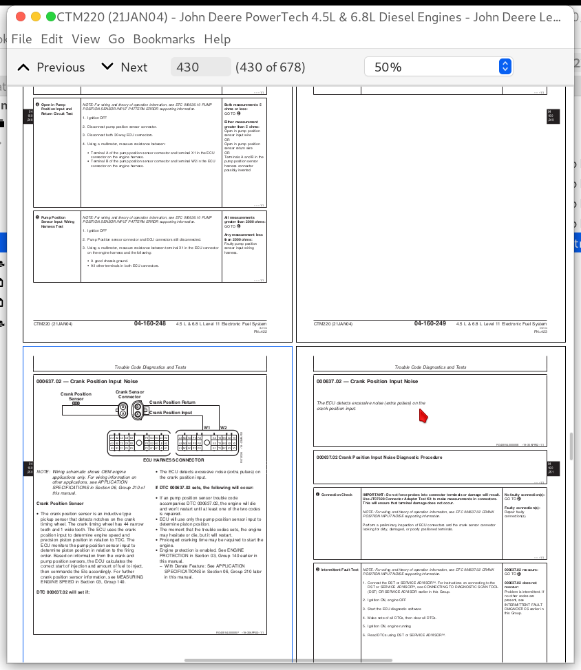
000637.02 — Crank Position Input Noise....625
000637.02 - Crank Position Input Noise....204
000637.07 — Crank Position/Pump Position Timing Moderately Out of Sync....628
000637.07 - Crank Position/Pump Position Timing Moderately Out of Sync....204
000637.08 — Crank Position Input Missing....638
000637.08 - Crank Position Input Missing....204
000637.10 — Crank Position Input Pattern Error....644
000637.10 - Crank Position Input Pattern Error....204
000639.13 — CAN Bus Error....650
000639.13 - CAN Bus Error....204
000651.05 — Cylinder #1 EI Circuit Open....654
000651.05 - Cylinder #1 EI Circuit Open....204
000651.06 — Cylinder #1 EI Circuit Shorted....660
000651.06 - Cylinder #1 EI Circuit Shorted....205
000651.07 — Cylinder #1 EI Mechanical Failure....666
000651.07 - Cylinder #1 EI Mechanical Failure....205
000652.05 — Cylinder #2 EI Circuit Open....672
000652.05 - Cylinder #2 EI Circuit Open....205
000652.06 — Cylinder #2 EI Circuit Shorted....679
000652.06 - Cylinder #2 EI Circuit Shorted....205
000652.07 — Cylinder #2 EI Mechanical Failure....686
000652.07 - Cylinder #2 EI Mechanical Failure....205
000653.05 — Cylinder #3 EI Circuit Open....692
000653.05 - Cylinder #3 EI Circuit Open....205
000653.06 — Cylinder #3 EI Circuit Shorted....699
000653.06 - Cylinder #3 EI Circuit Shorted....205
000653.07 — Cylinder #3 EI Mechanical Failure....706
000653.07 - Cylinder #3 EI Mechanical Failure....205
000654.05 — Cylinder #4 EI Circuit Open....712
000654.05 - Cylinder #4 EI Circuit Open....205
000654.06 — Cylinder #4 EI Circuit Shorted....719
000654.06 - Cylinder #4 EI Circuit Shorted....205
000654.07 — Cylinder #4 EI Mechanical Failure....726
000654.07 - Cylinder #4 EI Mechanical Failure....205
000655.05 — Cylinder #5 EI Circuit Open....732
000655.05 - Cylinder #5 EI Circuit Open....205
000655.06 — Cylinder #5 EI Circuit Shorted....737
000655.06 - Cylinder #5 EI Circuit Shorted....205
000655.07 — Cylinder #5 EI Mechanical Failure....742
000655.07 - Cylinder #5 EI Mechanical Failure....205
000656.05 — Cylinder #6 EI Circuit Open....747
000656.05 - Cylinder #6 EI Circuit Open....205
000656.06 — Cylinder #6 EI Circuit Shorted....752
000656.06 - Cylinder #6 EI Circuit Shorted....205
000656.07 — Cylinder #6 EI Mechanical Failure....757
000656.07 - Cylinder #6 EI Mechanical Failure....206
000676.03 — Glow Plug Relay Voltage High....762
000676.03 - Glow Plug Relay Voltage High....206
000676.05 — Glow Plug Relay Voltage Low....766
000676.05 - Glow Plug Relay Voltage Low....206
000898.09 - Vehicle Speed or Torque Message Invalid....206
000970.31 - Engine Shutdown - Auxiliary Request....206
000971.31 - External Fuel Derate Switch Active....206
001069.09 — Tire Size Invalid....773
001069.09 - Tire Size Invalid....206
001069.31 — Tire Size Error....777
001069.31 - Tire Size Error....206
001079.03 — Sensor Supply 1 Voltage High....780
001079.03 - Sensor Supply 1 Voltage High....206
001079.04 — Sensor Supply 1 Voltage Low....783
001079.04 - Sensor Supply 1 Voltage Low....206
001080.03 — Fuel Rail Pressure Sensor Supply Voltage High....787
001080.03 - Fuel Rail Pressure Sensor Supply Voltage High....206
001080.04 — Fuel Rail Pressure Sensor Supply Voltage Low....790
001080.04 - Fuel Rail Pressure Sensor Supply Voltage Low....206
001109.31 - Engine Protection Shutdown Warning....206
001110.31 - Engine Protection Shutdown....206
001347.03 — Pump Control Valve Current High....796
001347.03 - Pump Control Valve Current High....206
001347.05 — Pump Control Valve Current Mismatch....800
001347.05 - Pump Control Valve Current Mismatch....206
001347.07 — Fuel Rail Pressure Control Error....804
001347.07 - Fuel Rail Pressure Control Error....206
001347.10 — Pump Control Valve Fuel Flow Not Detected....808
001347.10 - Pump Control Valve Fuel Flow Not Detected....206
001568.02 - Torque Curve Selection Invalid....206
001569.31 - Fuel Derate....206
001639.01 — Fan Speed Input Missing....814
001639.01 - Fan Speed Input Missing....207
001639.16 — Fan Speed Higher Than Expected....820
001639.16 - Fan Speed Higher Than Expected....207
001639.18 — Fan Speed Lower Than Expected....824
001639.18 - Fan Speed Lower Than Expected....207
002000.13 - Security Violation....207
002005.09 - ACU Signal Missing....207
002049.09 - CAB Signal Missing....207
002071.09 - CCU Signal Missing....207
Section 05: Tools....833
Group 170: Electronic Fuel/Control System Repair Tools and Other Materials....833
Electronic Fuel System Repair and Adjustment Essential Tools....836
Fuel System Repair and Adjustment Other Materials....838
Electronic Engine Control Repair Tools....839
Control Repair and Adjustment Other Materials....844
Group 180: Diagnostic Service Tools....833
JDE81-4....846
JDG820....847
JDG998....848
JDG10460....849
JDG10461....850
JDG10466....851
JDG10760....852
JDG11233....853
JDG11263....854
JT05412....856
JT07306....857
JT07328....858
Section 06: Specifications....859
Group 200: Repair Specifications....859
Unified Inch Bolt and Cap Screw Torque Values....863
Metric Bolt and Cap Screw Torque Values....865
Electronic Fuel System Repair and Adjustment Specifications....866
Electronic Engine Control Repair and Adjustment Specifications....867
Group 210: Diagnostic Specifications....859
Fuel System Diagnostic Specifications....869
Application Specifications....870
Combines - Sensor Specifications....872
Combines - Torque Curve Selection....874
Combines - Governor Mode Selection....875
Combines - ECU Terminal Identification....876
Loaders - Sensor Specifications....878
Loaders - Torque Curve Selection....880
Loaders - Governor Mode Selection....881
Loaders - ECU Terminal Identification....882
Motor Graders - Sensor Specifications....883
Motor Graders - Torque Curve Selection....885
Motor Graders - Governor Mode Selection....886
Motor Graders - ECU Terminal Identification....887
OEM Engines - Sensor Specifications....889
OEM Engines - Torque Curve Selection....891
OEM Engines - Governor Mode Selection....892
OEM Engines - ECU Terminal Identification....893
OEM Engines - Electronic Control System Wiring Diagram....895
OEM Engines - 4.5L OEM Engines - 4.5L & 6.8L Instrument Panel/Engine Start Components Electrical Wiring Diagram{pgNO}859 6.8L Instrument Panel/Engine Start Components Electrical Wiring Diagram....896
6020 Tractors - Sensor Specifications....897
6020 Tractors - Torque Curve Selection....899
6020 Tractors - Governor Mode Selection....900
6020 Tractors - ECU Terminal Identification....901
Tractors - 7720 - 7820 Series - Sensor Specifications....903
Tractors - 7720 - 7820 Series - Torque Curve Selection....905
Tractors - 7720 - 7820 Series - Governor Mode Selection....906
Tractors - 7720 - 7820 Series - ECU Terminal Identification....907
John Deere PowerTech 4.5L & 6.8L Diesel Engines Level 11 Electronic Fuel System with Denso HPCR Component Technical Manual (CTM220)
![]()