
Volvo L180 series Wheel Loaders Service Manuals

Volvo L180 series Wheel Loaders Service Manuals
Complete official service repair manual with Electrical Wiring Diagrams for L180 Volvo BM, L180 CO Volvo BM, L180 HL Volvo BM, L180C Volvo BM, L180C Volvo, L180C CO Volvo BM, L180C CO Volvo, L180C HL Volvo BM, L180C HL Volvo, L180D Volvo, L180D HL Volvo, L180E Volvo, L180E HL Volvo, L180F Volvo, L180F HL Volvo, L180G Volvo, L180G HL Volvo, L180H Volvo, L180H HL Volvo Wheel Loaders, with all the shop information to maintain, diagnostic, repair, service like professional mechanics.
L180 Volvo BM, L180 CO Volvo BM, L180 HL Volvo BM, L180C Volvo BM, L180C Volvo, L180C CO Volvo BM, L180C CO Volvo, L180C HL Volvo BM, L180C HL Volvo, L180D Volvo, L180D HL Volvo, L180E Volvo, L180E HL Volvo, L180F Volvo, L180F HL Volvo, L180G Volvo, L180G HL Volvo, L180H Volvo, L180H HL Volvo Wheel Loaders workshop service repair manual includes:
* Numbered table of contents easy to use so that you can find the information you need fast.
* Detailed sub-steps expand on repair procedure information
* Numbered instructions guide you through every repair procedure step by step.
* Troubleshooting and electrical service procedures are combined with detailed wiring diagrams for ease of use.
* Notes, cautions and warnings throughout each chapter pinpoint critical information.
* Bold figure number help you quickly match illustrations with instructions.
* Detailed illustrations, drawings and photos guide you through every procedure.
* Enlarged inset helps you identify and examine parts in detail.
TABLE OF CONTENTS
0 - GENERAL
1 - STANDARD PARTS, SERVICE
2 - ENGINE WITH MOUNTING AND EQUIPMENT
3 - ELECTRICAL; WARNING; INFORMATION; INSTRUMENTS
4 - POWER TRANSMISSION
5 - BRAKE
6 - STEERING
7 - FRAME; SPRINGS; DAMPING; AXLE SUSPENSION; WHEEL_TRACK UNIT
8 - MACHINERY HOUSE; CAB; EXTERIOR TRIM PARTS ANYWHERE
9 - HYDRAULIC SYSTEM; DIGGING_HANDLING_GRADING EQUIPMENT; MISCELLANEOUS
PRODUCT DETAILS:
Total Pages: 801
File Format: PDF (bookmarked, Searchable, Printable, high quality)
Language: English
0 - GENERAL
00 - DESCRIPTION; COMPLETE MACHINE
Description
Product Identification Plates L150
Product Identification Plates L180
03 - SPECIFICATIONS
Air conditioning (AC)
Capacities
Volvo BM standard tightening torques
Weights (approx.)
07 - STANDARD TIME
Time Guide
08 - TOOL
E-tools
1 - STANDARD PARTS, SERVICE
17 - SERVICE
Charging batteries
Cleanliness when working on brake and hydraulic systems
Electric welding
Manual release of parking brake
Prosis-Parts-1920x1080-SSD-FullSpeed.mcr
Prosis-Service-1920x1080-SSD-FullSpeed.mcr
Repairing hydraulic system
Towing
19 - GENERAL
A few simple rules for batteries
A few simple rules of safety
A few simple rules when inflating tyres
A few simple rules when servicing
Charging batteries
Danger in connection with polymer materials
Measures to preveent fire
Refrigerant in air-conditioning units
Safety concerns everybody!
Service position
Starting with booster batteries
2 - ENGINE WITH MOUNTING AND EQUIPMENT
21 - ENGINE
Changing crankshaft front oil seal
Checking function, engine
Description
Fitting engine
Oil sump gasket, changing including cleaning oil strainer
Removing engine
Specifications L150
Specifications L180
Starting engine
Starting low-emission engine
22 - LUBRICATING SYSTEM
Specifications L150
Specifications L180
23 - FUEL SYSTEM
Bleeding fuel system
Changing fuel tank
Checking and adjusting idling speed
Checking and adjusting injection timing
Checking stalling speed
Injection system, low-emission engine
Specifications L150
Specifications L180
Speed, checking with frequency meter
25 - INLET & EXHAUST SYSTEM
Intercooler
Specifications L150
Specifications L180
Specifications
26 - COOLING SYSTEM
Specifications L150
Specifications L180
27 - ENGINE CONTROL
Specifications
Stop solenoid, fitting
Stop solenoid
3 - ELECTRICAL; WARNING; INFORMATION; INSTRUMENTS
30 - GENERAL
Description
Electrical distribution box in cab
Specifications
31 - BATTERY
Charging of batteries
Special instructions when working on the electrical system
Specifications
32 - ALTERNATOR; CHARGE REGULATOR
Specifications
33 - STARTING SYSTEM
Specifications
35 - LIGHTING
Headlamps, adjusting
Specifications
36 - OTHER ELECTRICAL EQUIPMENT
Code key for connectors (connected to the circuit board)
Code key for connectors (others)
Monitoring transmission filter
37 - CABLE; FUSE; RELAY
Code key for diodes
Codes using in wiring diagrams
Electrical distribution box
Explanations to wiring diagrams (Lead- and component marking)
List of Cicuits
Wiring diagram, circuit 101 — 108
Wiring diagram, circuit 11 — 110
Wiring diagram, circuit 111 — 117
Wiring diagram, circuit 121 — 129
Wiring diagram, circuit 131 — 1310
Wiring diagram, circuit 141 — 147
Wiring diagram, circuit 151 — 155
Wiring diagram, circuit 161 — 168
Wiring diagram, circuit 171 — 177
Wiring diagram, circuit 181 — 187
Wiring diagram, circuit 191 — 197
Wiring diagram, circuit 201 — 2010
Wiring diagram, circuit 201 — 207
Wiring diagram, circuit 211 — 2110
Wiring diagram, circuit 21 — 210
Wiring diagram, circuit 221 — 229
Wiring diagram, circuit 31 — 310
Wiring diagram, circuit 41 — 410
Wiring diagram, circuit 51 — 510
Wiring diagram, circuit 61 — 610
Wiring diagram, circuit 71 — 79
Wiring diagram, circuit 81 — 810
Wiring diagram, circuit 91 — 97
38 - INSTRUMENT; SENSOR; WARNING & INFORMATION SYSTEM
Contronic Display Unit
Contronic System
Emergency operation, electrical
Functions not included in the central warning
Instruments and controls
Monitored functions
Other electrical functions
Units (functions) connected to the control unit
4 - POWER TRANSMISSION
40 - GENERAL
Description
42 - TRANSMISSION; HYDRAULIC CONTROL
APS (Automatic Power Shift)
Downshifting switch, engine braking
Dual control, gear shifting forward – reverse
Engine power reduction when changing travelling direction
Gear selector valve
Gear shifting, signal to the ECU from the selector control
HT220
Operating with ECU disconnected
Specifications L150
Specifications L180
Tightening torques
Transmission, Checking oil pressure
Transmission, Fault tracing
Transmission
Transmission, Removing and fitting
46 - FRONT AXLE; REAR AXLE
Adjusting differential lock
Differential carrier assembly, AWB40, (L150 w.e.fr. se. no. 1234 and L180)
Differential carrier assembly, Changing L150 w.e.fr. se. no. 1234 and L180 (AWB40)
Differential carrier assembly EV85, L150 up to and incl. se. no. 1233
Fitting rear axle
Hub reduction, Changing seal, One side L150 up to and incl. se. no. 1233 (with drive axles AH65 and 70)
Planetary gear, AH70N, (L150 up to and incl. se. no. 1233)
Planetary gear, AWB40, (L150 w.e.fr. se. no. 1234 up to and incl. 1595 and L180 up to and incl. se. no. 1327)
Planetary gear, AWB40,
Removing rear axle
Specifiactions L180
Specifications L150
Tightening torques
5 - BRAKE
50 - GENERAL
Description
Function
51 - WHEEL BRAKE
Bake discs, Checking wear L150 w.e.fr. ser. no. 1234 (with drive axles AWB40) and L180
Brake discs, Changing L150 up to and incl. ser. no. 1233 (with drive axles AH65 and 70)
Brake discs, Changing L150 w.e.fr. ser. no. 1234 (with drive axles AWB40) and L180
Brake discs, Checking wear L150 up to and incl. ser. no. 1233 (with drive axles AH65 and 70)
Brake piston, Changing seals L150 w.e.fr. ser. no. 1234 (with drive axles AWB40) and L180
52 - HYDRAULIC BRAKE SYSTEM
Accumulator, Checking (Removed)
Bleeding brake system
Brake pedal, Adjusting pedal angle
Brake system, Checking and adjusting pressure in circuit
Brake system, Checking and adjusting, Unloading pressure
Checking function, Brake system
Hydraulic diagram, brake system,
Specifications L150
Specifications L180
55 - PARKING BRAKE
Description
Specifications L150
Specifications L180
Wiring diagram
6 - STEERING
60 - GENERAL
Description
64 - STEERING
Description
Hydraulic diagram, complete
Hydraulic diagram, steering system, basic machine
Hydraulic diagram, steering system, secondary steering
Reconditioning variable piston pump, L150
Reconditioning variable piston pump L180
Shift valve
Shock valves in valve block, checking
Specifications L150
Specifications L180
Steering valve
Tightening torques
Working pressure and stand-by pressure, checking and adjusting
66 - LEVEL STEERING
Description
Hydraulic diagram, steering system, lever steering
Lever steering, adjusting steering speed
Steering lever, checking output voltage
7 - FRAME; SPRINGS; DAMPING; AXLE SUSPENSION; WHEEL_TRACK UNIT
70 - GENERAL
Description
Tightening torques
74 - FRAME LINK
Frame joint, changing bearings and pins
75 - AXLE SUSPENSION
Adjusting axial clearance, rear axle mounting
Changing bushing in axle mounting L150 w.e.fr. se. no. 1234 and L180
Front rear axle bridge, L150 up to and incl. se. no. 1233
Front rear axle bridge, L150 w.e.fr. se. no. 1234 and L180
Measuring axial and radial clearance, rear axle mounting
8 - MACHINERY HOUSE; CAB; EXTERIOR TRIM PARTS ANYWHERE
81 - CAB, NAKED; CANOPY
Tightening torques
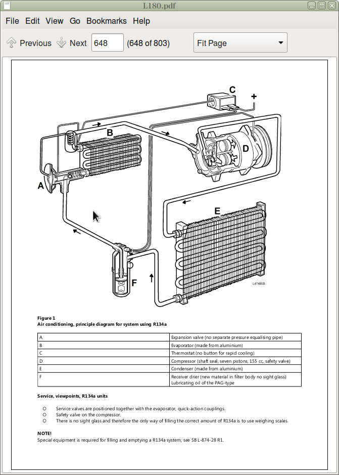
87 - AIR CONDITIONING UNIT
AC safety L150 up to and incl. ser. no. 1328
Air conditioning, performance test (R12 and R134a)
Description
Electrical system
Refrigerants, R134a
Safety valve on receiver drier
9 - HYDRAULIC SYSTEM; DIGGING_HANDLING_GRADING EQUIPMENT; MISCELLANEOUS
91 - WORKING HYDRAULIC; SERVO HYDRAULICS
Attachment unlocking._.locking with Separate attachment locking
Changing or repairing hydraulic pumps
Control valve functions
Description
Hydraulic diagram, L150 basic machine
Hydraulic diagram, L150
Hydraulic diagram, L180 basic machine
Hydraulic diagram, L180
Hydraulic pump
Oil pump, checking and adjusting working pressure
Oil pump, (pump 2) checking and adjusting working pressure
Reconditioning hydraulic oil pump
Separate attachment locking
Servo pressure, checking and adjusting
Servo pressure, checking at spool in control valve
Servo system
Servo valve, adjusting controls
Shock and anti-cavitation functions
Specifications L150
Specifications, L150
Specifications L180
Specifications, L180
94 - UNIT, LOAD HANDLING
Boom kick-out and bucket positioner, adjusting
Boom kick-out, bucket positioner and floating position
Checking and adjusting shock valve, lifting cylinder piston end
Checking and adjusting shock valve, tilting function
Checking opening pressure, back-up valve
Detent function floating position and floating position
Detent function lifting ._. boom kick-out (SW18)
Lifting arm, changing bearings at lower bucket or attachment bracket pivoting points
Lifting cylinder, changing
Lifting cylinder, changing seals in machine
Lifting cylinder
Lifting cylinder (removed), changing bushings
Lifting frame
Tilting cylinder, changing
Tilting cylinder, changing seals in machine
Tilting cylinder
Tilting cylinder (removed), changing bearings
99 - MISCELLANEOUS
Accumulator, boom suspension system
Accumulator, changing seals
Accumulator, checking and adjusting
Boom suspension system, boom suspension system for wheel loaders
Boom suspension system, checking function
Checking closing pressure, pressure-reducing valves R1 and R2
Releasing the hydraulic oil pressure in the accumulators
Safety valve tb, checking opening pressure
Specifications, boom suspension system
Valve block, boom suspension system
![]()