
Cummins QSD 2.8 and 4.2 Liter Diesel Engines Repair Service Manual
Complete service repair manual with Electrical Wiring Diagrams for Cummins QSD 2.8 and 4.2 Liter Diesel Engines, with all the technical information to maintain, diagnose, repair, and rebuild like professional mechanics.
Cummins QSD 2.8 and 4.2 Liter Diesel Engines workshop service repair manual includes:
* Numbered table of contents easy to use so that you can find the information you need fast.
* Detailed sub-steps expand on repair procedure information
* Numbered instructions guide you through every repair procedure step by step.
* Troubleshooting and electrical service procedures are combined with detailed wiring diagrams for ease of use.
* Notes, cautions and warnings throughout each chapter pinpoint critical information.
* Bold figure number help you quickly match illustrations with instructions.
* Detailed illustrations, drawings and photos guide you through every procedure.
* Enlarged inset helps you identify and examine parts in detail.
CMD-4082040 / 90-866941 - Cummins QSD 2.8 and 4.2 Liter Diesel Engines Service Manual.pdf
ECS Diagnostics.pdf
3666070 - Troubleshooting and Repair Manual Cummins CENTRY System.pdf
PRODUCT DETAILS:
Total Pages: 832 pages
File Format: PDF (Internal Links, Bookmarked, Table of Contents, Searchable, Printable, high quality)
Language: English
TABLE OF CONTENTS
3666070 - Troubleshooting and Repair Manual Cummins CENTRY System....1
CMD-4082040 _ 90-866941 - Cummins QSD 2.8 and 4.2 Liter Diesel Engines Service Manual....901
SM47 cover.pdf....901
Page 1....901
FM.pdf....902
Notice To Users Of This Manual....902
Work Precautions....903
Replacement Parts....904
Cleanliness And Care Of Product....904
Manual Outline....906
_1A_english_64_.pdf....908
Section 1A - General Information....908
Table of Contents....908
Introduction....909
How To Use This Manual....909
Engine Serial Number and Decal Locations....909
Engine Dataplate....909
Serial Number Decal....910
Operation—Duty Cycle....910
Duty Cycle Rating....910
High Output Rating....910
Engine Break-In....910
20-Hour Break-In Period....910
After the 20-Hour Break-In Period....911
_1B_english_69_.pdf....912
Section 1B - Maintenance....912
Table of Contents....912
Engine Specifications....914
Tools....916
Approved Paints....916
Capacities....916
Engine....916
QSD 2.8....916
QSD 4.2....917
Sterndrive....917
Bravo Serial Numbers Below 0W240000....917
Bravo Serial Numbers Above 0W240000....917
Transmission....917
Maintenance Intervals....917
Maintenance Schedule—Sterndrive Models....918
Routine Maintenance....918
Scheduled Maintenance....918
Maintenance Schedule—Inboard Models....919
Routine Maintenance....919
Scheduled Maintenance....920
2.8 Engine External Views....921
Starboard Side View ....921
Front View....922
Port Side View....923
Rear View ....924
Top View....925
4.2 Engine External Views....926
Starboard Side View....926
Front View....927
Port Side View....928
Rear View....929
Top View....930
Engine Oil....930
Specifications....930
Oil Level—Overfilled....931
Checking....931
Filling....932
Changing Oil and Filter....933
Sterndrive Gear Lube....935
Checking....935
Filling....936
Changing....937
ZF Marine Transmission Fluid....937
Checking....937
Filling....938
Changing....938
Technodrive Transmission Fluid....940
Checking....940
Filling....942
Changing....942
Power Trim Fluid....945
Checking....945
Filling....945
Changing....946
Power-Assisted Steering Fluid....946
Checking....946
Filling....947
Changing....947
Closed Cooling System....948
Coolant Requirement....948
Checking....948
Draining the Closed Cooling System....949
Cleaning the Closed Cooling System....951
Filling the Closed Cooling System....951
Battery....952
Fuel System....952
General Information....952
Diesel Fuel in Cold Weather....953
Water-Separating Fuel Filter....953
Draining....954
Replacing....954
Filling....957
2.8 Air Filter....958
Removal....958
Inspection....959
Installation....959
4.2 Air Filter....960
Removal....960
Inspection....961
Installation....961
Seawater System....962
Draining the Seawater System....962
Sterndrive Water Inlets Check....964
Checking the Seawater Pickups....965
Cleaning the Seawater Strainer, if Equipped....965
Flushing the Seawater System—Sterndrive Models....966
With the Boat out of the Water....966
With the Boat in the Water....969
Flushing the Seawater System—Inboard Models....970
With the Boat out of the Water....970
With the Boat in the Water....971
Engine Seawater Pump Inspection....973
Corrosion Protection....973
General Information....973
Engine Corrosion Protection Components....973
Removal....973
Cleaning and Inspection....974
Installation....975
Sterndrive Corrosion Protection Components....977
Continuity Circuit—Bravo Sterndrive....979
MerCathode....981
Boat Bottom Care....982
Painting Your Power Package....982
Sterndrive Surface Care....983
Lubrication....984
Steering System....984
Throttle Cable....985
Shift Cable....986
Transom Assembly....987
Propeller Shaft....987
Sterndrive, Bellows, and Engine Alignment....987
Engine Coupler....989
Driveshaft Extension Models....990
Maintaining Torques....990
Gimbal Ring U-bolt Nuts....990
Engine Mounts....991
Electrical System....991
Propellers....991
Bravo Diesel Sterndrive Propeller Removal....991
Bravo One Models....992
Bravo Two Models....993
Bravo Three Models....994
Bravo Diesel Sterndrive Propeller Installation....996
Bravo One Models....996
Bravo Two Models....998
Bravo Three....999
Drive Belts....1000
Serpentine Belt....1001
Inspection....1001
Replacement....1002
Power-Assisted Steering Pump Belt....1003
Inspection....1003
Adjustment....1003
Replacement....1004
Cold Weather (Freezing Temperature), Seasonal Storage, and Extended Storage....1006
Cold Weather (Freezing Temperature) Storage....1007
Preparing Your Power Package for Seasonal or Extended Storage....1007
Seasonal Storage Instructions....1008
Extended Storage Instructions....1009
Battery....1009
Recommissioning....1010
_1C_english_30_.pdf....1012
Section 1C - Troubleshooting....1012
Table of Contents....1012
Troubleshooting Charts....1013
Precautions For Troubleshooting....1013
Poor Boat Performance, Poor Maneuverability, or Both....1014
Improper Full Throttle Engine RPM....1014
RPM Too High....1014
RPM Too Low....1015
Engine Cranks Over But Will Not Start or Starts Hard....1015
Electrical....1015
Fuel System....1015
Miscellaneous....1016
Engine Will Not Crank Over or Starter Inoperative....1016
Charging System Inoperative....1017
Noisy Alternator....1017
Engine Operates Poorly at Idle....1017
Engine Operates Poorly At High RPM....1018
Poor Fuel Economy....1018
Engine Smoking....1019
Black Smoke....1019
Blue Smoke....1019
White Smoke....1019
Exhaust Gas Temperature....1020
High....1020
Low....1020
Turbocharger....1020
Engine Noise....1021
Valve Cover Area Noise....1021
Cylinder Area Noise....1022
Camshaft Area Noise....1022
Crankshaft Area Noise....1022
Miscellaneous Noise....1023
Oil Pressure....1023
Low Oil Pressure....1024
High Oil Pressure....1024
Excessive Oil Consumption....1025
Water or Coolant in the Engine....1025
Water or Coolant In the Engine Oil....1026
Water or Coolant On Top of the Pistons....1026
Engine Overheat—Cooling System....1026
Engine Overheat—Mechanical....1027
Power Steering—Poor, Erratic, or No Assist....1027
Power Steering—Noisy Pump....1028
Power Steering—Fluid Leaks....1028
Seawater Pump—Insufficient Water Flow....1028
ZF Marine Hydraulic Transmission....1029
_2A_english_49_.pdf....1032
Section 2A - Sterndrive Models....1032
Table of Contents....1032
Engine Removal....1033
Engine Installation....1035
Alignment....1038
Exhaust System Connections....1041
Fluid Connections....1042
Seawater Hoses....1042
Power-Assisted Steering Hoses....1043
Hoses With Quick-Connect Fittings....1043
Gear Lube Monitor....1044
Fuel Lines....1045
Throttle and Shift Cable Installation and Adjustment....1046
Throttle Cable Installation and Adjustment....1046
Shift Cable Installation and Adjustment....1048
Electrical Connections....1053
Quick-Connect MerCathode System Connection....1053
Continuity Circuit....1054
Engine to VIP Harness....1054
Neutral Safety Switch Connection....1055
Battery Cable Connection....1056
Sterndrive Installation....1056
_2B_english_59_.pdf....1058
Section 2B - Inboard Models....1058
Table of Contents....1058
Engine Removal....1059
Engine Installation....1061
Centering the Propeller Shaft in the Shaft Log....1062
Aligning the Engine to the Propeller Shaft....1063
Models with ZF Marine 8° Down-Angle Transmission or Technodrive 485-A Transmission....1063
Models with ZF Marine V-drive transmission....1064
Final Engine Alignment....1065
Exhaust System Connections....1071
Fluid Connections....1071
Seawater Hoses....1071
Propeller Shaft Log Seal (Stuffing Box) Connections, If Equipped....1072
Fuel Lines....1073
Electrical Connections....1074
Engine to VIP Harness....1074
Neutral Safety Switch Connection....1074
Battery Cable Connection....1075
Throttle and Shift Cable Installation and Adjustment....1076
Throttle Cable Installation and Adjustment....1076
Shift Cable Installation and Adjustment....1077
_3A_english_46_.pdf....1078
Section 3A - QSD 2.8 and 4.2 Diesel Engines....1078
Table of Contents....1078
Engine Specifications....1081
Camshaft....1081
Cylinder Head....1081
Cylinder Liner Diameter....1081
Cylinder Liner Protrusion....1081
Connecting Rod....1081
Connecting Rod Bushing....1082
Crankshaft....1082
Flywheel....1082
Head Gasket....1082
Oil Pump....1083
Oil Thermostat....1083
Piston....1083
Piston Rings....1083
Rocker Arm....1083
Valve....1084
Valve Clearance....1084
Valve Guide....1084
Valve Lifter....1084
Valve Seat....1084
Valve Spring....1085
General Information....1088
Repair Procedure Information....1088
Engine Rotation....1089
Engine Firing Order....1090
Manual Engine Rotation—2.8....1090
Manual Engine Rotation—4.2....1091
Establishing TDC (Top Dead Center)....1092
Engine Compression Testing....1094
Engine Break-In....1094
20-Hour Break-In Period....1094
After the 20-Hour Break-In Period....1095
Engine Cover....1095
Removal....1095
Cleaning....1095
Inspection....1095
Installation....1095
Valve Cover....1097
Exploded View—2.8L Valve Cover....1097
Exploded View—4.2L Valve Cover....1099
Removal....1101
Cleaning....1103
Inspection....1104
Installation....1104
Oil Separator and Vent System....1107
Exploded View—2.8L Oil Separator and Vent System....1107
Exploded View—4.2L Oil Separator and Vent System....1109
Removal....1111
Cleaning....1112
Inspection....1112
Installation....1113
Coolant Manifold Assembly....1115
Exploded View—2.8 Coolant Manifold Assembly....1115
Exploded View—4.2 Coolant Manifold Assembly....1117
Removal....1119
Cleaning....1121
Inspection....1121
Installation....1122
Cylinder Heads....1125
Exploded View—Cylinder Head....1125
Removal....1129
Disassembly....1130
Cleaning....1131
Inspection....1131
General....1131
Expansion Plugs....1132
Valve Guides....1132
Valve Seats....1133
Valves....1134
Valve Springs....1135
Repair....1137
Expansion Plugs....1137
Valve Guide Replacement....1138
Valve Seat Reconditioning....1138
Valve Reconditioning....1138
Cylinder Head Resurfacing....1139
Assembly....1139
Valves....1139
Cylinder Head Studs....1140
Determining Head Gasket Thickness....1140
Installation....1142
Torque Procedure After the First 20–30 Minutes of Operation....1149
Rocker Arm....1151
Removal....1151
Cleaning....1151
Inspection....1151
Assembly....1152
Installation....1153
2.8 Engine Front Bracket and Timing Gear Cover....1155
Exploded View—2.8 Front Bracket Components....1155
Exploded View—2.8 Timing Gear Cover Components....1157
2.8 Removal....1159
Cleaning....1161
Inspection....1162
Installation....1162
4.2 Engine Front Bracket and Timing Gear Cover....1167
Exploded View—4.2 Front Bracket Components....1167
Exploded View—4.2 Timing Gear Cover Components....1169
Removal....1171
Cleaning....1173
Inspection....1174
Installation....1174
Oil Pump....1178
2.8 Oil Flow Diagrams....1178
4.2 Oil Flow Diagrams....1180
Removal....1181
Cleaning....1182
Inspection....1182
Reassembly....1183
Installation....1184
Idler Gear....1185
Removal....1185
Cleaning....1186
Inspection....1186
Installation....1187
2.8 Oil Pan, Oil Pickup, and Related Components....1189
Exploded View— 2.8 Oil Pan and Related Components....1189
Removal....1191
Oil Dipstick And Tube....1191
Oil Drain Hose....1191
Oil Pan....1192
Oil Pickup....1193
Cleaning....1193
Inspection....1194
Installation....1194
Oil Pickup....1194
Oil Pan....1195
Oil Drain Hose....1196
Oil Dipstick And Tube....1197
4.2 Oil Pan, Oil Pickup, and Related Components....1199
Exploded View—4.2 Oil Pan and Related Components....1199
Removal....1201
Oil Dipstick And Tube....1201
Oil Drain Hose....1201
Oil Pan....1202
Oil Pickup....1203
Cleaning....1203
Inspection....1204
Installation....1204
Oil Pickup....1204
Oil Pan....1204
Oil Drain Hose....1206
Oil Dipstick and Tube....1206
Oil Pressure Relief Valve....1207
Removal....1207
Disassembly....1208
Cleaning....1209
Inspection....1209
Assembly....1209
Installation....1210
Oil Filter and Oil Cooler Assembly....1211
Removal....1211
Disassembly....1212
Cleaning And Inspection....1213
Assembly....1213
Installation....1215
Camshaft....1219
Exploded View—Camshaft ....1219
Testing—Measuring Lobe Lift....1221
Removal....1221
Inspection....1222
General....1222
Camshaft Journal Diameter....1222
Camshaft Height....1222
Clearance Between Thrust Plate and Camshaft....1223
Installation....1223
Camshaft Bearings....1224
Inspection....1224
Removal....1225
Installation....1225
Valve Lifters....1226
Important Information....1226
Removal....1226
Cleaning....1228
Inspection....1228
Installation....1228
Valve Push Rods....1231
Removal....1231
Cleaning....1231
Inspection....1231
Installation....1231
Connecting Rod, Bearings, and Piston Assemblies....1232
Exploded View—Connecting Rod, Bearings, and Piston Assemblies....1232
Checking the Connecting Rod Bearing Clearance—Engine Assembled....1233
Preparation....1233
Connecting Rod Journal Diameter....1233
Connecting Rod Bearing Clearance....1233
Removal....1235
Disassembly....1236
Cleaning....1236
Connecting Rods, Piston Pins and Piston Rings....1236
Connecting Rod Bearings....1236
Pistons....1236
Inspection....1237
Connecting Rod And Piston Pin....1237
Connecting Rod Bearing Clearance - Micrometer Method....1238
Pistons And Rings....1241
Assembly....1243
Installation....1245
Rear Oil Seal....1248
Removal....1248
Installation....1249
Crankshaft and Main Bearings....1251
Exploded View—2.8 Crankshaft and Main Bearings....1251
Exploded View—4.2 Crankshaft and Main Bearings....1253
Removal....1255
Rear Main Bearing Carrier and Bearing....1255
Crankshaft, Main Bearings, and Main Bearing Carriers....1258
Main Bearing Carriers and Bearings....1259
Front Main Bearing....1260
Timing Gear....1260
Cleaning....1261
Crankshaft....1261
Main Bearing Carriers....1261
Main Bearings....1261
Inspection....1261
Crankshaft....1261
Main Bearings....1261
Timing Gear....1264
Flywheel....1264
Installation....1264
Front Main Bearing....1264
Main Bearing Carriers And Main Bearings....1265
Timing Gear....1267
Crankshaft....1268
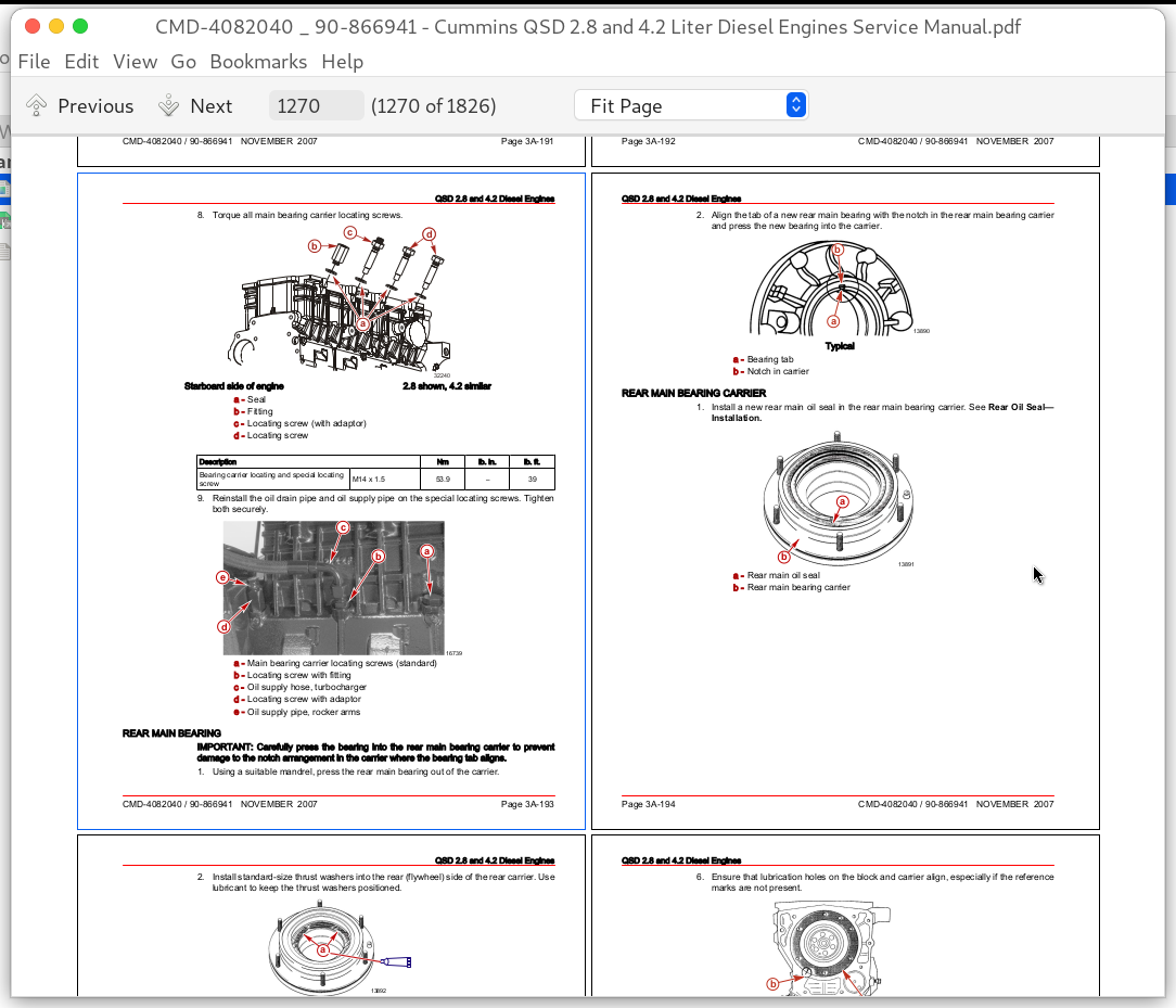
Rear Main Bearing....1270
Rear Main Bearing Carrier....1271
Flywheel Runout....1273
Crankshaft End Play (Axial Clearance)....1273
Piston Cooling Jets (Oil Spray Nozzles)....1275
Exploded View—Piston Cooling Jets (Oil Spray Nozzles)....1275
Removal....1275
Cleaning....1276
Inspection....1276
Installation....1276
Balance Shaft Assembly (2.8 Only)....1277
Removal....1277
Cleaning....1278
Inspection....1278
Installation....1278
Cylinder Liners....1283
Exploded View—Cylinder Liners....1283
Removal....1285
Cleaning and Inspection....1285
Cylinder Liners....1285
Cylinder Block Liner Bores....1286
Installation....1288
Flywheel, Coupler Or Drive Plate, and Flywheel Housing....1293
Exploded View—Sterndrive Flywheel Cover and Coupler....1293
Exploded View—Inboard Flywheel Cover and Drive Plate....1295
Exploded View—Flywheel Housing....1297
Removal....1299
Cleaning....1301
Inspection....1301
Repair....1301
Rear Mounts....1302
Flywheel Ring Gear....1302
Installation....1303
Engine Mounts and Brackets....1307
Exploded View—Engine Mounts and Brackets....1307
Exploded View—V-drive Rear Engine Mounts....1309
Front Mounts....1311
Removal....1311
Cleaning and Inspection....1312
Installation....1312
Sterndrive Models....1314
Inboard Rear Engine Mounts....1314
Removal....1314
Cleaning and Inspection....1314
Installation....1314
V-drive Rear Engine Mounts....1315
Installation Position....1315
Removal....1316
Cleaning and Inspection....1316
Installation....1316
_4A_english_32_.pdf....1318
Section 4A - Starting System....1318
Table of Contents....1318
Starter Specifications....1319
Starter....1319
Wire Color Code Abbreviations....1319
Starting System Components....1320
Starter Inspection....1320
Periodic Inspection....1320
Testing Voltage....1321
Testing Voltage Drop....1321
Starter....1322
Starter Removal....1322
Starter Installation....1323
_4B_english_84_.pdf....1326
Section 4B - Charging System....1326
Table of Contents....1326
Alternator Specifications....1327
Alternator Identification....1327
Wire Color Code Abbreviations....1328
Battery Precautions....1328
Charging a Discharged Battery....1328
Winter Storage of Batteries....1329
Charging System Precautions....1329
Battery Isolators....1330
Alternator Description....1330
Alternator System Components....1332
Periodic Maintenance....1333
Drive Belt Tension Adjustment....1333
Troubleshooting, Alternator On the Engine....1333
Troubleshooting....1333
Preparation....1333
Circuitry Test....1334
Output Circuit....1334
Excitation Circuit....1335
Exploded View, Alternator ....1337
Alternator Removal....1339
Alternator Installation....1340
_4C_english_70_.pdf....1344
Section 4C - Instrumentation....1344
Table of Contents....1344
Tools....1345
Kent-Moore Tools....1345
Wire Color Code Abbreviations....1345
Precautions....1345
General Information....1345
Electrical Overload Protection....1345
Engine Electrical System Overload Protection....1345
Vessel Integration Panel (VIP) Overload Protection....1347
Vessel Interface Panel (VIP)....1347
Removal....1347
Installation....1348
Extension Harness....1349
VesselView....1350
Important Information....1350
Removal....1350
Cleaning....1351
Inspection....1352
Installation....1352
SmartCraft Gauges....1353
Basic Operation....1353
Removal....1355
Cleaning....1356
Inspection....1356
Installation....1357
CAN Bus Testing....1357
System Link Test....1358
SmartCraft Gauge Connections....1358
System Tachometer Harness....1358
System Speedometer Harness....1359
SC1000 System Tachometer and Speedometer Installation (Single Engine)....1360
Dual Engine Installation SC1000 System Tachometer and Speedometer....1361
System Link Gauge Connections....1362
Primary Station Switches....1363
4 Position Key Switch Mounting - With Bezel....1363
4 Position Key Switch Mounting - Without Bezel....1365
Four Position Key Switch Test....1366
Start-Stop Panel Installation....1367
Start-Stop Switch Wiring....1368
Engine and Helm Configuration....1369
Single Engine—Single Helm....1370
Single Engine—Dual Helm....1371
Dual Engine—Single Helm....1373
Dual Engine—Dual Helm....1375
Remote Control Neutral Start Safety Circuit....1377
Primary Station....1377
Secondary Station....1378
Engine Monitoring Features....1379
Audio Warning System....1379
System Tachometer or Speedometer....1379
Senders....1380
_4D_english_58_.pdf....1382
Section 4D - Wiring Diagrams....1382
Table of Contents....1382
Engine Harness Wiring Diagrams....1385
Engine Interface Harness K—Sterndrive Models....1385
Engine Interface Harness K—Inboard Models....1387
2.8 Engine Fuel System Harness A....1388
4.2 Engine Fuel System Harness A....1389
Engine Power Harness....1390
Engine to VIP Wiring Harness....1391
Vessel Interface Panel Wiring Diagram....1392
Vessel Sensor Harness Wiring Diagrams....1393
Sterndrive Vessel Sensor Harness....1393
Inboard Vessel Sensor Harness....1394
Instrumentation Wiring Diagrams....1395
Non-DTS helm harness....1395
SmartCraft System Tachometer....1396
SmartCraft System Tachometer....1397
SmartCraft System Speedometer....1398
VesselView Harness Wiring Diagram....1399
VesselView Harness Diagram....1399
VesselView Harness Pinout Table....1399
MerCathode System....1401
_5A_english_89_.pdf....1402
Section 5A - Component Description....1402
Table of Contents....1402
Introduction....1403
Precautions....1403
Testing Procedure....1404
General Information....1404
Basic Knowledge and Tools Required....1404
Visual and Physical Inspection....1404
Electrostatic Discharge Damage....1404
Diagnostic Information....1404
Terminology....1405
Fuel Flow Diagram....1406
Electronic Control Module (ECM) and Sensors....1406
General Description....1406
Computers and Voltage Signals....1407
Analog Signals....1407
Sensors With More Than Two-wires (MAP / IAT And TP)....1407
Two-Wire Sensors (ECT)....1408
Analog Value Conditioning....1408
Analog value sampling....1408
Analog Value Evaluation....1408
Digital Signals....1409
General....1409
Processing The Digital Inputs....1409
Switch Types....1410
Pulse Counters....1410
Engine Control Module (ECM)....1410
Speed Density System....1411
Speed....1411
Density....1412
ECM Input and Sensor Descriptions....1412
Crankshaft Sensor....1413
Camshaft Position Sensor....1413
Engine Coolant Temperature (ECT) Sensor ....1414
Manifold Absolute Pressure Sensor And Intake Air Temperature Assembly....1414
Intake Air Temperature (IAT) Sensor....1414
Manifold Absolute Pressure (MAP) Sensor....1415
Engine Fuel Temperature (EFT) Sensor....1415
Throttle Position (TP) Sensor....1416
Fuel Management....1416
Modes of Operation....1416
Engine Starting....1416
Engine Operation....1416
Engine Speed Changes....1417
Engine Shut off....1417
Fuel Supply Components....1417
High Pressure Fuel Pump....1417
Fuel Rail (Accumulator)....1417
Rail Fuel Pressure (RFP) Sensor....1417
Electronically Controlled Pressure-control Valve....1418
Sensors....1418
Diagnosis and Testing....1418
ECM Self-Diagnostics....1418
ECM Reactions During Operation....1418
_5B_english_22_.pdf....1420
Section 5B - Fuel Filter Assembly....1420
Table of Contents....1420
Exploded View, Fuel Filter Assembly....1422
Water-Separating Fuel Filter....1423
Draining....1423
Replacing....1424
Filling....1427
Fuel Filter Assembly....1428
Removal....1428
Cleaning and Inspection....1430
Installation....1431
Purging Air From The Fuel System....1433
Water In Fuel (WIF) Warning System....1433
_5C_english_10_.pdf....1436
Section 5C - Common Rail and Fuel Lines....1436
Table of Contents....1436
Common Rail Repair and Service....1437
Exploded View—Common Rail, Fuel Manifold, and Fuel Lines....1438
High Pressure Fuel Lines....1439
Removal....1439
Installation....1441
Common Rail....1447
Removal....1447
Installation....1449
Fuel Manifold....1451
Removal....1451
Cleaning and Inspection....1451
Installation....1452
_5D_english_33_.pdf....1454
Section 5D - Fuel Injectors....1454
Table of Contents....1454
Exploded View—2.8 Fuel Injectors And Related....1457
Exploded View—4.2 Fuel Injectors And Related....1459
Fuel Injector Repair and Service....1461
Fuel Injectors....1461
Description....1461
Removal....1462
Inspection....1464
Installation....1464
ECM Injector Calibration....1466
_5E_english_35_.pdf....1470
Section 5E - High Pressure Fuel Pump....1470
Table of Contents....1470
High Pressure Fuel Pump Identification....1471
Specifications....1471
Fuel Pump Repair and Service....1471
Exploded View—High Pressure Fuel Pump....1473
High Pressure Fuel Pump....1475
Removal....1475
Cleaning and Inspection....1477
Installation....1478
_5F_english_78_.pdf....1482
Section 5F - ECS Diagnostics....1482
Table of Contents....1482
Service Precautions....1484
Service Precautions....1484
Replacement Parts Warning....1485
General Information....1485
Introduction....1485
Service Precautions....1485
ECS and Test Light Compatibility....1486
Basic Knowledge and Tools Required....1486
Visual and Physical Inspection....1486
Electrostatic Discharge Damage....1487
Diagnostic Information....1487
Abbreviations....1487
Diagnostic Information....1488
Abbreviations....1488
ECM Self-Diagnostics....1489
Reading the Codes....1490
Computer Diagnostic System (CDS) Tool....1490
Clearing Codes with the CDS Tool....1490
Diagnosis of Performance Concerns....1491
ECM Input and Sensor Diagram....1491
ECM Connector Pin Layout....1491
Connector Chart....1492
Injection Harness Connector A (60-Pin)....1492
Engine Interface Harness Connector K (94-Pin)....1493
Troubleshooting ECS System....1494
Diagnostic Trouble Code (DTC) Readouts....1494
SmartCraft Display Fault Readouts....1495
Preliminary Checks....1497
Visual and Physical Check....1497
Intermittent Problems....1497
Symptoms....1498
Troubleshooting Charts....1498
Engine Will Not Crank or Cranks Slowly....1498
Engine Cranks but Will Not Start....1498
Engine Hard to Start or Will Not Start....1499
Rough Idle (Irregularly Firing or Engine Shaking)....1500
Engine Operates Rough....1500
Engine Starts, But Will Not Keep Operating.....1501
Surging (Speed Change)....1501
Engine RPM Will Not Reach Rated Speed.....1502
Low Power....1502
Excessive Exhaust Smoke....1503
Engine Will Not Shut Off....1504
Coolant Temperature Above Normal....1504
Coolant Temperature Below Normal....1505
Lubricating Oil Pressure Low....1505
Lubricating Oil Pressure Too High....1506
Lubricating Oil Loss....1507
Compression Knocks....1507
Excessive Vibration....1507
Excessive Engine Noise....1508
Alternator Not Charging or Insufficient Charging....1508
Manifold Air Pressure Sensor....1508
Manifold Air Pressure (MAP) Sensor....1508
Circuit Description....1509
Test Description....1509
Diagnostic Help....1510
Intake Air Temperature Sensor....1510
IAT (Intake Air Temperature) Sensor....1510
Circuit Description....1511
Test Description....1511
Diagnostic Help....1511
Engine Oil Pressure Sensor....1512
Circuit Description....1512
Test Description....1513
Diagnostic Help....1513
Engine Oil Temperature Sensor....1514
Circuit Description....1514
Test Description....1515
Diagnostic Help....1515
Engine Coolant Temperature Sensor....1516
Circuit Description....1516
Test Description....1516
Diagnostic Help....1517
Engine Fuel Temperature Sensor....1517
Circuit Description....1517
Test Description....1518
Diagnostic Help....1518
Rail Fuel Pressure Sensor....1519
Circuit Description....1519
Test Description....1520
Diagnostic Help....1521
Crankshaft Speed Sensor....1521
Circuit Description....1522
Test Description....1522
Diagnostic Help....1522
Fault Code 115....1523
Camshaft Position Sensor....1523
QSD 2.8 and 4.2 Camshaft Position Sensor....1523
QSD 2.0 Camshaft Position Sensor....1523
Circuit Description....1523
Test Description....1524
QSD 2.8 and 4.2....1524
QSD 2.0....1524
Diagnostic Help....1524
Throttle Position Sensor....1525
Circuit Description....1525
Test Description....1526
Diagnostic Help....1527
Atmospheric Pressure Sensor....1528
Circuit Description....1528
Test Description....1528
Diagnostic Help....1528
Water In Fuel Sensor....1528
Circuit Description....1529
Test Description....1529
Diagnostic Help....1529
Fuel Injector Faults....1530
Circuit Description....1530
MR706....1531
MR504 and MR704....1531
Test Description....1531
Diagnostic Help....1532
Fuel Pressure Solenoid....1532
Circuit Description....1533
Test Description....1533
Diagnostic Help....1533
Fuel Rail Pressure Relief Valve....1534
Circuit Description....1534
Diagnostic Help....1534
Battery and Main Relay....1534
Circuit Description....1534
Test Description....1535
Diagnostic Help....1535
Keyswitch Circuit....1536
Circuit Description....1536
Test Description....1536
Diagnostic Help....1536
Alternator Excitation Circuit....1537
Circuit Description....1537
Circuit Diagram....1537
Starter Circuit....1537
Circuit Description....1537
Test Description....1538
Diagnostic Help....1538
ECM Internal Error....1539
Circuit Description....1539
Diagnostic Help....1539
CAN Communication Error....1539
Circuit Description....1539
Diagnostic Help....1539
DTS CAN Communication Error....1540
Circuit Description....1540
Diagnostic Help....1540
ECM Dataset Variant Coding Error....1540
Circuit Description....1540
Diagnostic Help....1541
_6A_english_19_.pdf....1542
Section 6A - Closed-Cooling System....1542
Table of Contents....1542
Closed Cooling System Specifications....1543
Capacity....1543
Thermostat....1543
Pressure Cap....1543
Coolant (Antifreeze)....1543
Precautions....1544
Exploded Views....1547
Exploded View—Cooling System Components....1547
Exploded View—Heat Exchanger and Related Components....1549
Exploded View—Fuel Cooler and Related Components....1551
Exploded View— 2.8 Seawater Pump and Related Components....1553
Exploded View— 4.2 Seawater Pump and Related Components....1555
Cooling System Flow Diagram—Typical....1557
Seawater Section Components....1558
Seawater Pickup Connection....1558
Installation....1559
Seacock....1559
Seawater Strainer....1560
Draining the Seawater System....1560
Cleaning the Seawater Strainer, if Equipped....1563
Seawater Pump—2.8....1564
Removal....1564
Disassembly....1564
Cleaning....1569
Inspection....1569
Assembly....1569
Installation....1574
Seawater Pump—4.2....1575
Removal....1575
Disassembly....1576
Cleaning....1580
Inspection....1580
Assembly....1581
Installation....1585
Testing the Closed-Cooling System....1586
Testing the Closed Cooling System....1586
Testing for Alkalinity....1586
Pressure Testing....1586
Cylinder Head Gasket Leak Testing....1587
Pressure Cap Testing....1588
Draining the Closed Cooling System....1589
Cleaning the Closed Cooling System....1591
Coolant Expansion Tank and Reservoir....1591
Removal....1591
Cleaning And Inspection....1592
Installation....1592
Thermostat....1595
Removal....1595
Cleaning....1596
Inspection....1597
Testing....1597
Installation....1598
Thermostat Housing....1599
Removal....1599
Cleaning and Inspection....1599
Installation....1600
Heat Exchanger and Fluid Cooler Assembly....1601
Removal....1601
Disassembly....1603
Cleaning and Inspection....1606
Assembly....1606
Installation....1610
Fuel Cooler....1613
Inspection Before Removal....1613
Cleaning Without Removal....1613
Removal....1614
Inspection and Cleaning....1614
Installation....1615
Engine Water Circulating Pump....1615
Removal....1615
Cleaning....1616
Inspection....1616
Installation....1617
Filling the Closed Cooling System....1618
_7A_english_61_.pdf....1620
Section 7A - Aftercooler....1620
Table of Contents....1620
Exploded View—2.8 QSD Aftercooler....1621
Exploded View—4.2 QSD Aftercooler....1623
Aftercooler....1624
Removal....1624
Disassembly....1628
Cleaning and Inspection....1630
Assembly....1631
Installation....1634
_7B_english_48_.pdf....1640
Section 7B - Elbows, Risers, Intake and Exhaust Manifold....1640
Table of Contents....1640
Description....1641
Exploded Views....1641
Typical Intake And Exhaust Manifold....1641
Sterndrive Exhaust Systems....1643
Inboard Exhaust Systems....1644
Representative Views Of Complete Inboard Exhaust Systems....1645
Locating And Installing The Sterndrive Exhaust System....1645
Locating And Installing The Inboard Exhaust System....1646
Additional Information....1647
Exhaust Pipe—Sterndrive Models....1648
Removal....1648
Cleaning....1649
Installation....1649
Exhaust Riser or Exhaust Elbow....1650
Removal....1650
Cleaning and Inspection....1653
Installation....1653
Intake And Exhaust Manifold....1656
Removal....1656
Cleaning and Inspection....1658
Installation....1659
_7C_english_63_.pdf....1662
Section 7C - Turbocharger....1662
Table of Contents....1662
Turbocharger Specifications....1663
Turbocharger Identification....1663
Description....1663
Turbocharger....1663
Wastegate....1664
Exploded Views....1665
Exploded View: Turbocharger and Related Components....1665
Exploded View: Boost Pressure Control (Wastegate) Components....1667
Turbocharger....1669
Checking the Turbine Bearings—Assembled....1669
Testing the Turbocharger Boost Pressure....1669
Removal....1670
Cleaning....1672
Inspection....1672
Checking the Axial (End) Play....1672
Measuring the Radial (Side) Play....1672
Installation....1673
Boost Pressure Control....1676
Inspection—Assembled....1676
Removal....1677
Cleaning and Inspection....1678
Installation....1678
Wastegate Valve....1678
Removal....1678
Installation....1680
Wastegate....1681
Removal....1681
Cleaning....1682
Installation....1682
_8A_english_84_.pdf....1684
Section 8A - ZF Marine Transmissions....1684
Table of Contents....1684
Specifications....1685
Operating Specifications....1685
Pressure Specifications....1685
Fluid Specifications....1685
Important Information....1685
Engine....1685
Propeller....1685
Precautions....1686
Transmission And Propeller Rotation....1686
Propeller Rotation on Dual Installations....1687
Transmission Fluid....1687
Checking....1687
Filling....1689
Changing....1689
Removal....1692
Installation....1692
Shift Control And Cables....1695
Transmission Shift Lever and Shift Cable Bracket....1695
Installation and Adjustment....1697
Pressure Test....1700
_8B_english_59_.pdf....1702
Section 8B - Technodrive Transmissions....1702
Table of Contents....1702
Technodrive Transmissions....1703
Precautions....1703
Important Information....1703
Engine....1703
Transmission....1704
Propeller....1704
Technodrive Transmission And Propeller Rotation....1704
Propeller Rotation on Dual Installations....1704
Technodrive Transmission Fluid....1705
Checking....1705
Filling....1706
Changing....1706
Technodrive Transmission Removal....1708
Technodrive Transmission Installation....1710
_8C_english_99_.pdf....1712
Section 8C - Propeller Shaft Models....1712
Table of Contents....1712
Specifications....1713
Checks Made With Boat In the Water....1713
Checks Made With The Boat Out Of The Water And The Propeller Shaft Installed....1715
Checks Made With the Propeller Shaft Removed From the Boat....1717
Strut....1717
_9A_english_46_.pdf....1718
Section 9A - Power-Assisted Steering Pump and Related Components....1718
Table of Contents....1718
Power-Assisted Steering Specifications....1719
Fluid Specifications....1719
Exploded Views....1721
Power-Assisted Steering Pump Assembly....1721
Related Power-Assisted Steering Components....1723
Power-Assisted Steering Pump....1725
Removal....1725
Installation....1728
Hydraulic Hoses....1731
Pressure Hose—Pump to Control Valve....1731
Removal....1732
Installation....1732
Return Hose—Control Valve to Fluid Cooler....1733
Removal....1734
Installation....1734
Fluid Cooler....1735
Fluid Level....1735
Checking....1735
Checking with the Engine Cold....1736
Checking with the Engine Warm....1736
Filling and Bleeding....1737
ECS Diagnostics....1740
Cummins QSD 2.8 and 4.2 Liter Diesel Engines Repair Service Manual
![]()