
Volvo EW180D Excavators Repair Service Manual
Complete service repair manual with Electrical Wiring Diagrams for Volvo EW180D Excavators, with all the technical information to maintain, diagnose, repair, and rebuild like professional mechanics.
Volvo Constructions Wheeled Excavators EW180D workshop service repair manual includes:
* Numbered table of contents easy to use so that you can find the information you need fast.
* Detailed sub-steps expand on repair procedure information
* Numbered instructions guide you through every repair procedure step by step.
* Troubleshooting and electrical service procedures are combined with detailed wiring diagrams for ease of use.
* Notes, cautions and warnings throughout each chapter pinpoint critical information.
* Bold figure number help you quickly match illustrations with instructions.
* Detailed illustrations, drawings and photos guide you through every procedure.
* Enlarged inset helps you identify and examine parts in detail.
PRODUCT DETAILS:
Total Pages: 3,316 pages
File Format: PDF (Internal Links, Bookmarked, Table of Contents, Searchable, Printable, high quality)
Language: English
Volvo EW180D Excavators Service Repair Manual.pdf
TABLE OF CONTENTSS
0 - Foreword................2
0 - GENERAL................3
000 - DESCRIPTION; COMPLETE MACHINE................4
Description; complete machine................5
Component locations ................6
Product plates................10
003 - SPECIFICATIONS................11
Tightening torques................12
Conversion tables................18
Machine weights................26
Capacities................27
Specifications; weight................28
005 - TRANSPOET INSTRUCTION; STORAGE INSTRUCTION; OPERATIONG INSTRUCTION................29
Lifting instructions................30
007 - STANDARD TIME................33
Operation numbers for additional work................34
008 - TOOL................36
E-tool; 3500 Support plate for travel gearbox and motor................37
E-tool; 3502 Plate for turning crankshaft................39
Infrared Thermometer................41
E-3509................43
E-3508................45
009 - MISCELLANEOUS................47
Service positions................48
Welding on the machine................51
Hydraulic cylinders; dieseling................52
Control units; changing................54
1 - STANDARD PARTS; SERVICE................55
16 - LUBRICANT; FUEL; OTHER FLUID................56
Coolant with freezing and corrosion protection................57
Recommended lubricants_{05-27-25}................59
Recommended lubricants_{05-27-01}................63
Coolant................66
Alternative fuels................71
17 - SERVICE................74
Bearings................78
Elimination of trapped hydraulic pressure................79
Replacement parts................81
Service................82
Service methods................83
Pressure testing................84
Hoses and tubes................85
Cleaning prior to repair................86
Tech Tool; operations ................87
Arrival Inspection; according to Inspection Programme................88
Delivery Inspection; according to Inspection Programme................93
Maintenance of Stored Machines; according to Inspection Programme................95
Periodic maintenance................97
Service positions ................98
Maintenance service; daily................101
Maintenance service; every 50 hours................102
Maintenance service; every 250 hours................103
Maintenance service; first 500 hours................104
Maintenance service; every 500 hours................105
Maintenance service; every 1000 hours................107
Maintenance service; every 2000 hours................109
Maintenance service; every 3000 hours_{05-16-36}................111
Maintenance service; every 3000 hours_{05-16-15}................113
Maintenance service; every 4000 hours................115
Maintenance service; every 4500 hours................117
Maintenance service; every 6000 hours_{05-15-01}................118
Boom suspension accumulator; checking and adjusting................119
Tyres; wear and air pressure; checking................123
Checking for cracks and leaks................125
Check engine oil level................126
Test-run and check................127
Lubrication................128
Grease points on dipper arm; lubrication................129
Grease points on booms; lubrication................132
Grease points on undercarriage; lubrication................134
Grease points on superstructure; lubrication................138
Hydraulic system; checking oil level................140
Water separator; drain................142
Coolant level; check................143
Axles; checking oil level................145
Travel gearbox oil level; checking................148
Fuel tank water and sediment; drain................150
Battery condition; check................152
Door hinges; lubricate with grease................155
Cab; prefilter; clean................157
Axles; changing oil................159
Engine; oil and filter; change.................163
Fuel filters; primary and secondary filter; replace................167
Radiator; cleaning................169
Cab; main filter; clean................172
Belts and belt tension; check; replace when needed.................175
Trailer hitch; checking................178
Swing ring gear; grease check................182
Swing gearbox oil level; checking................184
Swing gearbox oil; changing................186
Service journal (included in Operator's manual); fill in................188
Wheel nuts; check torque................189
Brake system; checking function................190
Engine; air cleaner; main filter; replacing.................191
Air conditioning unit; maintenance................194
MATRIS; reading; export reading................195
VCADS Pro; logged errors; read off................197
Travel gearbox; changing oil................199
Brake discs; checking wear................201
Engine; air cleaner; secondary filter; replacing.................204
Cab; prefilter; replace................206
Cab main filter; replacing................208
Fuel tank breather filter; replacing................212
Hydraulic oil return filter; changing_{04-52-31}................214
Hydraulic oil return filter; changing_{04-52-07}................216
Hydraulic tank breather filter; changing................218
Hydraulic oil servo filter; change_{04-51-02}................220
Hydraulic oil servo filter; change_{04-50-34}................224
Hydraulic oil drain filter; change................227
Coolant's freezing point; check................229
Valves; adjusting ................231
Hydraulic system; changing oil................239
Turbocharger inclusive inlet and exhaust systems; leakage; check................243
Coolant; change................247
DPF (Diesel particulate filter); checking and cleaning ................251
Spark plug; replacing ................257
Hydraulic oil suction strainer; cleaning................259
CareTrack backup battery; replacing................262
Measuring condition................265
Cylinder speed................266
Creeping of hydraulic cylinder................269
Swing speed................273
Measuring of swing bearing clearance................274
Coasting left and right swing................275
Travel Speed................277
Emergency operation; description................278
Towing................281
Secondary lowering of digging equipment................284
Starting engine with booster cables................286
19 - GENERAL................288
Safety concerns everybody!................289
Service positions................291
CE marking and declaration of conformity................294
Safety when handling the machine................296
Safety rules when servicing................300
Checklist after a fire or heat exposure................302
Fire prevention measures................303
Health hazards with paint; plastics and rubber................306
Some simple rules regarding tyre handling................308
Safety when using lifting equipment................310
Safety when handling oils and fuel................311
Safety when working with batteries................312
Starting with booster batteries................314
Safety when working with air conditioning refrigerant................315
Safety when working with hydraulic systems................317
Environmental handling for the future................319
Environmentally safe handling................320
Environmentally hazardous fluids................322
Working in environmentally contaminated areas................323
Decontamination................324
Waste handling................325
2 - ENGINE WITH MOUNTING AND EQUIPMENT................326
20 - GENERAL................327
Engine; description................328
Tech Tool; operations................332
Engine; identification................334
Engine; volume................335
Component locations................336
Engine; weights ................339
Electric components location_{04-23-36}................340
Electric components location_{04-23-12}................347
E-ECU MID 128 pre-programmed; replacing................354
E-ECU MID 128 non-programmed; replacing................357
21 - ENGINE................360
Engine; specifications................361
Cylinder compression; PC test................362
Engine characteristic curve................363
Basic check; Engine................365
Troubleshooting................366
Camshaft and flywheel signals; checking with Tech Tool and oscilloscope................368
Engine; removing................374
Engine; installing................384
Engine; weights................395
Engine; tightening torques................396
Crankcase ventilation; description................398
Valve system specifications................399
Valves; adjusting................400
Valve cover; removing................408
Valve cover; installing................413
Crankshaft; description................418
Vibration damper; description................419
Connecting rod; description................421
Oil sump; replacing................423
Oil level sensor; replacing................430
Engine mount front; replacing................434
Engine mounting rear; changing................439
Engine mounting; tightening torque................442
22 - LUBRICATING SYSTEM................445
Lubricating system; description................446
Lubrication system; specifications................450
Lubrication system; tightening torques................452
Lubrication system; component locations................454
Lubrication oil pressure; checking with pressure gauge................456
Oil cooler; replacing................460
Oil cooler; description................464
23 - FUEL SYSTEM................465
Fuel system; description................467
Fuel system; specifications................473
Fuel system; tightening torques................475
Fuel pressure; specifications................481
Instructions for working with electronic fuel injection................483
Fuel pressure; checking................484
Fuel system; component location................487
Fuel feed pump; description................489
Fuel filter; description................490
Feed pump pressure; checking................491
Fuel filter; checking................496
Fuel system; bleeding................497
Feed pump; replacing................499
Fuel filters; replacing................505
Fuel filter extra; replacing................507
Fuel tank; specification................509
Fuel filler pump; specifications................510
Fuel tank; description................511
Fuel tank; replacing................513
Air cleaner; specification ................520
Fuel filler pump; description................521
Fuel filling pump; removing................523
Fuel filling pump; installing................526
Fuel return pressure; checking................528
Injectors; specifications................530
Injectors; replacing................531
High pressure fuel pump; checking................540
Injector sleeves; replacing................545
Fuel rail; replacing................554
Fuel rail pressure; checking................562
Fuel rail pressure sensor; replacing................567
High pressure fuel pump; replacing................569
Fuel control valve (FCV); checking................574
Fuel control valve (FCV); replacing................579
Pressure relief valve (PRV); inspecting................582
Pressure relief valve (PRV); replacing................587
25 - INLET & EXHAUST SYSTEM................590
Inlet and exhaust system; description................592
Inlet and exhaust system; component location................596
Inlet and exhaust system; tightening torques................598
Exhaust pipe flexible tube; replacing................600
Exhaust Aftertreatment System; description_{03-42-38}................603
Exhaust Aftertreatment System; description_{03-42-06}................614
Exhaust Aftertreatment System; component location................625
Regeneration process; description................627
Exhaust aftertreatment system; specifications................632
DPF regeneration control................635
Semi-auto DPF regeneration................636
Perform a service regeneration................637
DPF (Diesel particulate filter); checking and cleaning................639
Exhaust aftertreatment system; tightening torques................645
DPF (Diesel particulate filter) inlet temperature sensor; replacing................647
Spark plug control unit; replacing................650
Glow plug; replacing................652
Fuel metering unit A; replacing................654
Fuel metering unit B; replacing................658
Air pump safety valve; replacing................664
DPF (Diesel particulate filter) outlet temperature sensor; replacing................666
ACM (Aftertreatment control module) non-programmed; replacing................669
ACM (Aftertreatment control module) pre-programmed; replacing................671
Spark plug; inspecting................673
Spark plug cable; replacing................675
Air pump; replacing................677
Burner function; checking................680
Burner; replacing................685
Spark plug; replacing................692
NOx sensor; replacing................694
DOC (Diesel oxidation catalyst); replacing................698
Turbocharger; description................701
Turbocharger; replacing................703
Air cleaner; description................708
Air cleaner; specification................709
Preheating coil; replacing................710
Charge air cooler; replacing................712
26 - COOLING SYSTEM................715
Cooling system; description................716
Cooling system; specifications................719
Carbon dioxide in coolant system; checking................720
Cooling system; tightening torques................726
Cooling system; component location................727
Cooling system pressure; checking................730
Coolant anti-freeze resistance; checking................732
Radiator; description................734
Radiator; replacing................736
Radiator hoses all; replacing................740
Expansion tank; replacing................743
Radiator; removing................746
Radiator; installing................753
Coolant pump; thermostat; specifications................760
Coolant pump; replacing................761
Thermostat; inspecting................768
Thermostat; replacing................771
Cooling fan speed control; description................775
Fan belt and_or alternator-; compressor belt; replacing all belts................777
Cooling fan clutch; description................782
Cooling fan clutch; specifications................785
Cooling fan clutch; replacing................786
27 - ENGINE CONTROL................792
Engine control; specifications................793
Engine speed control switch; specifications................795
Engine speed control switch; description ................796
Engine speed control; function checking................797
29 - MISCELLANEOUS................798
Exhaust gas recirculation (EGR); component location................799
EGR system; tightening torques................801
EGR cooler; replacing................804
EGR temperature sensor; replacing ................817
EGR pressure sensor; replacing ................819
EGR valve; replacing................822
Exhaust Gas Recirculation (EGR); description................823
EGR actuator; replacing................828
EGR venturi tube; replacing................837
EGR system function; checking................840
3 - ELECTRICAL; WARNING; INFORMATION; INSTRUMENTS##................843
30 - GENERAL................844
Electrical system; special instructions for servicing; general................850
Electrical system; special instructions for servicing; electronic components................852
Electrical system; special instructions for servicing; electrical components; batteries................853
Electrical system; special instructions for servicing; electrical components; alternator and charging regulator................855
Electrical system; special instructions for servicing; action when working on machine................856
Electrical system; description................857
Electronic control system; description................858
Communication with data buses................860
Data buses; function................862
Service connection and programming connection................867
Data links; fault tracing with Oscilloscope................869
Electrical system; specifications................879
Tech Tool; operations ................880
Boom Suspension System; description................881
Power Boost control; description................884
Electrical digging brake; description ................886
Emergency operation; description................888
Start lock; description................891
Power OFF................892
Quick fit control; description................893
Boom float position; description ................895
Semi-auto DPF regeneration................897
Limp Home................900
Auto idle device; setting instructions................902
Travel speed control; description................904
Parking brake; description ................907
Control lockout system; description................909
Forward _ Reverse _ Neutral................910
Axle lock................911
Overload warning................914
ECO mode; description................916
VCADS Pro; parameter programming................918
Software parameters; description_{11-55-08}................920
Software parameters; description_{11-54-36}................933
Automatic engine shut-down................946
DPF regeneration control................949
Tiltrotator control system; software updating................974
Troubleshooting strategy................981
Troubleshooting; general................983
Collection of basic data................985
Error code information; general................987
Electrical cables and connectors; checking................989
Troubleshooting tools................994
Special tools for troubleshooting................995
VCADS Pro service tool................997
Tech Tool; operations_................1001
Power supply E-ECU; description and measuring................1003
PPID 437 explanation................1005
Connecting special tools................1006
999 8699 Multi-pin breaker box................1009
999 0014 Adapter cable................1010
999 0025 Adapter cable................1011
999 0062 Extension cable................1012
8883 0028 Adapter cable................1013
88890040 Oscilloscope for VCADS Pro................1014
999 3893 Adapter cable................1015
999 3894 Template................1016
11 666 140 Multimeter................1017
Measuring; general................1018
Measuring symbols; description................1019
Component descriptions................1022
Component troubleshooting; structure; description................1025
Component troubleshooting; checking wiring harness and input_output on ECU................1027
Component troubleshooting; checking component................1029
Component troubleshooting; checking subsystem (circuit)................1031
AL3201; description and measuring................1033
BA3101; description and measuring................1035
CU2501; description and measuring................1037
CU2503; description and measuring................1039
CU9901; description and measuring................1041
FU6; description and measuring................1043
FU18; description and measuring................1044
FU26; description and measuring................1045
FX1005; description and measuring................1046
FX1006; description and measuring................1049
FX1007; description and measuring................1052
FX1008; description and measuring................1055
FX1031; description and measuring................1058
HE2501; description and measuring................1061
MA2301–MA2306; description and measuring................1063
MA2508; description and measuring................1065
MA2509; description and measuring................1067
MA2510; description and measuring................1069
MA2512; description and measuring................1071
MA2602; description and measuring................1073
MA4214; description and measuring................1075
MA4226; description and measuring................1077
MA4227; description and measuring................1079
MA4302; description and measuring................1081
MA4303; description and measuring................1083
MA5205; description and measuring................1085
MA9109; description and measuring................1087
MA9120; description and measuring................1089
MA9121; description and measuring................1091
MA9122; description and measuring................1093
MA9125; description and measuring................1095
MA9152; description and measuring................1097
MA9164; description and measuring................1099
MA9165; description and measuring................1101
MA9615; description and measuring................1103
MA9618; description and measuring................1105
MA9619; description and measuring................1107
MA9620; description and measuring................1109
MID 140 PPID 1144; description and measuring................1111
MO3301; description and measuring................1112
Power supply; ACM (Aftertreatment Control Module); description and measuring................1114
PPID1336; description and measuring................1115
PWM2303; description and measuring................1117
PWM2602; description and measuring................1119
PWM4219; description and measuring................1121
PWM4220; description and measuring................1123
PWM9109; description and measuring................1125
PWM9129; description and measuring................1127
PWM9141; description and measuring................1129
PWM9143; description and measuring................1131
PWM9145; description and measuring................1133
PWM9146; description and measuring................1135
RE2501; description and measuring................1137
RExxxx; Relays general; description and measuring................1139
SAE J1708_1587 Information link; description and measuring................1141
SAE J1939_CAN control link; description and measuring................1144
SAEJ1939_CAN7 Control link; description and measuring................1147
SE2203; description and measuring................1150
SE2301; description and measuring................1152
SE2303; description and measuring................1154
SE2309; description and measuring................1156
SE2512; description and measuring................1158
SE2515; description and measuring................1160
SE2516; description and measuring................1162
SE2519; description and measuring................1164
SE2520; description and measuring................1166
SE2521; description and measuring................1168
SE2522; description and measuring................1170
SE2523; description and measuring................1172
SE2524; description and measuring................1174
SE2525; description and measuring................1176
SE2526; description and measuring................1178
SE2604; description and measuring ................1180
SE2603; description and measuring................1182
SE2604; description and measuring................1184
SE2606; description and measuring................1186
SE2701; description and measuring................1188
SE2703; description and measuring................1190
SE2704; description and measuring................1192
SE4216; description and measuring................1194
SE4217; description and measuring................1196
SE4234; description and measuring................1198
SE4307; description and measuring................1200
SE5201; description and measuring................1202
SE5221; description and measuring................1204
SE8701; description and measuring................1206
SE8702; description and measuring................1208
SE8705; description and measuring................1210
SE8706; description and measuring................1212
SE9105; description and measuring................1214
SE9109; description and measuring................1216
SE9188; description and measuring................1218
SE9401; description and measuring................1220
SID211; description and measuring................1222
SID232; description and measuring................1223
SW2701; description and measuring................1224
SW3301; description and measuring................1226
SW3619; description and measuring................1228
SW4202; description and measuring................1230
SW4205; description and measuring................1232
SW9160; description and measuring................1234
SW9161; description and measuring................1236
SW9162; description and measuring................1238
Error codes; build-up................1240
Error code information; description................1244
Care Track can not communicate with the machine................1246
31 - BATTERY................1248
Battery; storage................1249
Battery; description................1252
Battery; specifications................1254
Battery; charging................1255
Batteries; replacing................1257
32 - ALTERNATOR; CHARGE REGULATOR................1261
Charging; description................1262
Alternator; specifications................1263
Alternator; description................1264
Alternator; replacing incl function checking................1266
Alternator; testing................1270
33 - STARTING SYSTEM................1272
Starter switch (engine start switch); replacing................1273
Starter motor; description................1275
Starter motor; specifications................1276
Starter motor; testing................1277
Starter relay; replacing................1281
Starter motor; tightening torques................1283
Starter motor; replacing................1286
Preheating; description................1291
Preheating; specifications................1292
35 - LIGHTING................1293
Lights; specifications................1294
Headlights; adjusting................1295
Rotating beacon; specifications................1297
Rotating beacon; description................1298
Rotating beacon; replacing................1299
36 - OTHER ELECTRICAL EQUIPMENT................1301
Electric horn; description................1303
Electric horn; specifications................1305
Horn; replacing................1306
Travel alarm; description................1308
Travel alarm; specifications................1311
Travel alarm; replacing................1312
Windscreen wiper; description................1314
Wiper controller; description................1316
Wiper controller; specifications................1318
Windscreen wiper controller; replacing................1319
Upper wiper motor; description................1321
Upper wiper motor; specifications................1323
Windscreen wiper front motor; replacing................1324
Windscreen wiper switch; replacing................1327
Windscreen flusher pump; replacing................1329
Lower wiper motor; description................1331
Lower wiper motor; specifications................1333
Windscreen flusher pump; specifications................1334
Windscreen wiper; components location................1335
Window limit switch; description................1337
Connectors; overview................1339
Switch; replacing................1352
Battery disconnect switch; description................1355
Battery disconnect switch; specifications................1356
Start switch; description................1357
Start switch; specifications................1359
Engine speed control switch; description................1360
Emergency engine speed control switch; description................1361
Emergency engine speed control switch; specifications................1362
Multi-function lever switch; description................1363
Multi-function lever switch; specifications................1365
Control levers; specifications................1366
Manual travel control switch; description................1374
Manual travel control switch; specifications................1375
Auto_Manual pump control switch; description................1376
Auto_Manual pump control switch; specifications................1377
Stabiliser solenoid valve; specifications................1378
Servo valve block solenoids; specifications................1379
Dozer blade solenoid valve; specifications................1380
Electric center passage; specification................1381
Electric center passage; description................1382
Power outlet; specifications................1385
Electric center passage; replacing................1386
Electronic climate control unit ECC; description ................1390
Engine control unit E-ECU; function description................1391
Instrument control unit I-ECU; functional description................1393
Vehicle control unit V-ECU; functional description................1395
Electronic climate control unit ECC; specification ................1396
Instrument control unit I-ECU; specifications................1397
Control units changing; precaution................1398
I-ECU MID 140 non-programmed; replacing................1399
I-ECU MID 140 pre-programmed; replacing................1401
V-ECU MID 187 non-programmed; replacing................1403
V-ECU MID 187 pre-programmed; replacing................1408
37 - CABLE; FUSE; RELAY................1413
Wiring harnesses - Image B................1423
Page 1................1423
Wiring harnesses - Image A................1424
Page 1................1424
Wiring diagram SCH30 - Image_02................1425
Page 1................1425
Wiring diagram SCH30 - Image_01................1426
Page 1................1426
Wiring diagram SCH29 - Image_01................1427
Page 1................1427
Wiring diagram SCH28 - Image_03................1428
Page 1................1428
Wiring diagram SCH28 - Image_01................1429
Page 1................1429
Wiring diagram SCH27 - Image 03................1430
Page 1................1430
Wiring diagram SCH27 - Image 01................1431
Page 1................1431
Wiring diagram SCH25 - Image_03................1432
Page 1................1432
Wiring diagram SCH25 - Image_01................1433
Page 1................1433
Wiring diagram SCH24 - Image_01................1434
Page 1................1434
Wiring diagram SCH23 - Image 03................1435
Page 1................1435
Wiring diagram SCH23 - Image 01................1436
Page 1................1436
Wiring diagram SCH22 - Image_03................1437
Page 1................1437
Wiring diagram SCH22 - Image_01................1438
Page 1................1438
Wiring diagram SCH21 - Image_03................1439
Page 1................1439
Wiring diagram SCH21 - Image_01................1440
Page 1................1440
Wiring diagram SCH20 - Image_03................1441
Page 1................1441
Wiring diagram SCH20 - Image_01................1442
Page 1................1442
Wiring diagram SCH19 - Image_03................1443
Page 1................1443
Wiring diagram SCH19 - Image_01................1444
Page 1................1444
Wiring diagram SCH18 - Image_03................1445
Page 1................1445
Wiring diagram SCH18 - Image_01................1446
Page 1................1446
Wiring diagram SCH17 - Image_03................1447
Page 1................1447
Wiring diagram SCH17 - Image_01................1448
Page 1................1448
Wiring diagram SCH16 - Image_03................1449
Page 1................1449
Wiring diagram SCH16 - Image_01................1450
Page 1................1450
Wiring diagram SCH15 - Image_02................1451
Page 1................1451
Wiring diagram SCH15 - Image_01................1452
Page 1................1452
Wiring diagram SCH14 - Image_03................1453
Page 1................1453
Wiring diagram SCH14 - Image_02................1454
Page 1................1454
Wiring diagram SCH14 - Image 02................1455
Page 1................1455
Wiring diagram SCH14 - Image_01................1456
Page 1................1456
Wiring diagram SCH13 - Image_03................1457
Page 1................1457
Wiring diagram SCH13 - Image_01................1458
Page 1................1458
Wiring diagram SCH12 - Image_03................1459
Page 1................1459
Wiring diagram SCH12 - Image_01................1460
Page 1................1460
Wiring diagram SCH11 - Image_03................1461
Page 1................1461
Wiring diagram SCH11 - Image_01................1462
Page 1................1462
Wiring diagram SCH10 - Image_03................1463
Page 1................1463
Wiring diagram SCH10 - Image_02................1464
Page 1................1464
Wiring diagram SCH10 - Image 02................1465
Page 1................1465
Wiring diagram SCH10 - Image_01................1466
Page 1................1466
Wiring diagram SCH09 - Image_03................1467
Page 1................1467
Wiring diagram SCH09 - Image_01................1468
Page 1................1468
Wiring diagram SCH08 - Image_03................1469
Page 1................1469
Wiring diagram SCH08 - Image_02................1470
Page 1................1470
Wiring diagram SCH08 - Image 02................1471
Page 1................1471
Wiring diagram SCH08 - Image_01................1472
Page 1................1472
Wiring diagram SCH07 - Image_03................1473
Page 1................1473
Wiring diagram SCH07 - Image_01................1474
Page 1................1474
Wiring diagram SCH06 - Image_03................1475
Page 1................1475
Wiring diagram SCH06 - Image_01................1476
Page 1................1476
Wiring diagram SCH05 - Image_03................1477
Page 1................1477
Wiring diagram SCH04 - Image_03................1478
Page 1................1478
Wiring diagram SCH04 - Image_02................1479
Page 1................1479
Wiring diagram SCH04 - Image 02................1480
Page 1................1480
Wiring diagram SCH04 - Image_01................1481
Page 1................1481
Wiring diagram SCH03 - Image_03................1482
Page 1................1482
Wiring diagram SCH03 - Image_01................1483
Page 1................1483
Wiring diagram SCH02 - Image_03................1484
Page 1................1484
Wiring diagram SCH02 - Image_01................1485
Page 1................1485
Wiring diagram SCH01 - Image_03................1486
Page 1................1486
Wiring diagram SCH01 - Image_01................1487
Page 1................1487
Tiltrotator control system; diagram - Image 07................1488
Page 1................1488
Electrical diagram; single acting trailer hydraulic - Image 04................1489
Page 1................1489
Electrical diagram; single acting trailer hydraulic - Image 03................1490
Page 1................1490
Electrical diagram; single acting trailer hydraulic - Image 01................1491
Page 1................1491
Wiring diagram SCH30 - Image 02................1492
Page 1................1492
Wiring diagram SCH30 - Image 01................1493
Page 1................1493
Wiring diagram SCH29 - Image_02................1494
Page 1................1494
Wiring diagram SCH29 - Image 02................1495
Page 1................1495
Wiring diagram SCH29 - Image 01................1496
Page 1................1496
Wiring diagram SCH28 - Image 03................1497
Page 1................1497
Wiring diagram SCH28 - Image_02................1498
Page 1................1498
Wiring diagram SCH28 - Image 02................1499
Page 1................1499
Wiring diagram SCH28 - Image 01................1500
Page 1................1500
Wiring diagram SCH27 - Image 02................1501
Page 1................1501
Wiring diagram SCH25 - Image 03................1502
Page 1................1502
Wiring diagram SCH25 - Image_02................1503
Page 1................1503
Wiring diagram SCH25 - Image 02................1504
Page 1................1504
Wiring diagram SCH25 - Image 01................1505
Page 1................1505
Wiring diagram SCH24 - Image_02................1506
Page 1................1506
Wiring diagram SCH24 - Image 02................1507
Page 1................1507
Wiring diagram SCH24 - Image 01................1508
Page 1................1508
Wiring diagram SCH23 - Image 02................1509
Page 1................1509
Wiring diagram SCH22 - Image 03................1510
Page 1................1510
Wiring diagram SCH22 - Image_02................1511
Page 1................1511
Wiring diagram SCH22 - Image 02................1512
Page 1................1512
Wiring diagram SCH22 - Image 01................1513
Page 1................1513
Wiring diagram SCH21 - Image 03................1514
Page 1................1514
Wiring diagram SCH21 - Image_02................1515
Page 1................1515
Wiring diagram SCH21 - Image 02................1516
Page 1................1516
Wiring diagram SCH21 - Image 01................1517
Page 1................1517
Wiring diagram SCH20 - Image 03................1518
Page 1................1518
Wiring diagram SCH20 - Image_02................1519
Page 1................1519
Wiring diagram SCH20 - Image 02................1520
Page 1................1520
Wiring diagram SCH20 - Image 01................1521
Page 1................1521
Wiring diagram SCH19 - Image 03................1522
Page 1................1522
Wiring diagram SCH19 - Image_02................1523
Page 1................1523
Wiring diagram SCH19 - Image 02................1524
Page 1................1524
Wiring diagram SCH19 - Image 01................1525
Page 1................1525
Wiring diagram SCH18 - Image 03................1526
Page 1................1526
Wiring diagram SCH18 - Image_02................1527
Page 1................1527
Wiring diagram SCH18 - Image 02................1528
Page 1................1528
Wiring diagram SCH18 - Image 01................1529
Page 1................1529
Wiring diagram SCH17 - Image 03................1530
Page 1................1530
Wiring diagram SCH17 - Image_02................1531
Page 1................1531
Wiring diagram SCH17 - Image 02................1532
Page 1................1532
Wiring diagram SCH17 - Image 01................1533
Page 1................1533
Wiring diagram SCH16 - Image 03................1534
Page 1................1534
Wiring diagram SCH16 - Image_02................1535
Page 1................1535
Wiring diagram SCH16 - Image 02................1536
Page 1................1536
Wiring diagram SCH16 - Image 01................1537
Page 1................1537
Wiring diagram SCH15 - Image 03................1538
Page 1................1538
Wiring diagram SCH15 - Image 02................1539
Page 1................1539
Wiring diagram SCH15 - Image 01................1540
Page 1................1540
Wiring diagram SCH14 - Image 01................1541
Page 1................1541
Wiring diagram SCH13 - Image 03................1542
Page 1................1542
Wiring diagram SCH13 - Image_02................1543
Page 1................1543
Wiring diagram SCH13 - Image 02................1544
Page 1................1544
Wiring diagram SCH13 - Image 01................1545
Page 1................1545
Wiring diagram SCH12 - Image 03................1546
Page 1................1546
Wiring diagram SCH12 - Image_02................1547
Page 1................1547
Wiring diagram SCH12 - Image 02................1548
Page 1................1548
Wiring diagram SCH12 - Image 01................1549
Page 1................1549
Wiring diagram SCH11 - Image 03................1550
Page 1................1550
Wiring diagram SCH11 - Image_02................1551
Page 1................1551
Wiring diagram SCH11 - Image 02................1552
Page 1................1552
Wiring diagram SCH11 - Image 01................1553
Page 1................1553
Wiring diagram SCH10 - Image 03................1554
Page 1................1554
Wiring diagram SCH10 - Image 01................1555
Page 1................1555
Wiring diagram SCH09 - Image 03................1556
Page 1................1556
Wiring diagram SCH09 - Image_02................1557
Page 1................1557
Wiring diagram SCH09 - Image 02................1558
Page 1................1558
Wiring diagram SCH09 - Image 01................1559
Page 1................1559
Wiring diagram SCH08 - Image 03................1560
Page 1................1560
Wiring diagram SCH08 - Image 01................1561
Page 1................1561
Wiring diagram SCH07 - Image 03................1562
Page 1................1562
Wiring diagram SCH07 - Image_02................1563
Page 1................1563
Wiring diagram SCH07 - Image 02................1564
Page 1................1564
Wiring diagram SCH07 - Image 01................1565
Page 1................1565
Wiring diagram SCH06 - Image 03................1566
Page 1................1566
Wiring diagram SCH06 - Image_02................1567
Page 1................1567
Wiring diagram SCH06 - Image 02................1568
Page 1................1568
Wiring diagram SCH06 - Image 01................1569
Page 1................1569
Wiring diagram SCH05 - Image 06................1570
Page 1................1570
Wiring diagram SCH05 - Image 03................1571
Page 1................1571
Wiring diagram SCH05 - Image_02................1572
Page 1................1572
Wiring diagram SCH05 - Image_01................1573
Page 1................1573
Wiring diagram SCH05 - Image 01................1574
Page 1................1574
Wiring diagram SCH04 - Image 03................1575
Page 1................1575
Wiring diagram SCH04 - Image 01................1576
Page 1................1576
Wiring diagram SCH03 - Image 03................1577
Page 1................1577
Wiring diagram SCH03 - Image_02................1578
Page 1................1578
Wiring diagram SCH03 - Image 02................1579
Page 1................1579
Wiring diagram SCH03 - Image 01................1580
Page 1................1580
Wiring diagram SCH02 - Image 03................1581
Page 1................1581
Wiring diagram SCH02 - Image_02................1582
Page 1................1582
Wiring diagram SCH02 - Image 02................1583
Page 1................1583
Wiring diagram SCH02 - Image 01................1584
Page 1................1584
Wiring diagram SCH01 - Image 03................1585
Page 1................1585
Wiring diagram SCH01 - Image_02................1586
Page 1................1586
Wiring diagram SCH01 - Image 02................1587
Page 1................1587
Wiring diagram SCH01 - Image 01................1588
Page 1................1588
Tiltrotator control system; diagram - Image 06................1589
Page 1................1589
Tiltrotator control system; diagram - Image 05................1590
Page 1................1590
Tiltrotator control system; diagram - Image 04................1591
Page 1................1591
Tiltrotator control system; diagram - Image 03................1592
Page 1................1592
Tiltrotator control system; diagram - Image 02................1593
Page 1................1593
Tiltrotator control system; diagram - Image 01................1594
Page 1................1594
Electrical diagram; single acting trailer hydraulic - Image 02................1595
Page 1................1595
Wiring diagram; electrical distribution box - Image................1596
Control system diagram - Image................1597
Electrical symbols and designations................1599
Explanation of wiring diagrams................1603
Component designations................1606
Component list Alternator; batteries; capacitors; electronic units; voltage outlet_{004-30-36}................1607
Component list Alternator; batteries; capacitors; electronic units; voltage outlet_{004-30-14}................1609
Component list; fuses_{004-29-41}................1610
Component list; fuses_{004-29-19}................1612
Component list; Heating coils................1614
Component list; lights_{004-28-12}................1615
Component list; lights_{004-27-51}................1617
Component list; Miscellaneous_{004-27-12}................1619
Component list; Miscellaneous_{004-26-50}................1620
Component list; motors................1621
Component list; relays_{004-25-55}................1622
Component list; relays_{004-25-34}................1623
Component list; sensors_{004-24-49}................1624
Component list; sensors_{004-24-28}................1626
Component list; sensors_{004-24-06}................1628
Component list; Solenoid valves_{004-23-27}................1630
Component list; Solenoid valves_{004-23-06}................1632
Component list; Switches_{004-22-32}................1634
Component list; Switches_{004-22-11}................1636
ACM; I_O list................1638
ECC; I_O list................1641
E-ECU; I_O list................1643
I-ECU; I_O list................1647
V-ECU; I_O list................1649
W-ECU; I_O list................1655
Wiring diagram; general_{004-18-18}................1657
Wiring diagram; general_{004-17-57}................1659
Control system diagram_{004-17-23}................1661
Control system diagram_{004-16-59}................1664
Wiring diagram; electrical distribution box................1667
Wiring diagram SCH001_{04-15-52}................1670
Wiring diagram SCH001_{04-15-22}................1676
Wiring diagram SCH002_{04-14-33}................1682
Wiring diagram SCH002_{04-14-03}................1687
Wiring diagram SCH003_{04-13-19}................1692
Wiring diagram SCH003_{04-12-47}................1698
Wiring diagram SCH004_{04-11-55}................1704
Wiring diagram SCH004_{04-11-29}................1711
Wiring diagram SCH005_{04-10-48}................1717
Wiring diagram SCH005_{04-10-18}................1724
Wiring diagram SCH006_{04-09-25}................1729
Wiring diagram SCH006_{04-08-53}................1734
Wiring diagram SCH007_{04-08-11}................1739
Wiring diagram SCH007_{04-07-40}................1744
Wiring diagram SCH008_{04-06-45}................1749
Wiring diagram SCH008_{04-06-01}................1756
Wiring diagram SCH009_{04-05-18}................1763
Wiring diagram SCH009_{04-04-48}................1769
Wiring diagram SCH010_{04-04-03}................1775
Wiring diagram SCH010_{04-03-37}................1782
Wiring diagram SCH011_{04-02-58}................1789
Wiring diagram SCH011_{04-02-29}................1795
Wiring diagram SCH012_{04-01-45}................1801
Wiring diagram SCH012_{04-01-11}................1806
Wiring diagram SCH013_{04-00-28}................1811
Wiring diagram SCH013_{03-59-57}................1817
Wiring diagram SCH014_{03-59-12}................1823
Wiring diagram SCH014_{03-58-45}................1829
Wiring diagram SCH015_{03-58-06}................1833
Wiring diagram SCH015_{03-57-33}................1838
Wiring diagram SCH016_{03-56-39}................1843
Wiring diagram SCH016_{03-56-08}................1850
Wiring diagram SCH017_{03-55-22}................1857
Wiring diagram SCH017_{03-54-52}................1863
Wiring diagram SCH018_{03-54-01}................1869
Wiring diagram SCH018_{03-53-30}................1875
Wiring diagram SCH019_{03-52-45}................1881
Wiring diagram SCH019_{03-52-17}................1887
Wiring diagram SCH020_{03-51-21}................1893
Wiring diagram SCH020_{03-50-52}................1898
Wiring diagram SCH021_{03-50-08}................1903
Wiring diagram SCH021_{03-49-37}................1909
Wiring diagram SCH022_{03-48-59}................1915
Wiring diagram SCH022_{03-48-31}................1920
Wiring diagram SCH023................1925
Wiring diagram SCH024_{03-47-12}................1931
Wiring diagram SCH024_{03-46-47}................1934
Wiring diagram SCH025_{03-46-09}................1937
Wiring diagram SCH025_{03-45-39}................1942
Wiring diagram SCH027................1947
Wiring diagram SCH028_{03-44-17}................1953
Wiring diagram SCH028_{03-43-49}................1958
Wiring diagram SCH029_{03-43-07}................1963
Wiring diagram SCH029_{03-42-41}................1967
Wiring diagram SCH030_{03-42-02}................1971
Wiring diagram SCH030_{03-41-37}................1976
Electrical diagram; single acting trailer hydraulic................1981
Tiltrotator control system; diagram................1986
Wiring harnesses_{003-39-09}................1999
Wiring harnesses_{003-38-42}................2003
Power distribution box; description................2007
Electrical distribution box; description_{003-35-52}................2009
Electrical distribution box; description_{003-35-24}................2012
Electrical distribution box; circuit board replacing................2015
Fuse; description................2018
Relay; description................2020
Relay; specifications................2022
Flasher relay; specifications................2023
Grounding points; frame connections................2024
38 - INSTRUMENT; SENSOR; WARNING & INFORMATION SYSTEM................2027
Instruments and controls; overview................2029
Display unit................2030
Instruments and controls; left instrument panel_{03-29-07}................2031
Instruments and controls; left instrument panel_{03-28-43}................2034
Instruments and controls; right instrument panel_{03-28-07}................2036
Instruments and controls; right instrument panel_{03-27-42}................2039
Instruments and controls; rear instrument panel................2042
Control levers; description................2043
Hour counter; description................2045
Hour counter; specifications................2046
Fuel level sensor; specifications................2047
Swing position sensor; specifications................2049
Control lockout lever switch; description................2050
Control lockout lever switch; specifications................2052
Auto idle pressure switch; specifications................2053
Engine oil pressure sensor; replacing................2054
Engine rotation speed sensor; replacing_{03-21-51}................2057
Engine rotation speed sensor; replacing_{03-21-26}................2059
Engine rotation speed sensor (camshaft); replacing................2062
Hydraulic oil temperature sensor; replacing................2064
Boost pressure _ charge-air temperature sensor; replacing................2067
Temperature sensor cooling system; replacing................2072
NOx sensor; replacing................2074
Oil level sensor; replacing................2075
Fuel rail pressure sensor; replacing................2076
DPF (Diesel particulate filter) inlet temperature sensor; replacing................2077
DPF (Diesel particulate filter) outlet temperature sensor; replacing................2078
EGR temperature sensor; replacing................2079
EGR pressure sensor; replacing................2080
Booting sequence................2081
Main menu................2083
Display unit; content................2085
Setup................2092
Control types for X1 and X3 operation................2100
Pop-up screen................2102
Keypad; description................2104
Keypad; specification................2105
Theft protection................2107
Service mode................2109
Engine system................2111
Hydraulic system................2113
Electrical system................2115
Vehicle information................2119
Language................2121
39 - MISCELLANEOUS................2123
CareTrack system; description................2124
Audio remote controller; specifications................2126
Radio with MP3; specifications................2127
Audio remote controller; description................2128
Radio with MP3; description................2129
DC–DC converter; specifications................2131
DC–DC converter; description................2132
Radio with CD and MP3 player; specifications_{02-58-33}................2134
Radio with CD and MP3 player; specifications_{02-58-12}................2135
Radio with CD and MP3 player; description_{02-57-36}................2137
Radio with CD and MP3 player; description_{02-57-12}................2139
Antenna; replacing................2141
Speaker; replacing................2143
Wireless control unit W-ECU; specification................2145
W-ECU; MID142; changing non-programmed ECU................2146
W-ECU; MID142; changing pre-programmed ECU................2150
CareTrack antenna; replacing................2154
4 - POWER TRANSMISSION................2157
40 - GENERAL................2158
Power transmission; description................2159
Tech Tool; operations ................2160
43 - GEARBOX................2161
Travel gearbox; specifications................2162
Travel gearbox; description................2163
Travel gearbox; bleeding................2173
Travel gearbox; removing................2176
Travel gearbox; installing................2180
Travel gearbox multi-disc; replacing_{02-46-35}................2186
Travel gearbox multi-disc; replacing_{02-45-46}................2208
44 - HYDROSTATIC DRIVE................2211
Swing motor; specifications................2212
Swing motor; description................2213
Swing motor; removing................2217
Swing motor; installing................2221
Swing motor pressure; checking and adjusting................2226
Swing motor; principle of operation................2230
Travel motor; description................2237
Travel motor (electric proportional control); description................2242
Travel motor pressure; checking and adjusting................2250
Travel motor (electric proportional control) pressure; checking and adjusting................2254
Travel motor; calibrating................2258
Travel motor; specifications................2261
Travel motor regulation start; checking and adjusting................2262
Travel motor; removing................2267
Travel motor; installing................2271
Travel motor removed; seal replacing................2275
Retardation valve; replacing................2278
Pump coupling; removing................2283
Pump coupling; installing................2284
Center passage; specifications................2285
Center passage; description................2288
Centre passage; removing................2290
Centre passage; installing................2294
Center passage; disassembling and assembling................2299
45 - PROPELLER SHAFT................2304
Propeller shaft; specifications................2305
Propeller shaft front; replacing................2307
Propeller shaft rear; replacing................2310
46 - FRONT AXLE; REAR AXLE................2313
Front axle; specification................2314
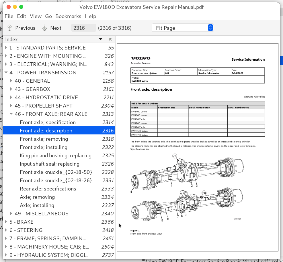
Front axle; description................2316
Front axle; removing................2318
Front axle; installing................2322
King pin and bushing; replacing................2325
Input shaft seal; replacing................2326
Front axle knuckle_{02-18-50}................2328
Front axle knuckle_{02-18-26}................2331
Rear axle; specifications................2333
Axle; removing................2334
Axle; installing................2337
49 - MISCELLANEOUS................2340
Tightening torque; specifications................2341
Swing ring gear; specifications................2342
Swing ring gear; description................2343
Swing ring; removing................2347
Swing ring; installing................2349
Swing ring gear inner seal; replacing................2351
Swing ring gear outer seal; replacing_{02-12-26}................2353
Swing ring gear outer seal; replacing_{02-12-02}................2355
Measuring rotational clearance................2358
Swing ring; measuring axial clearance................2362
5 - BRAKE................2366
52 - HYDRAULIC BRAKE SYSTEM................2367
Electrical digging brake; description................2368
Hydraulic brake system; description................2371
Brake system circuit pressure; checking and adjusting................2376
Brake system; bleeding................2382
Service brakes function; checking................2384
Foot brake valve; replacing................2386
Brake accumulator; specifications................2391
Brake accumulator; description................2393
Discarded accumulators ................2395
Accumulator; removing................2397
Accumulator; installing................2399
Brake accumulator charging pressure; adjusting................2401
Hydraulic oil filter; replacing ................2404
55 - PARKING BRAKE................2406
Parking brake; description................2407
Parking brake; manually releasing................2413
Parking brake function; checking................2416
6 - STEERING................2418
60 - GENERAL................2419
Steering system function; checking................2420
64 - STEERING................2422
Steering system; description_{01-55-47}................2423
Steering system; description_{01-55-16}................2428
Control valve (steering unit); description................2433
Steering system working pressure; checking................2437
Steering valve; removing................2440
Steering valve; installing................2444
Hydraulic oil filter; replacing................2449
7 - FRAME; SPRINGS; DAMPING; AXLE SUSPENSION; WHEEL_TRACK UNIT................2451
71 - FRAME................2452
Superstructure; removing................2453
Superstructure; installing................2458
Counterweight; specifications................2462
Counterweight; removing................2463
Counterweight; installing................2466
Undercarriage; description................2469
Undercarriage; tightening torque................2471
Step; removing................2473
Step; installing................2475
76 - SHOCK ABSORBER; AXLE LOCKING; ANTI ROLL BAR; LEVEL _ SIDE CONTROL................2477
Pivot axle lock cylinder; description................2478
Pivot axle lock cylinder; removing................2485
Pivot axle lock cylinder; installing................2487
Pivot axle lock cylinder; releasing for towing................2489
Pivot axle lock cylinder seals; changing................2491
Pivot axle lock; function check................2496
77 - WHEELS; TRACKS; TYRE; HUB; DRUM................2498
Wheels; specifications................2499
Wheel; removing................2500
Wheel; installing................2502
8 - MACHINERY HOUSE; CAB; EXTERIOR TRIM PARTS ANYWHERE................2504
80 - GENERAL................2505
Tech Tool; operations ................2506
81 - CAB; NAKED; CANOPY................2507
Cab; weight................2508
Cab; removing................2509
Cab; installing................2516
Cab suspension; description................2523
83 - DOORS; HATCH; COVER PLATE; (all)................2524
Cab door; removing door catch................2525
Cab door; installing door catch................2528
84 - TRIM PART; OUTSIDE; GLASS; SEALING MOULDING................2531
Windows; general................2532
Windscreen; replacing................2533
Side window; replacing................2546
Rear window; replacing................2552
Door window; replacing................2557
Cab roof window; replacing................2559
85 - CAB INTERIOR; UPHOLSTERY................2562
Seat heater pad; replacing................2563
Seat; replacing................2570
Seat cushion; replacing................2579
Seat support; replacing................2584
Longitudinal adjustment cable; replacing................2590
Longitudinal suspension cable; replacing................2596
Backrest; replacing................2600
Seat belt; replacing................2604
Driver's seat; description................2607
Driver's seat; specifications................2610
Seat heater; checking................2611
87 - AIR CONDITIONING UNIT................2614
Electronic climate control unit ECC; description................2616
Electronic climate control unit ECC; specification................2617
Wiring diagram................2618
HVAC system................2619
Air conditioning unit; specifications................2621
Air conditioning unit; description................2622
Air-conditioning; component location................2628
Air conditioning unit; maintenance................2630
ECC MID 146 pre-programmed ECU; replacing................2632
ECC MID 146 non-programmed ECU; replacing................2635
Air conditioning unit; refrigerant check and recharging................2639
Air distribution; description................2647
Cab filter; replacing................2649
Heating system; description................2650
Fan motor; replacing................2652
Heater core; replacing................2658
Personal competence and accreditation................2664
Compressor; replacing incl draining and filling................2665
Receiver; replacing incl draining and filling................2669
Condenser; replacing incl draining and filling................2672
Evaporator; replacing incl draining and filling................2675
Expansion valve; replacing incl draining and filling................2680
Vent actuator; replacing................2685
Mode (foot) actuator; replacing................2688
Intake actuator; replacing................2691
Air mix door actuator; replacing................2694
Auxiliary heater; description_{01-04-34}................2697
Auxiliary heater; description_{01-04-09}................2701
Auxiliary heater; principles_{01-03-33}................2706
Auxiliary heater; principles_{01-03-09}................2709
Diesel coolant heater (5kw); specifications................2713
Troubleshooting (5kw)_{01-02-12}................2714
Troubleshooting (5kw)_{01-01-25}................2723
88 - INTERIOR EQUIPMENT................2727
Instrument panel (left); replacing................2728
Instrument panel (right); replacing................2733
9 - HYDRAULIC SYSTEM; DIGGING_HANDLING_GRADING EQUIPMENT; MISCELLANEOUS................2737
90 - GENERAL................2738
Hydraulic diagram; X3 - Image................2740
Page 1................2740
Hydraulic diagram; X1 with pressure control - Image................2741
Page 1................2741
Hydraulic diagram; X1 with flow control - Image................2742
Page 1................2742
Hydraulic diagram; with reversible cooling fan - Image................2743
Page 1................2743
Hydraulic diagram; travel (low speed) - Image................2744
Page 1................2744
Hydraulic diagram; single acting trailer hydraulic - Image 2................2745
Page 1................2745
Hydraulic diagram; single acting trailer hydraulic - Image 1................2746
Page 1................2746
Hydraulic diagram; quick fit - Image 2................2747
Page 1................2747
Hydraulic diagram; quick fit - Image 1................2748
Page 1................2748
Hydraulic diagram; grab piping - Image................2749
Page 1................2749
Hydraulic diagram; dozer blade and outrigger - Image................2750
Page 1................2750
Hydraulic diagram; cruise control - Image................2751
Page 1................2751
Hydraulic diagram; complete - Image................2752
Page 1................2752
Hydraulic diagram; Boom Suspension System - Image................2753
Page 1................2753
Hydraulic diagram; boom float valve - Image................2754
Page 1................2754
Explanations to hydraulic diagram................2755
Hydraulic system; cleanliness when handling hydraulic components................2766
Hydraulic diagram; component list................2768
Hydraulic system; position of main components................2771
Hydraulic diagram; complete................2774
Hydraulic diagram; single acting trailer hydraulic................2777
Hydraulic diagram; with reversible cooling fan................2782
Hydraulic diagram; travel (low speed)................2785
Hydraulic diagram; boom float valve................2788
Hydraulic diagram; Boom Suspension System................2791
Hydraulic diagram; cruise control................2794
Hydraulic diagram; X001 with flow control................2797
Hydraulic diagram; X001 with pressure control................2800
Hydraulic diagram; X003................2803
Hydraulic diagram; quick fit................2806
Hydraulic diagram; grab piping................2811
Hydraulic diagram; dozer blade and outrigger................2814
Description; general................2817
Hydraulic oil; description................2818
Hydraulic system; repair of hydraulic components in workshop................2822
Hydraulic oil; storage and handling................2827
Hydraulic components; storing and transporting................2828
Vacuum pump; connection................2829
Vacuum pump; disconnection................2832
Hydraulic system; warming up................2834
Tech Tool; operations................2838
Measuring tools and techniques................2839
Hydraulic system; flushing................2844
91 - WORKING HYDRAULIC; SERVO HYDRAULICS................2845
Hydraulic system; work instructions................2848
Hydraulic system; description................2849
Hydraulic pressure; specifications................2850
Hydraulic oil; cleaning................2855
Changing the hydraulic oil................2857
Hydraulic oil cooling system; description................2860
Hydraulic oil cooling system; specifications................2861
Hydraulically driven cooling fan; description................2863
Hydraulic tank; specifications................2867
Hydraulic oil tank; description_{12-37-26}................2868
Hydraulic oil tank; description_{12-37-02}................2871
Hydraulic oil tank; releasing pressure................2874
Cooling fan speed; checking and adjusting with VCADS Pro................2875
Hydraulic oil cooler; removing................2880
Hydraulic oil cooler; installing................2881
Hydraulic oil tank; removing................2882
Hydraulic oil tank; installing................2885
Main control valve block; description................2888
Main control valve; removing................2894
Main control valve; installing................2898
Back-up valves................2901
Back-up valve; checking and adjusting................2904
Back-up pressure increase_{12-30-15}................2909
Back-up pressure increase_{12-29-51}................2911
Unload valve; checking and adjusting................2913
Unload valve; replacing................2917
Shock and anti-cavitation valve; description................2921
Line rupture valve (boom); description................2924
Line rupture valve for dipper arm cylinder; description................2927
Line rupture valve for 2-piece boom cylinder X2; description................2932
Line rupture valve (boom); troubleshooting................2937
Line rupture valve pressure; checking and adjusting................2939
Working pressure; checking and adjusting................2945
Secondary pressure limiting valve; checking................2954
Boom cylinder; rupture valve; replacing................2957
Dipper arm cylinder; rupture valve; replacing................2960
Rupture valve; replacing (2pcs boom tilt cylinder)................2963
Dipper arm in speed; checking and adjusting................2967
LS-pressure relief valve; replacing................2969
Pressure relief valves; description................2972
Hydraulic pump; specifications................2976
Working pump; description................2978
Pump; removing................2981
Pump; installing................2985
Servo system; description................2989
Servo valve; removing................2993
Servo valve; installing................2996
Servo pump; removing................2999
Servo pump; installing................3001
Accumulator; description................3003
Servo accumulator; removing................3005
Servo accumulator; installing................3007
Discarded accumulators................3009
Servo pressure; checking and adjusting................3010
Control lockout lever; function check................3013
Servo Accumulator................3015
Remote control valve (pedal); specifications................3016
Control pattern selector valve; description................3018
X1; description................3023
X1; Specifications................3034
Option X1 pressure control................3039
VCADS Pro; 91610-3 – X1 hydraulic pressure control system; test................3047
X1; function check................3050
Calibration of X1 hydraulic with flow control................3052
Calibration of X1 hydraulic with pressure control................3055
X1 Pre-set relief valve; description................3057
X1 pressure relief valve; adjusting................3061
X3; description................3065
X3; specifications................3074
X3; function check................3076
X3 pressure and flow; adjusting................3078
X3 shock and refilling valves; adjusting................3083
Boom float position; description................3087
Cruise control; specifications................3090
Cruise control; description................3091
Reversible cooling fan; description................3096
Grab bucket; description................3100
Tiltrotator control system; description................3106
Boom Suspension System; description_{11-57-13}................3121
Boom Suspension System; description_{11-56-42}................3130
Boom Suspension System; specifications_{11-56-03}................3139
Boom Suspension System; specifications_{11-55-40}................3142
Boom suspension system; component location................3144
Boom suspension accumulator; checking and adjusting................3146
Boom suspension system; changing accumulator................3150
Boom suspension system; solenoid valve test................3154
Trailer towing solution (TTS)................3156
Single acting trailer hydraulic................3164
92 - MECHANICAL EQUIPMENT_ATTACHMENT................3168
Standard quick coupler................3169
Universal quick coupler_{11-50-50}................3174
Universal quick coupler_{11-50-25}................3180
Steelwrist quick coupler_{11-49-49}................3184
Steelwrist quick coupler_{11-49-25}................3191
Hydraulic quickfit cylinder; removing................3192
Hydraulic quickfit cylinder; installing................3196
Cylinder for hydraulic quickfit S1; removing................3199
Cylinder for hydraulic quickfit S1; installing................3201
Cylinder for hydraulic quickfit Universal; removing................3203
Cylinder for hydraulic quickfit Universal; installing................3207
Cylinder for hydraulic quickfit S6; removing................3211
Cylinder for hydraulic quickfit S6; installing................3218
Quickfit; removing................3221
Quickfit; installing................3223
Quickfit; replacing................3226
Quickfit; function check_{11-42-44}................3230
Quickfit; function check_{11-42-20}................3232
Dozer blade; description................3234
97 - UNIT; DIGGING................3235
Cylinder; specifications................3236
Cylinder; description................3237
Boom lifting cylinder; description................3240
Dipper arm cylinder; description................3242
Bucket cylinder; description................3244
Digging equipment bearings; measuring radial clearance................3246
Digging equipment bearings; specifications................3249
Digging equipment bearings; shimming................3251
Stabilisers and stabiliser blade; description................3253
Stabilisers; hydraulic cylinder; removing................3255
Stabilisers; hydraulic cylinder; installing................3259
2-piece boom; removing................3264
2-piece boom; installing................3268
Dipper arm; removing................3272
Dipper arm; installing................3275
Bucket cylinder; removing................3278
Bucket cylinder; installing................3282
99 - MISCELLANEOUS................3286
Automatic lubrication system; specifications................3287
Automatic lubrication system; description................3288
Control unit; description................3295
Control units; software functions................3297
Maintenance service; general................3303
Automatic lubrication pump; removing................3306
Automatic lubrication pump; installing................3308
Troubleshooting................3314
Bleeding air................3316
Volvo EW180D Excavators Repair Service Manual
![]()