
John Deere 5076EN and 5090EN Tractors Diagnosis and Tests Service Technical Manual (TM610019)
Complete Diagnosis & Tests Technical Manual with electrical wiring diagrams for John Deere 5076EN and 5090EN Tractors, with workshop information to maintain, diagnose, and rebuild like professional mechanics.
John Deere 5076EN and 5090EN Tractors workshop Diagnosis & Tests technical manual includes:
* Numbered table of contents easy to use so that you can find the information you need fast.
* Detailed sub-steps expand on repair procedure information
* Numbered instructions guide you through every repair procedure step by step.
* Troubleshooting and electrical service procedures are combined with detailed wiring diagrams for ease of use.
* Notes, cautions and warnings throughout each chapter pinpoint critical information.
* Bold figure number help you quickly match illustrations with instructions.
* Detailed illustrations, drawings and photos guide you through every procedure.
* Enlarged inset helps you identify and examine parts in detail.
tm610019 - 5076EN and 5090EN Tractors Diagnostics Technical Manual.pdf
tm610019 - 5076EN and 5090EN Tractors Diagnostics Technical Manual.epub
PRODUCT DETAILS:
Total Pages: 1,912 pages
File Format: PDF/EPUB/MOBI/AZW (PC/Mac/Android/Kindle/iPhone/iPad; bookmarked, ToC, Searchable, Printable)
Language: English
TABLE OF CONTENTS......1
Section 210: General Information......25
Group 05A: Safety......25
Recognize Safety Information......29
Understand Signal Words......30
Follow Safety Instructions......31
Prepare for Emergencies......32
Wear Protective Clothing......33
Protect Against Noise......34
Handle Fuel Safely—Avoid Fires......35
Handle Starting Fluid Safely......36
Keep ROPS Installed Properly......37
Use Foldable ROPS and Seat Belt Properly......38
Stay Clear of Rotating Drivelines......39
Use Steps and Handholds Correctly......41
Read Operator’s Manuals for ISOBUS Controllers......42
Use Seat Belt Properly......43
Operating the Tractor Safely......44
Limited Use in Forestry Operation......46
Operating the Loader Tractor Safely......47
Keep Riders Off Machine......48
Instructional Seat......49
Use Safety Lights and Devices......50
Use a Safety Chain......51
Transport Towed Equipment at Safe Speeds......52
Use Caution on Slopes, Uneven Terrain, and Rough Ground......54
Freeing a Mired Machine......55
Avoid Contact with Agricultural Chemicals......59
Handle Agricultural Chemicals Safely......57
Avoid Contact with Agricultural Chemicals......59
Handle Fluids Safely—Avoid Fires......61
Install All Guards......62
Use Proper Lifting Equipment......63
Illuminate Work Area Safely......64
Live With Safety......65
Service Machines Safely......66
Use Proper Tools......67
Construct Dealer-Made Tools Safely......68
Clean Vehicle of Hazardous Pesticides......69
Work in Clean Area......70
Decommissioning — Proper Recycling and Disposal of Fluids and Components......71
Avoid Harmful Asbestos Dust......72
Avoid Hot Exhaust......73
Clean Exhaust Filter Safely......74
Handling Batteries Safely......77
Avoid Heating Near Pressurized Fluid Lines......79
Remove Paint Before Welding or Heating......80
Handle Electronic Components and Brackets Safely......81
Practice Safe Maintenance......82
Exhaust Filter Cleaning......84
Work In Ventilated Area......85
Support Machine Properly......86
Prevent Machine Runaway......87
Park Machine Safely......88
Transport Tractor Safely......89
Service Cooling System Safely......90
Service Accumulator Systems Safely......91
Service Tires Safely......92
Service Front-Wheel Drive Tractor Safely......93
Replace Safety Signs......94
Tightening Wheel Retaining Bolts/Nuts......95
Avoid High-Pressure Fluids......96
Avoid Backover Accidents......97
Do Not Open High-Pressure Fuel System......98
Store Attachments Safely......99
Group 05B: General References......26
Reference Publications......101
General Information - Summary of References......102
Regions and Country Versions......103
How to Use This Manual......105
Information Available in Sections, Groups and Subgroups......106
General Troubleshooting Information......107
Systematic Diagnostic Approach Overview......109
Glossary of Terms......113
Trademarks......117
Group 05C: Technical Specific References......27
Features and Accessories......121
Metric Bolt and Screw Torque Values......124
Unified Inch Bolt and Screw Torque Values......126
Section 211: Diagnostic Trouble Codes......128
Group CCU: CCU Code Diagnostics......128
CCU 000000.00-999999.99 - CCU Diagnostic Trouble Codes......128
Group HCU: HCU Code Diagnostics......128
HCU 000000.00-999999.99 - HCU Diagnostic Trouble Codes......128
Group ICC: ICC Code Diagnostics......128
ICC 000000.00-999999.99 - ICC Diagnostic Trouble Codes......128
Group PTR: PTR Code Diagnostics......128
PTR 000000.00-999999.99 - PTR Diagnostic Trouble Codes......128
Section 212: Observable Symptoms and System Diagnostics......171
Group 05B: General References......171
Observable Symptoms and System Diagnostics - Summary of References......175
Group 20: Engine Diagnostics......171
Engine System Problems......171
Group 30: Fuel, Air Intake, Exhaust, and Cooling Diagnostics......171
Fuel, Air, Exhaust, and Cooling Problems......171
Group 40: Electrical Diagnostics......171
Back-Up Alarm Problems......171
Charging System Problems......171
Door Switch and Dome Light Problems......171
Electrical Connector Problems......171
Horn Problems......171
Lighting System Problems......171
Power Outlet Problems......171
Starting and Charging System Diagnosis......171
Starting System Problems......171
Trailer Connector and Junction Block Problems......171
Group 45: Electronic Control Unit Diagnostics......171
CAN System Diagnosis......171
Chassis Control Unit (CCU) Problems......171
Codes After Adding / Removing Control Units......171
Control Unit Problems......171
Control Unit Programming Failed......171
Control Unit System Diagnosis......171
VIN Security Fault Diagnosis......204
5 Volt Sensor Supply Circuit Problems......171
Instrument Cluster Control (ICC) Problems......171
Power Train Reverser (PTR) Problems......171
Programming Multiple Control Units......171
Intermittent Electronic Problems......209
Group 50: Drive Systems and Transmission Diagnostics......171
PR Transmission Problems......172
PR Transmission System Diagnosis......172
Differential System Problems......172
Differential Lock System Diagnosis......172
EH MFWD System Problems......172
EH MFWD System Diagnosis......172
EH PTO System Problems......172
EH PTO System Diagnosis......172
Group 60: Steering and Brakes Diagnostics......172
Brake Problems......172
Brake System Diagnosis......172
Steering Problems......172
Steering System Diagnosis......172
Group 70: Hydraulic Diagnostics......172
EH Hitch Problems......172
EH Hitch System Diagnosis......172
Mid-Mount SCV Problems......172
Mid-Mount SCV System Diagnosis......172
Rear SCV Problems......172
Rear SCV System Diagnosis......172
Group 90: Operator’s Station—Cab Diagnostics......172
HVAC Problems......172
HVAC System Diagnosis......172
Radio Problems......172
Seat Problems......172
Wiper Problems......172
Section 220: Engine......280
Group 05B: General References......280
Engine - Summary of References......282
Engine Information......283
Group 10AA: Engine Calibrations, Preliminary Checks, and Operational Checks......285
Engine Calibrations, Preliminary Checks, and Operational Checks......285
Group 20AA: Engine Theory of Operation......287
Engine Theory of Operation......287
Group 30AA: Engine Schematics......289
Engine Schematics......289
Group 40AA: Engine Component and Connector Information......280
Engine Components......292
Group 50AA: Engine Tests and Adjustments......280
Engine Test Procedures and Adjustments......295
Engine Performance Variables......296
Throttle Lever Adjustment......297
Section 230: Fuel, Air Intake, Exhaust, and Cooling......299
Group 05B: General References......299
Fuel, Air Intake, Exhaust, and Cooling - Summary of References......301
John Deere Engine Fuel Systems Repair—Use Component Technical Manual......302
Group 20AA: Fuel, Air Intake, Exhaust, and Cooling Theory of Operation......299
Fuel System Operation......305
Air Intake and Exhaust System Operation......307
Cooling System Theory of Operation......309
Section 240A: Electrical General and Theory of Operation......311
Group 05B: General References......311
Electrical General and Theory of Operation - Summary of References......313
How to Use Electrical Information......314
How to Read Electrical Theory of Operation......315
Group 20AA: Theory of Operation......311
Starting, Charging and Neutral Start Circuit Theory of Operation......320
Electrohydraulic Control Unit (EHC) Theory of Operation......322
Instrument Cluster Control (PR) Theory of Operation......324
Light and Accessories Theory of Operation......326
HVAC System Theory of Operation......330
Windshield Wiper System Theory of Operation......332
Audio System Theory of Operation......333
Seat System Theory of Operations......335
Accessory, Convenience, and Backup Alarm Theory of Operation......336
Additional Power Outlet Theory of Operation......338
AMS System Theory of Operation......340
Section 240B: Electrical Schematics......342
Group 05B: General References......342
Electrical Schematics - Summary of References......346
Wiring Diagram Information......348
How to Use Electrical Schematics Information......350
Electrical Designator and Component Identification Table......351
Electrical Schematic Symbols......353
Reading Wiring Schematics and Diagrams......356
Group SE01: SE01 — Starting, Charging and Neutral Start Circuit......342
Battery, Alternator, and Engine Sensor Schematic (SE01)......364
Group SE02: SE02 — Electrohydraulic Control Unit (EHC)......342
EH-Hitch and Transmission Control Schematic (SE02)......372
Group SE03: SE03 — CAN Terminator, Service Advisor, and AMS......342
CAN Terminator, Service Advisor, and AMS Schematic (SE03)......378
Group SE04: SE04 — Instrument Cluster Control (PR)......342
Instrument Cluster Control (PR) Schematic (SE04)......382
Group SE05: SE05 — Light And Accessories......342
Switch, EEC Logic, Brake, Flood, Cab and OOS Light Schematic (SE05)......394
Group SE06: SE06 — HVAC System......342
HVAC System Schematic (SE06)......405
Group SE07: SE07 — Windshield Wiper System......342
Windshield Wiper System Schematic (SE07)......408
Group SE08: SE08 — Audio System......342
Audio System Schematic (SE08)......412
Group SE10: SE10 — Seat System......342
Seat System Schematic (SE10)......416
Group SE11: SE11 — Accessory, Convenience and Backup Alarm......342
Convenience Outlet, Backup Alarm and Horn Schematic (SE11)......421
Group SE12: SE12 — Additional Power Outlet......342
Junction Box and Trailer Connector Schematic (SE12)......427
Group SE13: SE13 — AMS System......342
AMS System Schematic (SE13)......432
Group SE14: SE14 — Lights......343
Front and Rear Lights Schematic (SE14)......1161
Section 240C: Electrical Components and Connectors......438
Group 05B: General References......438
Electrical Components and Connectors - Summary of References......453
How to Use Electrical Component and Connector Information......461
How to Use Wire Harness Information......464
Group 40A: 40A — Fuses and Relays......438
A521 Load Center (OOS, PR)......476
A821 Load Center (Cab, PR)......486
Group 40B: 40B — Ground Points......438
Ground Point Locations......498
GND001 Single Point Ground......500
GND002 Cab Front Console Ground......505
GND003 Chassis Ground......508
GND004 Cab Roof Ground......511
GND005 Platform Ground......516
GND007 Radiator Core Ground......520
GND009 Beacon Light Ground......525
GND010 Radio Ground......530
GND011 Radio Antenna Ground......533
Group 40C: 40C — Interconnects......438
X104 Cab Chassis/OOS Front Console Harness to Hood Harness (Headlights)......540
X108 Front Console Harness to Beacon Light Harness (OOS)......544
X110 Roof Harness to Left Beacon Light Harness (Cab)......547
X111 Roof Harness to Right Beacon Light Harness (Cab)......550
X112 Chassis Harness to Left Hand Fender Harness (OOS)......553
X113 Chassis Harness to Right Hand Fender Harness (OOS)......557
X114 PR Transmission Harness to Fender Harness (Cab) - Left Hand......560
X115 PR Transmission Harness to Fender Harness (Cab) - Right Hand......564
X117 Cab Roof Harness to Position Receiver Extension Harness (ATU)......567
X122 Chassis Harness to Left Hand Transmission Harness (Cab)......570
X123 Chassis Harness to Right Hand Transmission Harness (Cab)......575
X124 Chassis Harness to Roof Harness (Cab)......580
X125 Chassis Harness to Roof Harness (Cab)......584
X129 Cab Chassis/OOS Front Console Harness to Clutch Pedal Harness......588
X133 OOS Chassis/Cab Transmission Harness to Fuel Primer Pump Harness (Not used)......592
X134 Cab Roof Harness to HVAC Harness......597
X135 Cab Roof Harness to HVAC Harness......600
X136 Chassis Harness to Front Console Harness (OOS)......604
X137 Chassis Harness to Front Console Harness (OOS)......609
X138 Chassis Harness to Front Console Harness (OOS)......614
Group 40D: 40D — Wiring Harnesses......439
Wiring Harnesses Diagram Listing......619
Wire Harness Overview......620
Wire Harness Layout......622
W010 Positive Battery Cable......628
W011 Negative Battery Cable......630
W012 Engine Power Cable......632
W020 Clutch Pedal Harness......634
W100 Hood Harness (Headlights)......636
W111 Beacon Light Harness (OOS)......638
W112 Left Hand Fender Harness (OOS)......640
W113 Right Hand Fender Harness (OOS)......642
W114 Left Hand Fender Harness (Cab)......644
W115 Right Hand Fender Harness (Cab)......646
W130 Left or Right Beacon Light Harness (Cab)......647
W202 ATU Position Receiver Extension Harness......649
W205 Radio Antenna Harness......651
W301 OOS Chassis Harness......653
W310 OOS Front Console Harness......658
W501 Cab Chassis Harness......662
W570 Right Hand PR Transmission Harness (Cab)......668
W571 Left Hand PR Transmission Harness (Cab)......670
W920 Cab Roof Harness......674
W921 HVAC Harness......677
Group SE01: SE01 — Starting, Charging and Neutral Start Circuit......439
Starting, Charging and Neutral Start Schematic (SE1)......681
B028 Air Filter Restriction Switch......682
B031 Engine Speed Sensor......686
B032 Engine Oil Pressure Switch......690
B122 Cold Advance Switch......694
F001 (125A) Fusible Link......698
G001 Battery......702
G701 Alternator (Cab)......706
G901 Alternator (OOS)......709
K021 Neutral Relay......712
K024 Neutral Start Relay......716
M001 Starter Motor/Solenoid......721
S001 Key Switch......725
Y026 Fuel Shutoff Solenoid......729
Y028 Cold Advance Solenoid......733
Group SE02: SE02 — Electrohydraulic Control Unit (EHC)......440
Electrohydraulic Control Unit (EHC) Schematic (SE2)......738
A022 Hitch Quick Raise/Lower Control — EH Hitch......739
A023 Electrohydraulic Control Unit (EHC)......743
A023X1 EHC Connector 1 (Black)......744
A023X2 EHC Connector 2 (Brown)......750
A023X3 EHC Connector 3 (Blue)......756
B002 Power Shuttle Control......762
B020 Enable Pressure Sensor......766
B022 Coolant Temperature Sensor......770
B023 Rear EH PTO Speed Sensor......774
B025 Countershaft Speed Sensor......778
B026 Wheel Speed Sensor......782
B027 Hydraulic Oil Temperature Sensor......787
B029 Clutch Pedal Position Sensor......792
B123 Load Depth Control Sensor......796
B124 Hitch Draft Sensor......801
B125 Hitch Position Sensor......805
S021 Hand Brake Switch......809
S022 Neutral Start Switch......813
S023 Forward Neutral Reverse (FNR) Switch (Cab)......818
S025 High/Low Shifter Switch (Not Used)......821
S027 Clutch Pedal Disengage Switch......826
S029 EH MFWD Switch......830
S122 Left External Raise/Lower Switch......835
S123 Rear EH PTO Switch (Cab)......839
S127 Park Switch......842
S522 Forward Neutral Reverse (FNR) Switch (OOS)......847
S528 Rear EH PTO Switch (OOS)......850
Y020 Hitch Lower Solenoid......853
Y021 Forward/Forward Low Solenoid......858
Y022 Reverse Solenoid......862
Y023 Enable Proportional Valve Solenoid......866
Y024 EH PTO Solenoid......870
Y025 Forward High Solenoid (Not used)......874
Y027 EH MFWD Solenoid......878
Y029 Hitch Raise Solenoid......882
Group SE03: SE03 — CAN Terminator, Service Advisor and AMS......441
CAN Terminator, Service Advisor and AMS Schematic (SE3)......888
R021 Chassis CAN Terminator Connector......889
R022 Front Console CAN Terminator Connector......894
R701 ATU Front Console CAN Terminator Connector......899
R702 ATU Cab CAN Terminator Connector......902
X021 Service Advisor Connector......905
Group SE04: SE04 — Instrument Cluster Control (PR)......441
Instrument Cluster Control (PR) Schematic (SE4)......911
A021 Instrument Cluster Control Unit......912
A021X1 ICC Connector 1......913
A021X2 ICC Connector 2......918
A021X3 ICC Connector 3......923
A021X4 ICC Connector 4......928
B021 Fuel Level Sensor......933
S026 Roll Mode Switch......937
Group SE05: SE05 — Light And Accessories......442
Light And Accessories Schematic (SE5)......943
A801 Dome Light and Switch Assembly......944
E001 Right Headlight......951
E002 Left Headlight......955
E701 Right Front Work Light (Cab)......959
E702 Left Front Work Light (Cab)......962
E703 Right Rear Work Light (Cab)......965
E704 Left Rear Work Light (Cab)......968
E801 Right-Hand Console Light......971
E901 Rear Work Light (OOS)......974
H006 Beacon Light......977
H009 Right License Plate Light......981
H101 Left License Plate Light......984
K093 Hazard Light Relay......989
S004 Light Switch......994
S007 High/Low Beam Switch......998
S028 Brake Pedal Switch......1003
S091 Turn Signal Switch......1007
S092 Hazard Light Switch......1011
S701 Rear Work Light Switch (Cab)......1017
S702 Front Work Light Switch (Cab)......1020
S706 Beacon Light Switch (Cab)......1023
S802 Left Door Switch......1026
S901 Rear Work Light Switch (OOS)......1029
S902 Beacon Light Switch (OOS)......1032
Group SE06: SE06 — HVAC System......442
HVAC System Schematic (SE6)......1036
B701 A/C Deicing Switch......1037
B702 A/C High/Low Pressure Switch......1040
M801 Left HVAC Blower Motor......1043
M802 Right HVAC Blower Motor......1046
M803 A/C Compressor......1049
R801 HVAC Resistor......1052
S703 HVAC Blower Switch......1055
Group SE07: SE07 — Windshield Wiper......443
Windshield Wiper System (SE7)......1059
M804 Front Wiper Motor......1060
M805 Front Washer Pump......1063
M806 Rear Wiper Motor......1066
M807 Rear Washer Pump......1069
S704 Front Wiper Switch......1072
S801 Rear Wiper Switch......1075
Group SE08: SE08 — Audio System......443
Radio (SE8)......1079
A704 Radio......1080
A704X1 Radio Connector......1081
A704X2 Radio Antenna Connector......1084
A704A Radio Antenna......1087
H801 Right Speaker......1090
H802 Left Speaker......1093
Group SE10: SE10 — Seat System......443
S501 Seat Switch (OOS)......1099
S803 Seat Switch (Cab)......1102
Group SE11: SE11 — Accessory, Convenience and Backup Alarm......443
Accessory, Convenience and Backup Alarm Schematic (SE11)......1106
H001 Horn......1107
H023 Reverse Alarm......1111
H701 Instrument Cluster Alarm (Cab)......1116
H901 Instrument Cluster Alarm (OOS)......1119
S003 Horn Switch......1122
X791 Convenience Outlet......1127
Group SE12: SE12 — Additional Power Outlet......443
Additional Power Outlet Schematic (SE12)......1131
X001 Power, Accessory, Ground to Junction Block......1132
X002 Trailer Work Light (Not Used)......1137
X091 Trailer Connector (EEC)......1141
Group SE13: SE13 — AMS System......444
A701 ATU Monitor......1151
A702 ATU Steering Unit......1154
A703 ATU Position Receiver......1157
Group SE14: SE14 — Lights......444
Lights Schematic (SE14)......1161
E191 Right Tail/Brake/Turn Light......1162
E192 Left Tail/Brake/Turn Light......1166
H591 Front Left Clearance Light (OOS)......1170
H592 Front Right Clearance Light (OOS)......1173
H893 Front Left Clearance Light (Cab)......1176
H894 Front Right Clearance Light (Cab)......1179
Section 240D: Electrical Tests and Adjustments......1182
Group 05B: General References......1182
Electrical Tests and Adjustments - Summary of References......1186
How to Use Electrical Tests and Adjustments Information......1188
Visually Inspect Electrical System......1192
Seven-Step Electrical Procedure......1193
Using a Probe Light......1196
Circuit Types......1198
Circuit Malfunctions......1200
Troubleshooting Circuit Malfunctions......1203
Understanding Electrical vs. Electronic Circuits......1208
Using a Digital Multimeter......1211
Install Test Equipment 40-1......1217
Install Test Equipment 40-2......1219
Troubleshooting Unresolved Electrical-Electronic Problems......1221
Relay Circuit Types......1222
Group 50AA: Tests and Adjustments......1182
Connector Circuit Test......1241
Diode Circuit Test......1247
Fuse Circuit Test......1250
Light Circuit Test......1252
Miscellaneous Component Circuit Test......1254
Motor Circuit Test......1256
Pump Circuit Test......1258
Relay Circuit Test......1260
Resistor Circuit Test......1263
Sensor Circuit Test......1265
Solenoid Circuit Test......1269
Switch Circuit Test......1274
A/C Compressor Circuit Test......1278
Alternator Circuit Test......1280
Battery Inspection Test......1282
Open Circuit Load Test......1290
5 Volt Sensor Supply Circuit Test......1297
CAN Network Voltage Checks......1300
EHC—Electrohydraulic Control Unit Circuit Test......1303
EHC—Electrohydraulic Control Unit Sensor Power and Ground Test......1307
ICC—Instrument Cluster Control Unit Circuit Test......1310
Electro-Hydraulic Controller Switched Supply Voltage and Ground Test......1314
Electro-Hydraulic Controller Unswitched Supply Voltage and Ground Test......1316
Section 245: Electronic Control Units......1318
Group 05B: General References......1318
Electronic Control Units - Summary of References......1322
How to Read Control Unit Theory of Operation......1324
Recall, Record, and Clear Codes......1326
Control Unit Addresses - Access......1334
Electro-Hydraulic Controller General Information......1341
Performance Monitor General Operation......1344
On-Board Diagnostic Tool General Operation......1348
Programming Control Units......1354
Control Unit Locations and Identification......1361
Servicing Electronic Control Units......1363
Welding Near Electronic Control Units......1364
Keep Electronic Control Unit Connectors Clean......1365
Group 10AA: Electronic Control Unit Calibrations, Preliminary Checks and Operational Checks......1318
Control Unit Calibration Procedures......1367
Group 20AA: Electronic Control Unit Theory of Operation......1318
CAN System and Vehicle Electronic Architecture......1370
Control Unit Power Supply and Ground Theory of Operation......1372
Electrical Power Supply (ELX) Theory of Operation......1374
Wake-Up Voltage and Keep-Alive Voltage Theory of Operation......1376
Instrument Cluster Control (ICC) Theory of Operation......1379
Electro-Hydraulic Control Unit (EHC) Theory of Operation......1384
Chassis Control Unit (CCU) Theory of Operation......1385
Power Train Reverser (PTR) Theory of Operation......1390
Hitch Control Unit (HCU) Theory of Operation......1396
Group 30AA: Electronic Control Unit Schematics......1318
Control Unit Schematics and Diagrams......1402
Group 40AA: Electronic Control Unit Component and Connector Information......1318
Control Unit Connectors and Components......1404
Group 50AA: Electronic Control Unit Tests and Adjustments......1406
Control Unit Tests and Adjustments......1406
Group CCU: Chassis Control Unit (CCU)......1319
Chassis Control Unit (CCU) Address List......1413
CCU—Beep Mode Test with Speed Sensors......1419
CCU—Beep Mode Test Without Speed Sensors......1422
Chassis Control Unit (CCU) Configuration and Calibration......1423
Chassis Control Unit (CCU) Rear Tire Rolling Circumference......1425
Group HCU: Hitch Control Unit (HCU)......1319
Hitch Control Unit (HCU) Address List......1435
Hitch Control Unit (HCU) Beep Mode......1443
Hitch Control Unit (HCU) Configuration and Calibration......1445
Hitch Control Unit (HCU) Rear Hitch Calibration......1446
Group ICC: Instrument Cluster Control Unit (ICC)......1319
Instrument Cluster Control Unit (ICC) Address List......1459
Instrument Cluster Control Unit (ICC) Beep Mode......1465
Instrument Cluster Control Unit (ICC) Configuration and Calibration......1467
Group PTR: Power Train Reverser (PTR)......1319
Power Train Reverser (PTR) Address List......1479
PTR Control Unit Beep Mode Test with Speed Sensors......1489
PTR Control Unit Beep Mode Test Without Speed Sensors......1493
Power Train Reverser (PTR) Control Unit Configuration and Calibration......1494
Power Train Reverser (PTR) Transmission Calibration......1495
Section 250: Drive Systems and Transmissions......1502
Group 05B: General References......1502
Drivetrain—Summary of References......1506
Drivetrain-General Information......1508
Group 10AA: Drive Systems and Transmission Preliminary, Operational and Calibrations Checks......1502
PR Transmission — Preliminary Checks......1513
PR Transmission — Operational Checks......1517
PR Transmission — Calibration......1521
Differential, PTO and Axle — Preliminary Checks......1522
Rear Differential Lock — Operational Check......1525
EH PTO — Operational Checks......1526
EH MFWD — Operational Checks......1528
Group 20AA: Drive Systems and Transmission Theory of Operation......1502
Drivetrain Overview and Theory of Operation......1532
Creeper Operation......1535
Differential Power Flow Operation......1537
Differential Lock Operation......1538
Final Drive Operation......1539
Junction Block Operation......1540
EH MFWD Operation......1542
EH PTO Operation......1543
Front Axle Operation......1544
Group 30AA: Drive Systems and Transmission Schematics......1502
Drivetrain Hydraulic Schematic — PR......1547
Group 40AA: Drive Systems and Transmission Component and Connector Information......1502
Drive Systems and Transmission Component and Connector Overview......1550
G12 PR Control Valve......1551
G14 PR Clutch Pack......1555
G16 Junction Block......1559
G17 EH PTO Assembly......1563
G18 EH MFWD Assembly......1567
Group 50AB: Drive Systems and Transmission Tests and Adjustments......1502
Drivetrain — Tests and Adjustments......1572
Section 260: Steering and Brakes......1573
Group 05B: General References......1573
Steering and Brakes - Summary Of References......1577
Install Test Equipment 60-1......1579
Install Test Equipment 60-2......1580
Install Test Equipment 60-3......1582
Group 10AA: Steering Calibrations, Preliminary Checks and Operational Check......1573
Steering Preliminary Check......1584
Steering Operational Check......1585
Group 10AB: Brakes Calibrations, Preliminary Checks and Operational Checks......1573
Rear Brakes Preliminary Check......1587
Rear Brake Operational Check......1588
Group 20AA: Steering Theory of Operation......1573
Steering - Steering Valve Theory of Operation......1594
Group 20AB: Brakes Theory of Operation......1573
Brake System Operation......1600
Brake Valve Operation......1602
Group 30AA: Steering Schematics......1573
Steering - System Schematics......1609
Group 30AB: Brakes Schematics......1573
Brakes - System Schematics......1611
Group 40AA: Steering Component and Connector Information......1573
Steering System Component and Connector Overview......1613
G3 Steering Valve Assembly......1614
Group 40AB: Brakes Component and Connector Information......1573
Brake System Component and Connector Overview......1620
G9 Brake Valve Assembly......1622
Group 50AA: Steering Test and Adjustments......1573
Steering - Pump Flow Test......1627
Steering Valve Relief Test......1628
Steering Leak Test......1629
Group 50AB: Front Axle Test and Adjustments......1573
Checking Toe-In—Adjustable Front Axle......1632
Adjusting Toe-In—Adjustable Front Axle......1633
Checking Toe-In—MFWD Axle......1634
Adjusting Toe-In—MFWD Axle......1635
Set MFWD Steering Stops Turning Radius......1636
Group 50AC: Brake Test and Adjustments......1574
Bleed Rear Brakes......1638
Rear Brake Valve Leak Test......1639
Brakes - Brake Retractor Adjustment......1640
Section 270: Hydraulics......1641
Group 05B: General References......1641
Hydraulics - Summary of References......1647
Hydraulic Designators......1650
JIC Hydraulic Symbols......1651
Hydraulic Oil Warm-Up Procedure......1654
Install Test Equipment 70-1......1655
Install Test Equipment 70-2......1656
Install Test Equipment 70-3......1657
Install Test Equipment 70-4......1658
Install Test Equipment 70-5......1659
Install Test Equipment 70-6......1660
Install Test Equipment 70-7......1661
Install Test Equipment 70-8......1662
Install Test Equipment 70-9......1663
Install Test Equipment 70-10......1665
Install Test Equipment 70-11......1667
Install Test Equipment 70-12......1670
Group 10AA: Hydraulic Calibrations, Preliminary Checks, and Operational Checks......1641
Hydraulics - Hydraulic System Preliminary Check......1673
Hydraulics - Hydraulic System Operational Check......1675
Hydraulics - Rear Hitch System Operational Check......1679
Group 20AA: Hydraulic System Theory of Operation......1641
Hydraulic System Overview......1683
Hydraulic Filter Operation......1685
Hydraulic Pump Operation......1686
Group 20AB: Electro-hydraulic Hitch Control Valve Theory of Operation......1641
Electro-Hydraulic Hitch Control Valve General Overview......1690
Electro-hydraulic Hitch Control Operation—Neutral Position......1692
Electro-hydraulic Hitch Control Operation—Lower Position......1694
Electro-hydraulic Hitch Control Operation—Raise Position......1696
Group 20AC: Electro-hydraulic Hitch Main Relief Valve Theory of Operation......1641
Electro-hydraulic Hitch Main Relief Valve Operation......1700
Group 20AD: Dual Mid-Mount Control Valve Theory of Operation......1642
Dual Mid-Mount Control Valve Operation—Neutral Position......1704
Dual Mid-Mount Control Valve Operation—Extend Position......1706
Dual Mid-Mount Control Valve Operation—Retract Position......1708
Dual Mid-Mount Control Valve Operation—Float Position......1710
Group 20AE: Dual Rear Selective Control Valve Theory of Operation......1642
Dual Rear SCV Operation - Neutral Position......1714
Dual Rear SCV Operation - Extend Position......1716
Dual Rear SCV Operation - Retract Position......1718
Dual Rear SCV Operation - Float Position......1720
Group 20AF: Triple Rear Selective Control Valve Theory of Operation......1642
Triple Rear SCV Operation - Neutral Position......1725
Triple Rear SCV Operation - Float Position......1728
Triple Rear SCV Operation - Continuous Detent Position......1731
Triple Rear SCV Operation - Kick-Out Detent Extend Position......1735
Triple Rear SCV Operation - No Detent Retract Position......1737
Triple Rear SCV Operation - Flow Control with Pressure Compensator Valve......1741
Group 20AG: Double-Acting Sleeve Coupler Theory of Operation......1642
Double-Acting Sleeve Coupler Operation......1744
Group 20AH: Power Beyond Theory of Operation......1748
Power Beyond Theory of Operation......1748
SCV Diverter Plug Theory of Operation......1750
Group 30AA: Hydraulic Schematics......1642
Hydraulics - Functional Schematic......1753
Power Beyond Hydraulic Schematic......1755
Group 40AA: Hydraulic Component and Connector Information......1642
Hydraulic System Component and Connector Overview......1758
G1 Hydraulic Filter Assembly......1759
G2 Dual Pump Assembly......1762
G6 Dual Mid-Mount SCV......1765
G7 Dual Rear SCV Assembly......1768
G20 EH Hitch Assembly......1771
G21 Triple Rear SCV Assembly......1774
H1 Hydraulic Oil Cooler......1777
Group 50AA: Hydraulics Test and Adjustments......1643
Hydraulics - Prime Hydraulic Pump......1781
Hydraulics - Implement Pump Flow Test......1782
Hydraulics - Main Relief Valve Test......1785
Hydraulics - Hitch Supply Pressure Test......1787
Hydraulics - Hitch Load-Sense Relief Valve Adjustment......1788
Hydraulics - Hitch Surge Relief Valve Test......1790
Rockshaft Leakage Test......1792
Rockshaft Lift Cycle Test......1794
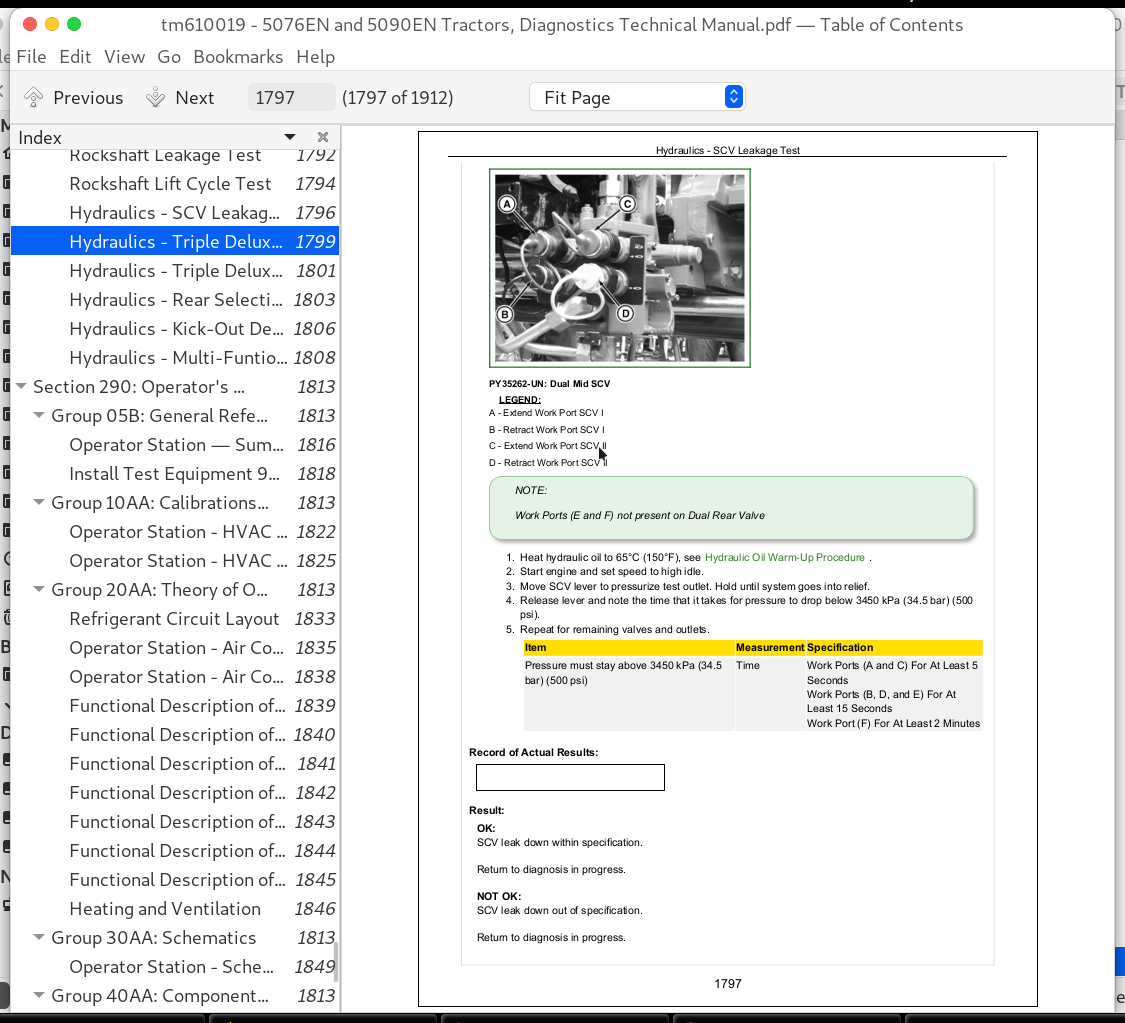
Hydraulics - SCV Leakage Test......1796
Hydraulics - Triple Deluxe Rear SCV Functional Test......1799
Hydraulics - Triple Deluxe Rear SCV Flow Control Test......1801
Hydraulics - Rear Selective Control Valve (SCV) Cable Adjustment......1803
Hydraulics - Kick-Out Detent Pressure Test......1806
Hydraulics - Multi-Funtional Control Cable Adjustment......1808
Section 290: Operator's Station......1813
Group 05B: General References......1813
Operator Station — Summary Of References......1816
Install Test Equipment 90-1......1818
Group 10AA: Calibrations, Preliminary Checks and Operational Checks......1813
Operator Station - HVAC Preliminary Checks......1822
Operator Station - HVAC Operational Checks......1825
Group 20AA: Theory of Operation......1813
Refrigerant Circuit Layout......1833
Operator Station - Air Conditioning System Operation......1835
Operator Station - Air Conditioning Compressor Operation......1838
Functional Description of Components — Condenser......1839
Functional Description of Components—Receiver-Drier......1840
Functional Description of Components—Expansion Valve......1841
Functional Description of Components—Evaporator......1842
Functional Description of Components—A/C Temperature Control Switch......1843
Functional Description of Components—A/C Dual Pressure Switch......1844
Functional Description of Components—Control Knobs for Heating and Cooling......1845
Heating and Ventilation......1846
Group 30AA: Schematics......1813
Operator Station - Schematics......1849
Group 40AA: Component and Connector Information......1813
Operator Station - Component and Connector Information......1852
Group 50AA: Tests and Adjustments......1813
HVAC Circulation Blower Motor Circuit Test......1858
HVAC Compressor Clutch Engagement and Cycle Test......1862
HVAC System Pressure Check......1874
HVAC Temperature Drop Check......1883
Summary of A/C Testing......1888
A/C System Moisture Removal Procedure......1889
Section 299: Special Tools......1890
Group 05B: General References......1890
Special Tools - Summary of References......1892
Group 05C: Dealer Fabricated and Service Tools......1890
DFRW26......1894
DFRW51......1895
DFRW83......1896
DFRW126......1898
DFRW133......1900
DFRW183......1901
Universal Tap-Out Harness......1902
DFLX10 and DFLX11—Test Harnesses......1903
DFLX12—Special Tool for 11-bit and 29-bit CAN BUS......1905
DFLX14—Solenoid Valve Test Harness......1906
John Deere 5076EN and 5090EN Tractors Diagnosis and Tests Service Technical Manual (TM610019)
![]()