
John Deere WL56 4WD Loader (PIN: 1YNWL56___D000509— ) Repair Service Manual (TM14284X19)
Complete Repair Service Technical Manual for John Deere WL56 4WD Loader (PIN: 1YNWL56___D000509— ), with all the shop information to maintain, repair, and rebuild like professional mechanics.
John Deere WL56 4WD Loader (PIN: 1YNWL56___D000509— ) workshop technical manual (repair) includes:
* Numbered table of contents easy to use so that you can find the information you need fast.
* Detailed sub-steps expand on repair procedure information
* Numbered instructions guide you through every repair procedure step by step.
* Notes, cautions and warnings throughout each chapter pinpoint critical information.
* Bold figure number help you quickly match illustrations with instructions.
* Detailed illustrations, drawings and photos guide you through every procedure.
* Enlarged inset helps you identify and examine parts in detail.
tm14284x19 - WL56 4WD Loader (PIN: 1YNWL56___D000509— ) Technical Manual - Repair.pdf
tm14284x19 - WL56 4WD Loader (PIN: 1YNWL56___D000509— ) Technical Manual - Repair.epub
PRODUCT DETAILS:
Total Pages: 904 pages
File Format: PDF/EPUB/MOBI/AZW (PC/Mac/Android/Kindle/iPhone/iPad; bookmarked, ToC, Searchable, Printable)
Language: English
TABLE OF CONTENTS.......1
Section 00: General Information.......13
Group 0001: Safety.......13
Recognize Safety Information.......16
Follow Safety Instructions.......17
Operate Only If Qualified.......18
Wear Protective Equipment.......19
Avoid Unauthorized Machine Modifications.......20
Add Cab Guarding for Special Uses.......21
Inspect Machine.......22
Stay Clear of Moving Parts.......23
Avoid High-Pressure Fluids.......24
Avoid High-Pressure Oils.......25
Work In Ventilated Area.......26
Prevent Fires.......27
Clean Debris from Machine.......28
Prevent Battery Explosions.......29
Handle Chemical Products Safely.......30
Dispose of Waste Properly.......31
Prepare for Emergencies.......32
Use Steps and Handholds Correctly.......33
Start Only From Operator's Seat.......34
Use and Maintain Seat Belt.......35
Prevent Unintended Machine Movement.......36
Avoid Work Site Hazards.......37
Use Special Care When Operating Loader.......39
Keep Riders Off Machine.......40
Avoid Backover Accidents.......41
Avoid Machine Tip Over.......42
Operating on Slopes.......44
Operating or Traveling On Public Roads.......45
Inspect and Maintain ROPS.......46
Add and Operate Attachments Safely.......47
Park and Prepare for Service Safely.......48
Service Cooling System Safely.......49
Service Tires Safely.......50
Remove Paint Before Welding or Heating.......51
Make Welding Repairs Safely.......52
Drive Metal Pins Safely.......53
Section 01: Wheels.......54
Group 0110: Powered Wheels and Fastenings.......54
Wheel Remove and Install.......57
Tire Remove and Install.......59
Section 02: Axles and Suspension Systems.......62
Group 0200: Removal and Installation.......62
TeamMate™ IV Axles.......64
Front Axle Remove and Install.......65
Rear Axle Remove and Install.......68
Axle Oscillating Supports Disassemble and Assemble.......72
Axle Oscillating Supports Wear Bushing Remove and Install.......73
Group 0225: Axle Shafts and U-Joints.......62
Universal Joint and Drive Shaft Remove and Install.......77
Group 0250: Axle Shaft, Bearings, and Reduction Gears.......62
AR15MTL Inboard Planetary Axles.......81
Section 03: Transmission.......82
Group 0300: Removal and Installation.......82
Transmission Remove and Install.......89
Group 0350: Gear, Shafts, and Power Shift Clutches.......82
Torque Converter and Housing Remove and Install.......103
Clutch Pack Remove.......111
Clutch Pack Disassemble and Assemble.......117
Fourth Gear Idler Gear Remove and Install.......126
Third and Fourth Gear Clutch Pack Install.......135
Clutch Pack Install.......135
Output Flange Remove and Install.......143
Output Shaft and Seals Remove and Install.......146
Transmission Speed Sensor Remove and Install.......153
Group 0360: Hydraulic System.......82
Transmission Pump Remove and Install.......168
Transmission Pump Disassemble and Assemble.......181
Transmission Hydraulic Control Valve Remove and Install.......186
Transmission Hydraulic Control Valve Disassemble and Assemble.......191
Torque Converter Pressure Regulator Valve Remove and Install.......194
Section 04: Engine.......196
Group 0400: Removal and Installation.......196
John Deere Engine.......198
Engine Remove and Install.......199
Crankshaft Damper Remove and Install.......205
Serpentine Belt Remove and Install.......206
Section 05: Engine Auxiliary System.......209
Group 0505: Cold Weather Starting Aids.......209
Cold Start Aid—Block Heater Remove and Install—If Equipped.......213
Cold Start Aid—Starting Fluid Nozzle Remove and Install—If Equipped.......216
Cold Start Aid—Starting Fluid Solenoid Remove and Install—If Equipped.......218
Diesel Fired Coolant Heater Remove and Install—If Equipped.......220
Group 0510: Cooling Systems.......209
Charge Air Cooler Remove and Install.......223
Radiator Remove and Install.......224
Hydraulic Oil Cooler Remove and Install.......226
Transmission Oil Cooler Remove and Install.......228
Cooling Package Plenum Remove and Install.......230
Group 0520: Intake System.......209
Air Cleaner Remove and Install.......235
Precleaner Remove and Install—If Equipped.......237
Group 0530: External Exhaust Systems.......209
Muffler Remove and Install.......241
Group 0560: External Fuel Supply Systems.......209
Fuel Tank Remove and Install.......246
Primary Fuel Filter Remove and Install.......249
Final Fuel Filter Remove and Install.......251
Auxiliary Fuel Filter and Water Separator Remove and Install—If Equipped.......252
Section 09: Steering System.......253
Group 0960: Hydraulic System.......253
Orbital Steering Valve Remove and Install.......257
Steering Column Remove and Install.......260
Steering Column Disassemble and Assemble.......262
Steering Cylinders Remove and Install.......265
Steering Cylinder Bushings Remove and Install.......268
Steering Cylinder Disassemble and Assemble.......269
Loader Start-Up Procedure (Steering Cylinder).......274
Section 10: Service Brakes.......275
Group 1011: Active Elements.......275
Service Brake Assembly Remove and Install.......277
Service Brake Pedal Disassemble and Assemble.......278
Group 1060: Hydraulic System.......275
Service Brake Valve Remove and Install.......281
Service Brake Accumulator Remove and Install.......283
Section 11: Park Brake.......285
Group 1111: Active Elements.......285
Park Brake Remove and Install.......288
Group 1160: Hydraulic System.......285
Park Brake Actuator Remove and Install.......293
Park Brake Actuator Disassemble and Assemble.......296
Park Brake Release Solenoid Valve Remove and Install.......298
Section 16: Electrical System.......299
Group 1600: Removal and Installation.......299
Replace Metri-Pack® (Push Type) Connectors.......301
Replace Metri-Pack® Connectors.......302
Replace DEUTSCH® Circular Connectors.......304
Replace DEUTSCH® Rectangular or Triangular Connectors.......306
Install DEUTSCH® Contact.......308
Replace WEATHER PACK® Connector.......310
Install WEATHER PACK® Contact.......312
Replace CINCH™ Connectors.......314
Install CINCH™ Contact.......316
Repair 32 and 48 Way CINCH™ Connectors.......318
Remove Connector Body from Blade Terminals.......322
Section 17: Frame or Supporting Structure.......323
Group 1740: Frame Installation.......323
Welding Major Structure.......326
Separate Engine and Loader Frame.......328
Upper Pivot Bearing and Seals Remove and Install.......332
Lower Pivot Bearing and Seals Remove and Install.......335
Group 1749: Chassis Weights.......323
Concrete Counterweight Remove and Install.......344
Section 18: Operator's Station.......350
Group 1800: Removal and Installation.......350
Cab Remove and Install.......357
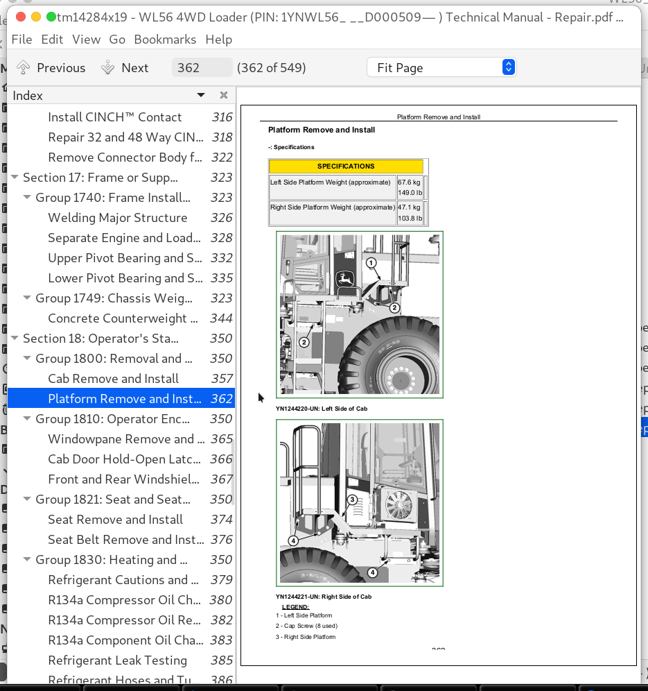
Platform Remove and Install.......362
Group 1810: Operator Enclosure.......350
Windowpane Remove and Install.......365
Cab Door Hold-Open Latch Adjustment.......366
Front and Rear Windshield Wiper Motor Remove and Install.......367
Group 1821: Seat and Seat Belts.......350
Seat Remove and Install.......374
Seat Belt Remove and Install.......376
Group 1830: Heating and Air Conditioning.......350
Refrigerant Cautions and Proper Handling.......379
R134a Compressor Oil Charge Check.......380
R134a Compressor Oil Removal.......382
R134a Component Oil Charge.......383
Refrigerant Leak Testing.......385
Refrigerant Hoses and Tubing Inspection.......386
R134a Refrigerant Recovery/Recycling and Charging Station Installation Procedure.......387
R134a System Recover.......389
R134a System Evacuate.......391
R134a System Charge.......393
R134a System Cleaning Procedures.......395
R134a System Purge.......396
R134a System Flush.......397
Heating and Air Conditioning Module Remove and Install—If Equipped.......400
Heating and Air Conditioning Module Disassemble and Assemble—If Equipped.......402
Heater/Evaporator Coil Remove and Install—If Equipped.......403
Expansion Valve Remove and Install—If Equipped.......406
Freeze Control Switch Remove and Install—If Equipped.......408
Heater Control Valve Remove and Install.......409
Blower Motor Assembly Remove and Install.......411
Receiver-Dryer Remove and Install—If Equipped.......415
Condenser Remove and Install—If Equipped.......417
Air Conditioning High/Low Pressure Switch Remove and Install—If Equipped.......419
Fresh Air Filter Remove and Install—If Equipped.......421
Recirculating Air Filter Remove and Install.......423
Compressor Remove and Install—If Equipped.......424
Section 19: Sheet Metal and Styling.......426
Group 1910: Hood or Engine Enclosure.......426
Hood Remove and Install.......429
Engine Side Shields Remove and Install.......431
Group 1921: Grille and Grille Housing.......426
Grille and Grille Housing Remove and Install.......436
Section 31: Loader.......439
Group 3102: Bucket.......439
Bucket Remove and Install.......443
Welded Bucket Cutting Edges Remove and Install.......445
Bucket Teeth With Segmented Cutting Edge Remove and Install.......446
Bucket Teeth Without Segmented Cutting Edge Remove and Install.......449
Bolt-On Cutting Edges Remove and Install.......451
Cracked Cutting Edge Repair.......453
Group 3140: Frames.......439
Loader Bucket Tilt Linkage Remove and Install.......458
Bucket Linkage Seals and Bushings Remove and Install.......462
Boom Remove and Install.......464
Group 3160: Hydraulic System.......439
Boom Cylinder Remove and Install.......469
Bucket Cylinder Remove and Install.......472
Boom and Bucket Cylinder Disassemble and Assemble.......474
Boom and Bucket Cylinder Bushings Remove and Install.......478
Hydraulic Pump Manifold Remove and Install.......479
Hydraulic Pump Manifold Disassemble and Assemble.......481
Loader Start-Up Procedure.......485
Hydraulic Reservoir Remove and Install.......487
Pilot Control Valve Remove and Install.......491
Pilot Control Valve Disassemble and Assemble.......503
Loader Hydraulic Pump Remove and Install.......510
Loader Hydraulic Pump Disassemble and Assemble.......512
Steering/Loader Hydraulic Pump Remove and Install.......514
Steering/Loader Hydraulic Pump Disassemble and Assemble.......516
Loader Control Valve Remove and Install.......518
Loader Control Valve With Auxiliary Function Remove and Install—If Equipped.......521
Loader Control Valve Disassemble and Assemble.......524
Main Relief Valve Disassemble and Assemble.......526
Circuit Relief With Anticavitation Valve Disassemble and Assemble.......528
General Oil Cleanup Procedure.......530
Hydraulic Component Failure Cleanup Procedure.......533
Section 99: Dealer Fabricated Tools.......536
Group 9900: Dealer Fabricated Tools.......536
DF1025 Oil Supply Flange Back-Off Brackets.......538
DF1026 Preload Clutch Pack Compression Ring Assembly Jig.......539
DF1044 Air Deflector Bushing.......540
DFT1132 Hydraulic Pump Removal and Installation Tool.......541
DFT1347 Axle Pinion Yoke Holder Tool.......542
DFT1348 Shaft Alignment Tool.......543
DFT1349 Steering Cylinder Piston Tool.......545
DFT1350 Boom and Bucket Cylinder Piston Tool.......546
John Deere WL56 4WD Loader (PIN: 1YNWL56___D000509— ) Repair Service Manual (TM14284X19)
![]()