
John Deere 350GLC Excavator (PIN 1FF350GX__E808001— ) (PIN 1FF350GX__D808001— ) (PIN 1FF350GX__C808001— ) Diagnosis and Tests Service Technical Manual (TM12173)
Complete Diagnosis & Tests Technical Manual with electrical wiring diagrams for John Deere 350GLC Excavator (PIN 1FF350GX_ _E808001— ) (PIN: 1FF350GX_ _D808001— ) (PIN 1FF350GX__C808001— ), with workshop information to maintain, diagnose, and rebuild like professional mechanics.
John Deere 350GLC Excavator (PIN 1FF350GX_ _E808001— ) (PIN: 1FF350GX_ _D808001— ) (PIN 1FF350GX__C808001— ) workshop Diagnosis & Tests technical manual includes:
* Numbered table of contents easy to use so that you can find the information you need fast.
* Detailed sub-steps expand on repair procedure information
* Numbered instructions guide you through every repair procedure step by step.
* Troubleshooting and electrical service procedures are combined with detailed wiring diagrams for ease of use.
* Notes, cautions and warnings throughout each chapter pinpoint critical information.
* Bold figure number help you quickly match illustrations with instructions.
* Detailed illustrations, drawings and photos guide you through every procedure.
* Enlarged inset helps you identify and examine parts in detail.
tm12173 - John Deere 350GLC Excavator (PIN 1FF350GX_ _E808001— ) (PIN: 1FF350GX_ _D808001— ) (PIN 1FF350GX__C808001— ) Operation & Test Technical Manual.pdf
tm12197 - John Deere Excavadora 350GLC (PIN: 1FF350GX_ _E808001— ) (PIN: 1FF350GX_ _D808001— ) (PIN: 1FF350GX_ _C808001— ).pdf
tm12185 - John Deere Excavatrice 350GLC.pdf
tm12318 - John Deere Escavadeira 350GLC.pdf
PRODUCT DETAILS
Total Pages: 1,491 pages
File Format: PDF/EPUB/MOBI/AZW (PC/Mac/Android/Kindle/iPhone/iPad; bookmarked, ToC, Searchable, Printable)
Category: Operation and Test
Language: English Spanish French Portuguese
Published on 2019/11/26
TABLE OF CONTENTS....1
Section 9000: General Information....23
Group 01: Safety....23
Recognize Safety Information....26
Follow Safety Instructions....27
Operate Only If Qualified....28
Wear Protective Equipment....29
Avoid Unauthorized Machine Modifications....30
Add Cab Guarding For Special Uses....31
Inspect Machine....32
Stay Clear of Moving Parts....33
Avoid High-Pressure Fluids....34
Avoid High-Pressure Oils....35
Work In Ventilated Area....36
Prevent Fires....37
Prevent Battery Explosions....38
Handle Chemical Products Safely....39
Decommissioning — Proper Recycling and Disposal of Fluids and Components....40
Exhaust Filter Ash Handling and Disposal....41
Prepare for Emergencies....42
Clean Debris from Machine....43
Use Steps and Handholds Correctly....44
Start Only From Operator's Seat....45
Use and Maintain Seat Belt....46
Prevent Unintended Machine Movement....47
Avoid Work Site Hazards....48
Keep Riders Off Machine....50
Avoid Backover Accidents....51
Inspect and Maintain ROPS....52
Operating or Traveling On Public Roads....53
Avoid Machine Tip Over and Machine Damage....54
Use Special Care When Lifting Objects....56
Add and Operate Attachments Safely....57
Park and Prepare for Service Safely....58
Service Cooling System Safely....59
Remove Paint Before Welding or Heating....60
Make Welding Repairs Safely....61
Drive Metal Pins Safely....62
Clean Exhaust Filter Safely....63
Section 9001: Diagnostics....66
Group 10: Main Controller (MCZ) Diagnostic Trouble Codes....73
Main Controller (MCZ) Diagnostic Trouble Codes....73
Controller Area Network 0 (CAN 0) Circuit Diagnostics....74
Controller Area Network 1 (CAN 1) Circuit Diagnostics....75
Interface Controller Area Network (N-CAN) Diagnostics....76
Engine Controller Area Network (Engine CAN) Diagnostics....77
011000.02 - Abnormal EEPROM....66
011001.02 - Abnormal RAM....66
011002.02 - Abnormal A/D Converter....66
011003.03 - Abnormal Sensor Voltage....66
011004.02 - CAN Communication Error 1....66
011005.02 - CAN Communication Error 2....66
011006.02 - Engine Controller Communication Error....66
011007.02 - (CAN 0) Data Converter Communication Error 1....66
011008.02 - (CAN 1) Data Converter Communication Error 2....66
011009.02 - (CAN 0) Monitor Controller Communication Error 1....66
011010.02 - (CAN 1) Monitor Controller Communication Error 2....66
011100.02 - Abnormal Engine Speed....66
011101.03 - Engine Control Dial Sensor Circuit High....66
011101.04 - Engine Control Dial Sensor Circuit Low....66
011200.03 - Pump 1 Delivery Pressure Sensor Circuit High Input....66
011200.04 - Pump 1 Delivery Pressure Sensor Circuit Low....66
011201.03 - Fan Pump Delivery Pressure Sensor Circuit High....66
011201.04 - Fan Pump Delivery Pressure Sensor Circuit Low....66
011202.03 - Pump 2 Delivery Pressure Sensor Circuit High....66
011202.04 - Pump 2 Delivery Pressure Sensor Circuit Low....66
011206.03 - Pump 1 Control Pressure Sensor Circuit High....66
011206.04 - Pump 1 Control Pressure Sensor Circuit Low....66
011208.03 - Pump 2 Control Pressure Sensor Circuit High....66
011208.04 - Pump 2 Control Pressure Sensor Circuit Low....66
011301.03 - Swing Pressure Sensor Circuit High....66
011301.04 - Swing Pilot Pressure Sensor Circuit Low....66
011302.03 - Boom Up Pressure Sensor Circuit High....67
011302.04 - Boom Up Pressure Sensor Circuit Low....67
011303.03 - Arm In Pressure Sensor Circuit High....67
011303.04 - Arm In Pressure Sensor Circuit Low....67
011304.03 - Travel Pressure Sensor Circuit High....67
011304.04 - Travel Pressure Sensor Circuit Low....67
011307.03 - Front Attachment Pressure Sensor Circuit High....67
011307.04 - Front Attachment Pressure Sensor Circuit Low....67
011400.02 - Pump 2 Control Rate Limit Solenoid Feedback Abnormal....67
011400.03 - Pump 2 Control Rate Limit Solenoid Feedback High Current....67
011400.04 - Pump 2 Control Rate Limit Solenoid Feedback Low Current....67
011401.02 - Torque Control Solenoid Abnormal Feedback....67
011401.03 - Torque Solenoid Feedback High Current....67
011401.04 - Torque Solenoid Valve Feedback Low Current....67
011402.02 - Dig Regenerative Solenoid Feedback Current Abnormal....67
011402.03 - Dig Regenerative Solenoid Feedback Current High....67
011402.04 - Dig Regenerative Solenoid Feedback Current Low....67
011403.02 - Arm Regenerative Solenoid Feedback Current Abnormal....67
011403.03 - Arm Regenerative Solenoid Feedback Current High....67
011403.04 - Arm Regenerative Solenoid Feedback Current Low....67
011404.02 - Power Dig Solenoid Feedback Current Abnormal....67
011404.03 - Power Dig Solenoid Feedback Current High....67
011404.04 - Power Dig Solenoid Feedback Current Low....67
011405.02 - Travel Speed Solenoid Feedback Current Abnormal....67
011405.03 - Travel Speed Solenoid Feedback Current High....67
011405.04 - Travel Speed Solenoid Feedback Current Low....67
011412.02 - Hydraulic Fan Control Solenoid Feedback Current Abnormal....67
011412.03 - Hydraulic Fan Control Solenoid Feedback Current High....67
011412.04 - Hydraulic Fan Control Solenoid Feedback Current Low....67
011457.02 - 2-Speed Activation Solenoid Disconnected or Not Present....67
011458.02 - Selector Valve Solenoid Valve Disconnected or Not Present....67
011459.02 - Idle Stop Relay Circuit Malfunction....67
015011.03 - Hydraulic Oil Temperature Sensor Circuit High Input (Pilot)....67
015011.04 - Hydraulic Oil Temperature Sensor Circuit Low Input (Pilot)....68
015016.03 - Right Analog Stroke Sensor Circuit High Input....68
015016.04 - Right Analog Stroke Sensor Circuit Low Input....68
011810.03 - Electric Lever Operating Pressure Sensor 1 High Voltage....68
011810.04 - Electric Lever Operating Pressure Sensor 1 Low Voltage....68
011812.02 - OPT Electric Lever 1 Neutral Abnormal....68
011813.02 - OPT Electric Lever 1 Abnormal Operation....872
011816.02 - OPT Solenoid 1 Feedback Abnormal....68
011816.03 - OPT Solenoid 1 Feedback Current High....68
011816.04 - OPT Solenoid 1 Feedback Current Low....68
011817.02 - OPT Solenoid 2 Feedback Abnormal....68
011817.03 - OPT Solenoid 2 Feedback Current High....68
011817.04 - OPT Solenoid 2 Feedback Current Low....68
011901.03 - Hydraulic Oil Temperature Sensor Circuit High....68
011901.04 - Hydraulic Oil Temperature Sensor Circuit Low....68
020009.02 - Hydraulic Oil Cooling System Abnormal....68
020010.02 - Abnormal Exhaust Filter....882
020011.02 - Electric Lever Alarm....68
020303.02 - Electric Lever Pilot Cut Alarm....68
020013.02 - Hydraulic Fan Low Rotation Error Warning....68
020062.02 - Hydraulic Oil Temperature Alarm....68
Group 20: Engine Control Unit (ECU) Diagnostic Trouble Codes (Level 14 Controller)....262
Engine Control Unit (ECU) Diagnostic Trouble Codes (Level 14 Controller)....262
000171.03 - Intake Air Temperature Sensor Out of Range High....68
000171.04 - Intake Air Temperature Sensor Out of Range Low....68
000647.05 - Proportional Fan Speed Solenoid Driver Open....68
000647.31 - Fan Manual Reverse Mode Input Active Too Long....68
000898.09 - Engine Speed Request Not Received or Timed Out....68
001638.09 - Hydraulic Oil Temperature Message Not Received or Timed Out....68
003511.03 - Fan Speed Sensor Out of Range High....68
003511.04 - Fan Speed Sensor Out of Range Low....68
020106.02 - Air Cleaner Restriction Alarm....68
Group 21: Engine Control Unit (ECU) Diagnostic Trouble Codes (Level 21 Controller)....68
Engine Control Unit (ECU) Diagnostic Trouble Codes....281
000107.00 - Air Filter Differential Pressure High—Most Severe Level....69
000111.01 - Coolant Level Low—Most Severe Level....69
000111.18 - Coolant Level Low—Moderately Severe Level....69
000158.01 - Battery Voltage Low....69
000190.00 - Engine Speed High—Most Severe Level....69
000627.18 - Battery Voltage Below Normal—Moderately Severe Level....69
000647.05 - Proportional Fan Speed Valve Solenoid Driver Open....69
000647.06 - Proportional Fan Speed Valve Solenoid Driver Short....69
000647.16 - Manual Purge Mode Switch Active Too Long....69
000898.09 - Requested Speed/Speed Limit....69
001110.31 - Engine Protection System has Shutdown....69
001568.02 - Torque Curve Selection....69
001638.09 - Hydraulic Temperature....69
001639.00 - Fan Speed High—Moderately Severe Level....69
001639.01 - Fan Speed Low—Most Severe Level....69
001639.18 - Fan Speed Low—Moderately Severe Level....69
002000.13 - Security Violation....69
002003.09 - CAN Timeout or Invalid Data....69
002003.13 - Security Violation....69
002005.09 - Abnormal Update Rate....69
002017.09 - CAN Timeout or Invalid Data....69
002017.13 - Security Violation....69
002146.09 - HCI Pump Message Missing....69
002883.03 - Idle Switch Voltage Out of Range High....69
002883.04 - Idle Switch Voltage Out of Range Low....69
003587.05 - Cold Start Aid Solenoid Open....69
003587.06 - Cold Start Aid Solenoid Short....69
003701.14 - Exhaust Filter Cleaning Not Required....69
065372.05 - Proportional Fan Speed Valve Solenoid Driver Open....69
065372.06 - Proportional Fan Speed Valve Solenoid Driver Short....69
Group 30: Monitor Controller (DSZ) Diagnostic Trouble Codes....336
Monitor Controller (DSZ) Diagnostic Trouble Codes....336
013002.02 - ECU Communication Error....70
013003.02 - Main Controller (MCZ) Communication Error 1....70
013004.02 - Main Controller (MCZ) Communication Error 2....70
013005.02 - Monitor Controller (DSZ) Communication Error 1....70
013006.02 - Monitor Controller (DSZ) Communication Error 2....70
013007.02 - Machine Controller (BCZ) Communication Error....70
020113.02 - System Error Alarm....70
Group 40: Information Controller (ICZ) Diagnostic Trouble Codes....345
Information Controller (ICZ) Diagnostic Trouble Codes....345
013311.03 - Fuel Level Sensor Open Circuit....70
013311.04 - Fuel Level Sensor Shorted Circuit....70
013334.02 - Radiator Coolant Error....70
014001.02 - Flash Memory Read/Write Error....70
014002.02 - External RAM Read/Write Error....70
014003.02 - Abnormal EEPROM....70
014006.02 - Communication Terminal : Communication Error....70
014008.02 - Abnormal Internal RAM....70
014021.02 - Communication Terminal Security Error....70
014022.02 - SIM Card Error....70
014023.02 - Security Error....70
020101.02 - Engine Warning Alarm....70
020102.02 - Engine Oil Pressure Alarm....70
020103.02 - Alternator Alarm....70
020105.02 - Hydraulic Oil Filter Restriction Alarm....70
020109.02 - Pilot Control Shut-Off Lever Alarm....70
020110.02 - Fuel Filter Restriction Alarm....70
020133.02 - Crane Function Alarm....70
020137.02 - Exhaust Filter Alarm....70
020141.02 - Exhaust Temperature Alarm....70
020142.02 - Intake Air Temperature Alarm....70
020145.02 - Boost Temperature Increase Alarm....70
020146.02 - Fuel Temperature Increase Alarm....70
020149.02 - EGR Gas Temperature Alarm....70
Group 50: Air Conditioner Controller (ACF) Diagnostic Trouble Codes....377
Air Conditioner Controller (ACF) Diagnostic Trouble Codes....377
11 - Open Circuit In Air Recirculation Sensor....71
12 - Short-Circuited Air Recirculation Sensor....71
13 - Open Circuit In Ambient Air Temperature Sensor....71
14 - Short-Circuited Ambient Air Temperature Sensor....71
18 - Short-Circuited Solar Radiation Sensor....71
21 - Open Circuit In Air Conditioner Freeze Control Switch....71
22 - Short-Circuited Air Conditioner Freeze Control Switch....71
43 - Abnormal Air Conditioner And Heater Blower Port Change Servomotor....71
44 - Abnormal Air Conditioner And Heater Mixer Servomotor....71
51 - Abnormal Air Conditioner High/Low Pressure Switch....71
91 - Communication Error....71
92 - CAN Bus Off Error....71
Section 9005: Operational Checkout Procedure....392
Group 10: Operational Checkout Procedure....392
Operational Checkout....460
Section 9010: Engine....527
Group 05: Theory of Operation....872
Engine Identification....531
John Deere Engine....553
Engine Fuel System Component Location....535
Engine Cooling System Component Location....538
Cold Weather Starting Aid....540
Engine Speed Control System Operation....872
Group 15: Diagnostic Information....527
John Deere Engine....553
Group 20: Adjustments....527
John Deere Engine....553
Group 25: Tests....527
John Deere Engine....553
Radiator Temperature Differential Check....554
Section 9015: Electrical System....557
Group 05: System Information....557
Electrical Diagram Information....570
Group 10: System Diagrams....557
Explanation of Wire Markings....579
Fuse and Relay Specifications....580
System Functional Schematic, Component Location, and Wiring Diagram Master Legend....589
System Functional Schematic....599
Cab Harness (W1) Component Location....642
Cab Harness (W1) Wiring Diagram....649
Machine Harness (W2) Component Location....658
Machine Harness (W2) Wiring Diagram....662
Monitor Harness (W3) Component Location....669
Monitor Harness (W3) Wiring Diagram....670
Engine Harness (W4) Component Location....672
Engine Harness (W4) Wiring Diagram....680
Engine Interface Harness (W5) Component Location....684
Engine Interface Harness (W5) Wiring Diagram....687
Pump Harness (W8) Component Location....691
Pump Harness (W8) Wiring Diagram....692
Exhaust Filter Parked Cleaning Switch Harness (W9) Component Location....694
Exhaust Filter Parked Cleaning Switch Harness (W9) Wiring Diagram....695
Service ADVISOR™ Remote (SAR) Harness (W10) Component Location....696
Service ADVISOR™ Remote (SAR) Switch Harness (W10) Wiring Diagram....697
Pilot Shutoff Switch Harness (W11) Component Location....698
Pilot Shutoff Switch Harness (W11) Wiring Diagram....699
Auxiliary Fuse Box Harness (W13) Component Location....700
Auxiliary Fuse Box Harness (W13) Wiring Diagram....701
Heated Air Seat Harness (W14) Component Location....703
Heated Air Seat Harness (W14) Wiring Diagram....705
Multi-Function Pilot Control Lever Harness (W15) Component Location....706
Multi-Function Pilot Control Lever Harness (W15) Wiring Diagram....708
Travel Alarm Cancel Switch Harness (W16) Component Location....709
Travel Alarm Cancel Switch Harness (W16) Wiring Diagram....710
Attachment Harness (W17) Component Location....711
Attachment Harness (W17) Wiring Diagram....713
Alternator Harness (W18) Component Location....714
Alternator Harness (W18) Wiring Diagram....715
Rear Camera Harness (W19) Component Location....716
Rear Camera Harness (W19) Wiring Diagram....717
Pilot Shutoff Valve Harness (W21) Component Location....718
Pilot Shutoff Valve Harness (W21) Wiring Diagram....719
Auxiliary 3-Button Cancel Switch Harness (W22) Component Location....720
Auxiliary 3-Button Cancel Switch Harness (W22) Wiring Diagram....721
Reversing Fan Switch Harness (W23) Component Location....722
Reversing Fan Switch Harness (W23) Wiring Diagram....723
Seat Heater Switch Harness (W24) Component Location....724
Seat Heater Switch Harness (W24) Wiring Diagram....725
Travel Alarm Harness (W26) Component Location....726
Travel Alarm Harness (W26) Wiring Diagram....727
Starter Harness (W27) Component Location....728
Starter Harness (W27) Wiring Diagram....729
Starter Switch Harness (W29) Component Location....731
Starter Switch Harness (W29) Wiring Diagram....732
Air Throttle Valve Harness (W30) Component Location....733
Air Throttle Valve Harness (W30) Wiring Diagram....734
2-Speed Harness (W32) Component Location....735
2-Speed Harness (W32) Wiring Diagram....736
Heater and Air Conditioner Harness (W41) Component Location....737
Heater and Air Conditioner Harness (W41) Wiring Diagram....739
Alternator Jumper Harness (W42) Component Location....740
Alternator Jumper Harness (W42) Wiring Diagram....741
Starter Protection Jumper Harness (W43) Component Location....742
Starter Protection Jumper Harness (W43) Wiring Diagram....743
Auxiliary Solenoid Harness (W61) Component Location....744
Auxiliary Solenoid Harness (W61) Wiring Diagram....746
Auxiliary Function Lever (AFL) Harness (W75) Component Location....748
Auxiliary Function Lever (AFL) Harness (W75) Wiring Diagram....750
Auxiliary Function Lever (AFL) Solenoid Harness (W76) Component Location....751
Auxiliary Function Lever (AFL) Solenoid Harness (W76) Wiring Diagram....753
Modular Telematics Gateway (MTG) Harness (W6002) Component Location....755
Modular Telematics Gateway (MTG) Harness (W6002) Wiring Diagram....756
Satellite (SAT) Harness (W6003) Component Location....757
Satellite (SAT) Harness (W6003) Wiring Diagram....758
Group 15: Sub-System Diagnostics....559
Controller Area Network (CAN) Theory of Operation....872
Starting and Charging Circuit Theory of Operation....872
Monitor Controller (DSZ) Circuit Theory of Operation....872
Engine Control Unit (ECU) Circuit Theory of Operation....872
Exhaust Aftertreatment Circuit Theory of Operation....872
Main Controller (MCZ) Circuit Theory of Operation....872
Machine Controller (BCZ) Circuit Theory of Operation....872
Windshield Wiper and Washer Circuit Theory of Operation....872
Lighting Circuit Theory of Operation....872
Travel Alarm Circuit Theory of Operation....872
Pilot Shutoff Circuit Theory of Operation....872
Attachment Control Circuit Theory of Operation....872
Group 16: Monitor Operation....872
Service Menu....862
Troubleshooting....863
Monitoring....864
Controller Version....870
Issued Warning Record....871
Operation....872
Machine Setting....873
Monitor Setting....878
Alarm Setting....881
Exhaust Filter....882
Maintenance Mode....883
Rear View Camera Troubleshooting....884
Group 20: References....560
Reading Diagnostic Trouble Codes with Monitor Display....888
Service ADVISOR™ Diagnostic Application....889
Service ADVISOR™ Connection Procedure....890
Reading Diagnostic Trouble Codes with Service ADVISOR™ Diagnostic Application....893
MPDr Application....896
MPDr Connection Procedure....897
Fuse Test....899
Relay Test....910
Pressure Sensor Test....911
Solenoid Test....914
Proportional Solenoid Test....915
Temperature Sensor Test....916
Alternator Test....917
Controller Area Network (CAN) Circuit Test....919
Electrical Component Checks....928
Engine Electrical Component Specifications....935
Battery Remove and Install....936
Rear Cover Remove and Install....938
Main Controller (MCZ) Remove and Install....940
Machine Controller (BCZ) Remove and Install....943
Engine Control Unit (ECU) Remove and Install....946
Data Converter Remove and Install....948
Monitor Controller (DSZ) Remove and Install....949
Air Conditioner Controller (ACF) Remove and Install....951
Key Switch Remove and Install....952
Right Switch Console Remove and Install....953
Left Switch Console Remove and Install....955
Travel Alarm Remove and Install....957
Heater Control Disable and Enable....958
Disconnect Tab Retainer Connectors....959
Disconnecting Spring Wire Clip Connectors....960
Replace DEUTSCH™ Connectors....961
Replace DEUTSCH™ Rectangular or Triangular Connectors....963
Install DEUTSCH™ Contact....965
Replace WEATHER PACK™ Connector....967
Install WEATHER PACK™ Contact....969
Replace (Pull Type) Metri-Pack™ Connectors....971
Replace (Push Type) Metri-Pack™ Connectors....973
Replace CINCH™ Connectors....974
Install CINCH™ Contact....976
Repair 32 and 48 Way CINCH™ Connectors....978
Remove Connector Body from Blade Terminals....982
Section 9020: Power Train....983
Group 05: Theory of Operation....872
Track Adjuster and Recoil Spring Operation....985
Travel Gearbox Operation....986
Group 15: Diagnostic Information....983
Noisy or Loose Track Chain....983
Tight Track Chain....983
Frequent Track Chain Sag Adjustment Required....983
Excessive Oil Leakage From Front Idler, Track Rollers, or Carrier Rollers....983
Bent Track Shoes....983
“Popping” of Track....983
Cracked Track Link....983
Chipped Link Rails....983
Individual Undercarriage Component Wear....983
Measure Swing Bearing Wear....1004
Section 9025: Hydraulic System....1008
Group 05: Theory of Operation....872
Hydraulic System Operation....1013
Fan Drive Hydraulic System Operation....1014
Pilot System Operation....1018
Pilot Pump, Pressure Regulating Valve and Filter Operation....1019
Pilot Shutoff Solenoid Valve Operation....1021
Pilot Control Valve Operation....1055
Travel Pilot Control Valve Operation....1055
Pilot Operation of Control Valve Operation....1055
Pilot Signal Manifold Operation....1035
Pump 1, Pump 2, and Drive Gear Case Operation....1044
Pump 1 and Pump 2 Regulator Operation....1047
Engine Speed Sensing Control Circuit Operation....1053
Control Valve Operation....1055
Control Valve Check Valves Identification and Operation....1070
Main Relief Valve Circuit Operation....1074
Circuit Relief and Anticavitation Valve Operation....1084
Travel Flow Combiner Valve Operation....1086
Auxiliary Flow Combiner Valve and Bypass Shutoff Valve Operation....1088
Boom Lower Meter-In Cut Valve Operation....1093
Boom Regenerative Valve Circuit Operation....1097
Dig Regenerative Valve Circuit Operation....1100
Arm Regenerative Valve Circuit Operation....1108
Bucket Regenerative Valve Circuit Operation....1118
Boom and Arm Reduced Leakage Valves Operation....1121
Arm 1 Flow Rate Control Valve Circuit Operation....1123
Arm 2 Flow Rate Control Valve Circuit Operation....1127
Bucket Flow Rate Control Valve Circuit Operation....1131
Boom Flow Rate Control Valve Circuit Operation....1135
Swing Reduction Gearbox Operation....1139
Swing Motor, Crossover Relief Valve, and Make-Up Check Valve Operation....1140
Swing Motor Damper Valve....1144
Swing Motor Park Brake Release Circuit Operation....1155
Center Joint Operation....1156
Travel Motor and Park Brake Valve Operation....1157
Travel Motor Speed Circuit Operation....1165
Cylinder Operation....1172
Return Filter Operation....1174
Auxiliary System Operation....1175
Auxiliary Pilot Control Valve Operation....1176
Flow Rate Select Solenoid Valve Operation....1183
Secondary Auxiliary Relief Valve Solenoid Valve Operation....1185
Secondary Auxiliary Relief Control Valve Operation....1186
Secondary Auxiliary Relief Valve Operation....1187
Selector Valve Solenoid Valve Operation....1188
Selector Valve Operation....1189
Auxiliary Shuttle Valve Operation....1191
Auxiliary High Flow Line Kit Operation....1193
Two Way Solenoid Kit Operation....1197
Two Pump Combined Flow Kit Operation....1200
Secondary Auxiliary Relief Kit Operation....1202
Low Flow Kit Operation....1205
Group 15: Diagnostic Information....1009
All Hydraulic Functions Slow....1009
Hydraulic Oil Overheats....1009
No Hydraulic Functions....1009
No Hydraulic Functions—Electrical Checks....1009
Function Does Not Stop When Control Lever Released....1009
Load Drifts Down When Control Lever is in Neutral Position....1009
Load Falls When Control Valve is Actuated To Raise Load....1009
H/P (High Power) Function Does Not Operate, PWR (Power) Mode is Normal....1009
Boom Down Does Not Function, Moves Slowly, or Is Erratic, All Other Functions Normal....1009
Arm In Does Not Function, Moves Slowly, or Is Erratic, All Other Functions Normal....1009
Swing Speed Slow During Arm In Function....1009
Boom Cannot Raise Track Off Ground....1009
Swing Function Does Not Operate in Both Directions....1010
Swing Speed Slow in Both Directions....1010
Swing Speed Slow or Does Not Operate in One Direction....1010
Upperstructure Drift With Swing Valve in Neutral....1010
Machine Freewheels Down an Incline....1010
Track Will Not Move in Either Direction....1010
Machine Mistracks....1010
Machine Mistracks Left During Combined Travel and Dig Functions....1010
Machine Will Not Shift Into Fast (rabbit) Speed....1010
Pump 1, Pump 2, and Pilot Pump Line Identification....1270
Control Valve Line Identification....1271
Swing Motor Line Identification....1275
Pilot Control Valve-to-Pilot Signal Manifold Component Location—Excavator Pattern....1276
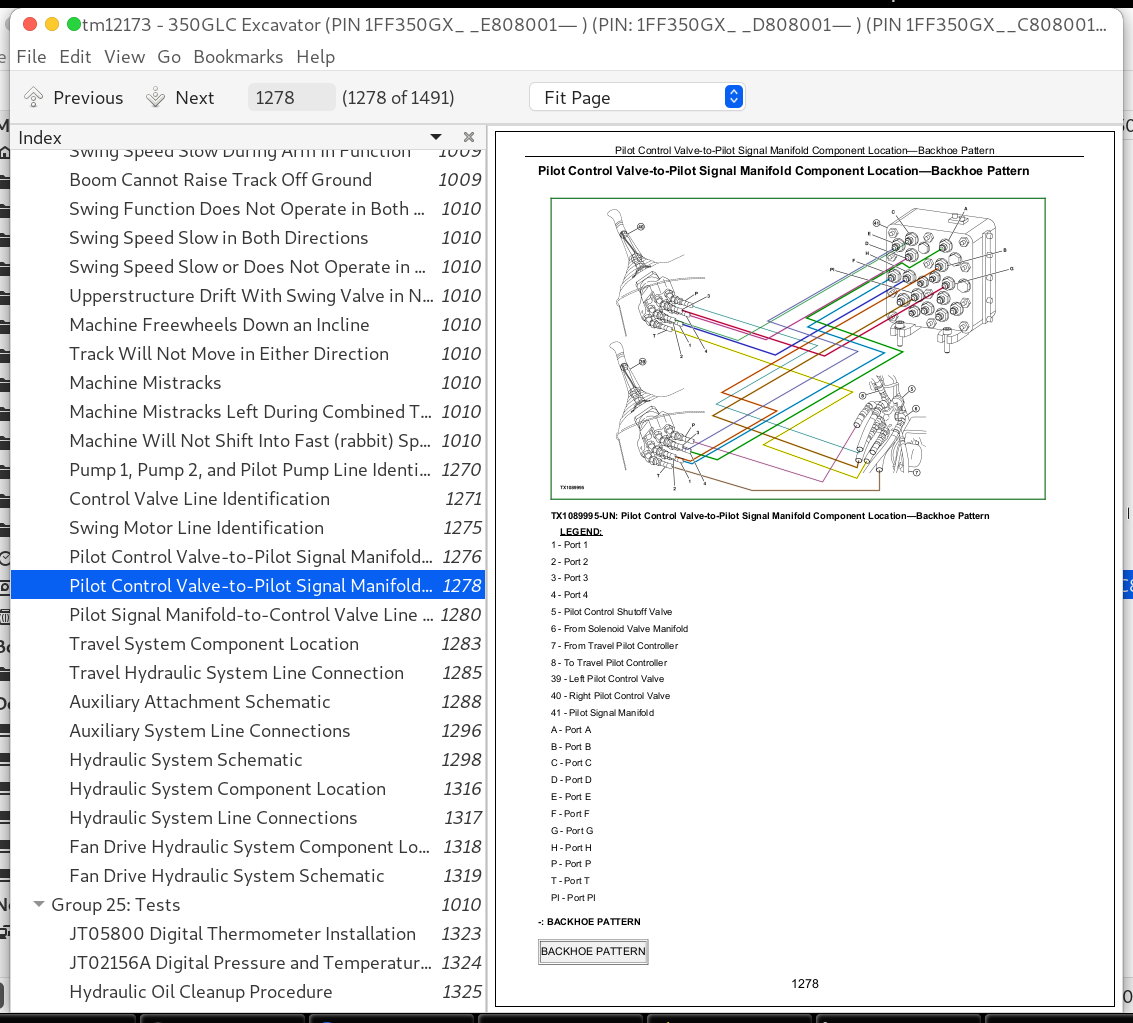
Pilot Control Valve-to-Pilot Signal Manifold Component Location—Backhoe Pattern....1278
Pilot Signal Manifold-to-Control Valve Line Connection....1280
Travel System Component Location....1283
Travel Hydraulic System Line Connection....1285
Auxiliary Attachment Schematic....1288
Auxiliary System Line Connections....1296
Hydraulic System Schematic....1298
Hydraulic System Component Location....1316
Hydraulic System Line Connections....1317
Fan Drive Hydraulic System Component Location....1318
Fan Drive Hydraulic System Schematic....1319
Group 25: Tests....1010
JT05800 Digital Thermometer Installation....1323
JT02156A Digital Pressure and Temperature Analyzer Kit Installation....1324
Hydraulic Oil Cleanup Procedure....1325
Hydraulic Oil Tank Pressure Release Procedure....1328
Hydraulic Oil Warm-Up Procedure....1329
Pilot Pressure Regulating Valve Test and Adjustment....1332
Control Valve Spool Actuating Pilot Pressure Test....1336
Dig Regenerative Solenoid Valve Test and Adjustment....1339
Arm Regenerative Solenoid Valve Test and Adjustment....1348
Power Dig Solenoid Valve Test and Adjustment....1357
Travel Speed Solenoid Valve Test and Adjustment....1366
Torque Control Solenoid Valve Test and Adjustment....1371
Pump Control Pilot Pressure Signal Test....1376
Main Relief and Power Dig Valve Test and Adjustment....1379
Circuit Relief Valve Test and Adjustment....1385
Swing Motor Crossover Relief Valve Test and Adjustment....1391
Travel Motor Crossover Relief Valve Test and Adjustment....1395
Pump Regulator Test and Adjustment—Minimum Flow....1400
Pump Regulator Test and Adjustment—Maximum Flow....1403
Pump Flow Test....1406
Comprehensive Pump Flow Test....1410
Swing Motor Leakage Test....1416
Travel Motor Leakage Test....1419
Cylinder Drift Test—Boom, Arm, and Bucket....1423
Upperstructure Drift Test....1426
Fan Drive Pump Flow Test....1429
Fan Speed Test....1432
Section 9031: Heating and Air Conditioning....1435
Group 05: Theory of Operation....872
Air Conditioning System Cycle of Operation....1438
Group 15: Diagnostic Information....1435
No Air Flow From Heater and Air Conditioner Vents....1435
Air Conditioning System Does Not Operate....1435
Air Conditioning Does Not Cool Interior of Cab....1435
Air Conditioning Runs Constantly, Too Cold....1435
Interior Windows Continue to Fog Using Air Conditioner....1435
Heater System Does Not Operate....1435
Heater Does Not Warm Interior of Cab....1435
Interior Windows Continue to Fog Using Heater....1435
Heater and Air Conditioner Component Location....1469
Group 25: Tests....1435
Refrigerant Cautions and Proper Handling....1471
Heater and Air Conditioner Operational Checks....1472
Air Conditioner Compressor Clutch Test....1475
Refrigerant Leak Test....1476
Refrigerant Hoses and Tubing Inspection....1477
Air Conditioner Compressor Belt Check and Adjustment....1478
Air Conditioner High/Low-Pressure Switch Test....1479
Air Conditioner Freeze Control Switch Test....1482
R134a Air Conditioning System Test....1483
Operating Pressure Diagnostic Chart....1486
Section 9900: Dealer Fabricated Tools....1487
Group 99: Dealer Fabricated Tools....1487
DFT1218 Split Flange Hose Cap....1489
John Deere 350GLC Excavator (PIN 1FF350GX__E808001— ) (PIN 1FF350GX__D808001— ) (PIN 1FF350GX__C808001— ) Diagnosis and Tests Service Technical Manual (TM12173)
![]()