
John Deere 1745 and 1755 Planters Frame Repair Service Manual (TM609219)
Complete Repair Service Technical Manual for John Deere 1745 and 1755 Planters Frame, with all the shop information to maintain, diagnose, repair, and rebuild like professional mechanics.
John Deere 1745 and 1755 Planters Frame workshop technical manual (repair) includes:
* Numbered table of contents easy to use so that you can find the information you need fast.
* Detailed sub-steps expand on repair procedure information
* Numbered instructions guide you through every repair procedure step by step.
* Troubleshooting and electrical service procedures are combined with detailed wiring diagrams for ease of use.
* Notes, cautions and warnings throughout each chapter pinpoint critical information.
* Bold figure number help you quickly match illustrations with instructions.
* Detailed illustrations, drawings and photos guide you through every procedure.
* Enlarged inset helps you identify and examine parts in detail.
tm609219 - 1745 and 1755 Planter Repair Technical Manual.pdf
tm609219 - 1745 and 1755 Planter Repair Technical Manual.epub
PRODUCT DETAILS:
Total Pages: 601 pages
File Format: PDF/EPUB/MOBI/AZW (PC/Mac/Android/Kindle/iPhone/iPad; bookmarked, ToC, Searchable, Printable)
Language: English
MAIN SECTIONS
Foreword
General Information
Safety
Lubricants
General Information
Vacuum System
Vacuum System
Central Commodity System
Seed Tanks and Manifolds
Seed Delivery Hose
Central Commodity System Fan
Electrical
Connector Repair
Relays, Sensors, and Switches
Lighting Repair
Control Units
Drives
Specifications
Seed Drive Transmissions
Drill Shafts
Variable Rate Drive
Hitch and Frame
Repair and Welding
Wheel Module Repair
Row Markers
Hydraulics
General Information
Motors
Cylinders
Valves
Miscellaneous
Fertilizer Systems
Liquid Fertilizer System
Dry Fertilizer System
Pneumatic Down Force
General Information
Pneumatic Down Force
Miscellaneous
Polyethylene Tank Repair
Dealer Fabricated Tools
TABLE OF CONTENTS................1
Section 10: General Information................12
Group 05: Safety................12
Recognize Safety Information................15
Understand Signal Words................16
Follow Safety Instructions................17
Handle Fluids Safely—Avoid Fires................18
Prevent Battery Explosions................19
Handling Batteries Safely................20
Prevent Acid Burns................22
Prepare for Emergencies................24
Avoid Harmful Asbestos Dust................25
Practice Safe Maintenance................26
Avoid High-Pressure Fluids................28
Park Machine Safely................29
Support Machine Properly................30
Wear Protective Clothing................31
Handle Agricultural Chemicals Safely................32
Work in Clean Area................34
Service Machines Safely................35
Work In Ventilated Area................36
Illuminate Work Area Safely................37
Replace Safety Signs................38
Use Proper Lifting Equipment................39
Remove Paint Before Welding or Heating................40
Avoid Heating Near Pressurized Fluid Lines................41
Service Tires Safely................42
Use Proper Tools................43
Construct Dealer-Made Tools Safely................44
Decommissioning — Proper Recycling and Disposal of Fluids and Components................45
Live With Safety................46
Servicing Electronic Control Units................47
Welding Near Electronic Control Units................48
Precautions for Welding................326
Keep Electronic Control Unit Connectors Clean................51
Group 10: General Specifications................535
For Complete Service Information................53
Glossary of Terms................54
Trademarks................55
Regions and Country Versions................56
Group 15: Technical Specific References................13
Unauthorized Modifications................59
Specifications—1745................60
Specifications—1755................62
Dimensions—1745................65
Dimensions—1755................68
Dimensions—1755................68
Sealants and Adhesives Cross-Reference Chart................70
Metric Bolt and Screw Torque Values................72
Unified Inch Bolt and Screw Torque Values................74
Face Seal Fittings Assembly and Installation—All Pressure Applications................76
Metric Face Seal Fitting Torque Chart—Standard Pressure Applications................77
SAE Face Seal Fitting Torque Chart—Standard Pressure Applications................79
External Hexagon Port Plug Torque Chart................81
Group 20: Lubricants................13
Multipurpose Extreme Pressure (EP) Grease................84
Gear Oil................85
Alternative and Synthetic Lubricants................86
Lubricant Storage................87
Section 20: Vacuum System................88
Group 05: Vacuum System................88
Specifications................535
Adjust Vacuum Gauge................91
Vacuum Manifold Blower System—1755................92
Clean Vacuum Manifold System................93
Disassemble and Assemble Vacuum Manifold System—1745................94
Disassemble and Assemble Vacuum Manifold System—1755................96
Repair Vacuum Monitoring Assembly —Two Vacuum Gauges................98
Repair Vacuum Monitoring Assembly with SeedStar™................100
Remove and Install Vacuum Blower Motor................102
Section 30: Central Commodity System................108
Group 05: Seed Tanks and Manifolds................108
Other Material................534
Specifications................535
Remove and Install Seed Tanks................112
Tank Repair................116
Seal Central Commodity System Tanks To Prevent Water Leakage................117
Remove and Install Seed Agitator Motor Assembly................120
Remove and Install Seed Delivery Manifold Seal................123
Remove and Install Seed Delivery Manifold Nozzle................132
Repair Central Commodity System Seed Tank Manifold................138
Remove and Install Seed Tank Lid Ring and Seal................140
Group 10: Seed Delivery Hose................108
Other Material................534
Remove and Install Seed Delivery Hose................148
Repair Seed Delivery Hose................149
Group 15: Central Commodity System Fan................108
Specifications................535
Remove and Install Central Commodity System Blower Fan................153
Repair Central Commodity System Blower Fan Assembly................157
Section 35: Seed Tank................161
Group 20: Seed Hopper................161
Remove and Install Seed Tank (1.6 bu)................164
Remove and Install Vacuum Hose................166
Remove and Install Seed Tank (3bu)................167
Group 25: Insecticide and Herbicide Hopper................161
Remove and Install Insecticide / Herbicide Hopper................171
Section 40: Electrical................173
Group 05: Connector Repair................173
Essential or Recommended Tools................591
Other Material................534
Installation of Repair Wire Assembly (RWA)................184
Use Electrical Insulating Compound................193
Using High-Pressure Washers................194
Connector Information................195
Repair Procedure R-A................196
Repair Procedure R-B................201
Repair Procedure R-C................205
Repair Procedure R-D................210
Repair Procedure R-E................213
Repair Procedure R-F................217
Repair Procedure R-G................221
Repair Procedure R-I................224
Repair Procedure R-J................227
Repair Procedure R-K................232
Repair Procedure R-M................235
Repair Procedure R-N................239
Repair Procedure R-T................243
Repair Procedure R-AA................244
Repair Procedure R-AE................245
Group 10: Relays, Sensors, and Switches................173
Other Material................534
Specifications................535
Repair Planter Control Box................252
Replace Fold Control Switch................259
Replace Central Commodity System Push Button Shut-Off Switch................260
Replace Central Commodity System Cleanout Switch................261
Remove and Install Central Commodity System Loading Platform Light Switch................262
Replace Pneumatic Down Force Compressor Pressure Switch................263
Remove and Install Height Sensor................265
Remove and Install Seed Level Sensor................266
Remove and Install Wheel Motion Sensor................268
Remove and Install Hopper Level Sensor................270
Remove and Install Pneumatic Down Force Pressure Sensor................271
Remove and Install Fertilizer Drive Speed Sensor................273
Remove and Install Frame Latch Sensor—1745................274
Remove and Install Variable Rate Drive Motor Speed Sensor................275
Group 15: Lighting Repair................174
Repair Amber Warning Lamp................278
Repair Red Warning Lamp................280
Repair Warning Lamps — 1755................281
Check Wiring Harness - Warning Lamps — 1755 (Export)................282
Remove Wiring Harness - Warning Lamps — 1755 (Export)................283
Repair Warning Light Assembly — 1755 (Export)................284
Check Wiring Harness - Warning Lamps — 1755 (Domestic)................285
Remove Wiring Harness - Warning Lamps — 1755 (Domestic)................286
Group 20: Control Units................174
Remove and Install Control Unit................288
Section 50: Drives................289
Group 05: Specifications................535
Drive Chain Specifications................535
Shear Pin Specifications................535
Sprocket Specifications................535
Spur Gear Specifications................535
Group 10: Seed Drive Transmissions................289
Specifications................535
Seed and Fertilizer Drive Transmission Exploded View—1745................298
Seed Drive Transmission Exploded View—1755................300
Fertilizer Drive Transmission Exploded View—1755................303
Check and Adjust Transmission Spur Gear Backlash................305
Group 15: Drill Shafts................289
Countershaft and Drillshaft Exploded View—1755................310
Jackshaft Exploded View................313
Group 20: Variable Rate Drive................316
Variable Rate Drive................316
Remove and Install Hydraulic Valve................317
Remove and Install Hydraulic Motor................319
Section 60: Hitch and Frame................322
Group 05: Repair and Welding................326
Frame Repair................325
Welding................326
Emergency Crack Repair................327
Emergency “T” Joint Repair................328
Skip Welding................329
Stress Relief (Normalizing)................330
Group 15: Wheel Module Repair................322
Other Material................534
Specifications................535
Center Frame Wheel Module Exploded View—1755................334
Remove and Install Transport Wheel Hub—1745................335
Remove and Install Wheel Hub — 1755................339
Repair Transport Wheel Hub—1745................343
Repair Wheel Hub — 1755................345
Drive Wheel Hub Exploded View................347
Group 20: Row Markers................322
Specifications................535
Remove and Install Row Marker................351
Remove and Install Row Marker - 1755................354
Disassemble and Assemble Row Marker Disk and Arms - 1745................356
Disassemble and Assemble Row Marker Disks, Arms, and Pivots- 1755................358
Disassemble and Assemble Row Marker Pivot - 1745................363
Replace Marker Breakaway Bolt................365
Replace Marker Breakaway Bolt - 1755................367
Adjust Marker Length - 1745................370
Adjust Marker Length - 1755................372
Adjust Marker Disk................374
Adjust Marker Disk - 1745................375
Adjust Marker Disk - 1755................376
Group 25: PTO Pump Assembling & Disassembling................322
PTO Drive................383
Group 30: Rigid Frame Assembling & Disassembling................323
Disassembling and Assembling Procedure for Planter Frame Disassembling and Assembling Procedure for Planter Frame Disassembling and Assembling Procedure for Planter Frame Disassembling and Assembling Procedure for Planter Frame Disassembling and Assembling Procedure for Planter Frame & Hitch Assembly{pgNO}323 Hitch Assembly{pgNO}412 Hitch Assembly{pgNO}410 Hitch Assembly{pgNO}391 Hitch Assembly................389
Disassemble and Assemble, Hitch, Rigid - 1745................393
Disassemble and Assemble, Steps /Handrail, Platform, Rigid - 1745................394
Disassemble and Assemble, Platform CCS Access, Rigid - 1745................396
Disassemble and Assemble, Platform/Handrail, Fertilizer Access, Rigid - 1745................398
Disassemble and Assemble, Main Frame, Rigid - 1745................400
Disassemble and Assemble, Main Frame Lever, Rigid - 1745................402
Disassemble and Assemble, Transport Stand, Rigid - 1745................404
Disassemble and Assemble, Lifting Device, Transport Stand, Rigid - 1745................406
Disassemble and Assemble, Transport Frame, Hitch, Rigid - 1745................408
Group 35: Flex Frame Assembling & Disassembling................323
Disassembling and Assembling Procedure for Planter Frame Disassembling and Assembling Procedure for Planter Frame Disassembling and Assembling Procedure for Planter Frame Disassembling and Assembling Procedure for Planter Frame Disassembling and Assembling Procedure for Planter Frame & Hitch Assembly{pgNO}323 Hitch Assembly{pgNO}412 Hitch Assembly{pgNO}410 Hitch Assembly{pgNO}391 Hitch Assembly................389
Disassemble and Assemble, Hitch, Flex - 1745................414
Disassemble and Assemble Access and Stairs W/O CCS™, Flex - 1745................415
Disassemble and Assemble Main Frame, Flex - 1745................418
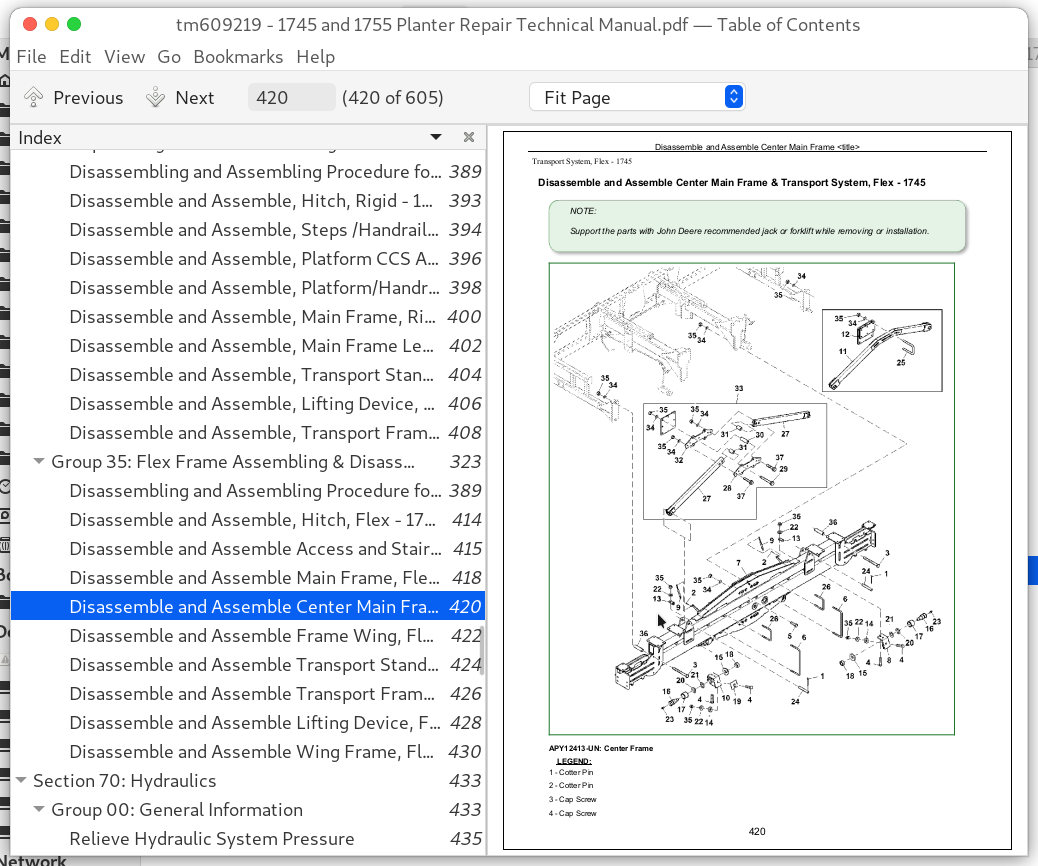
Disassemble and Assemble Center Main Frame Disassemble and Assemble Center Main Frame & Transport System, Flex - 1745{pgNO}323 Transport System, Flex - 1745................420
Disassemble and Assemble Frame Wing, Flex - 1745................422
Disassemble and Assemble Transport Stand, Flex - 1745................424
Disassemble and Assemble Transport Frame, Hitch, Flex - 1745................426
Disassemble and Assemble Lifting Device, Frame, Flex - 1745................428
Disassemble and Assemble Wing Frame, Flex - 1745................430
Section 70: Hydraulics................433
Group 00: General Information................433
Relieve Hydraulic System Pressure................435
Group 05: Motors................433
Other Material................534
Specifications................535
Inspect Vacuum Blower Motor................439
Repair Vacuum Blower Motor................440
Inspect Central Commodity System Blower Motor (1745)................446
Remove and Install Central Commodity System Blower Motor (1745)................448
Repair Central Commodity System Blower Motor (1745)................454
Remove and Install Dry Fertilizer Drive Motor................460
Disassemble and Assemble Dry Fertilizer Drive Motor................463
Group 10: Cylinders................433
Remove and Install Frame Lift Cylinder (1745 Planter Only)................479
Remove and Install Frame Pivot Cylinder (1745 Planter Only)................481
Remove and Install Marker Cylinder (1745 Planter Only)................482
Remove and Install Marker Cylinder (1755 Planter)................485
John Deere Hydraulic Cylinder Repair—Use CTM................488
Group 15: Valves................433
Specifications................535
Remove and Install Solenoid Valves................491
Inspect Solenoid Valve Body................493
Remove and Install Cartridge Valves................494
Flow Control Valve................495
Remove and Install Dry Fertilizer Drive Valve Block................497
Disassemble and Assemble Dry Fertilizer Drive Valve Block................498
Group 20: Miscellaneous................433
Remove and Install Hydraulic Oil Cooler................502
Section 80: Fertilizer Systems................504
Group 10: Dry Fertilizer System................504
Drive Shaft Shear Pins—1755................506
Align Transmission Drive and Auger Shafts—1755................507
Clean Dry Fertilizer Hoppers—1755................508
Replace Auger Sections—1755................510
Dry Fertilizer Shafts—1755................513
Remove and Install Fertilizer Hopper—1745................515
Remove and Install Fertilizer Meter—1745................517
Repair Fertilizer Meter—1745................519
Hopper Repair—1745................521
Section 90: Downforce System................522
Group 00: General Information................522
Depressurize Pneumatic Downforce System................526
Adjust and Inspect Pneumatic Downforce................529
Group 05: Pneumatic Downforce................522
Essential or Recommended Tools................591
Other Material................534
Specifications................535
Install Pneumatic Downforce Air Pressure Gauges (1745)................536
Remove and Install Intergrated Pneumatic Downforce Mono Block Control Valve (1745)................538
Disassemble and Assemble Pneumatic Downforce Mono Block Control Valve (1745)................541
Remove and Install Pneumatic Downforce Mono Block Control Valve Poppet (1745)................543
Remove and Install Pneumatic Downforce Stack Block Control Valve (1745)................554
Disassemble and Assemble Pneumatic Downforce Stack Block Control Valve (1745)................557
Disassemble and Assemble Pneumatic Downforce Stack Block Valve Manifold Segment (1745)................560
Remove and Install Pneumatic Downforce Air Reservoir (1745)................563
Pneumatic Downforce Air Compressor—Exploded View (1745)................564
Frame Mounted Pneumatic Downforce Air Compressor—Exploded View................566
Remove and Install Pneumatic Downforce Air Compressor................568
Remove and Install Air Compressor Filter................571
Remove and Install Air Compressor Isolators................573
Remove and Install Pneumatic Downforce Air Compressor (1755)................574
Remove and Install Air Compressor Filter (1755)................577
Group 10: Heavy Duty Adjustable Mechanical Downforce System................522
Specification................579
Remove and Install Heavy-Duty Downforce Spring Assembly................580
Repair Heavy-Duty Downforce Spring Assembly (Regular Parallel Arms)................583
Repair Heavy-Duty Downforce Spring Assembly (Long Parallel Arms)................585
Group 15: Non-Adjustable Single Spring Downforce System................522
Remove and Install Downforce Spring................588
Section 100: Miscellaneous................589
Group 05: Polyethylene Tank Repair................116
Essential or Recommended Tools................591
Repair Polyethylene Plastic................592
Install RIVNUT Threaded Inserts................598
Section 199: Dealer Fabricated Tools................601
Group 05: Dealer Fabricated Tools................601
DFAXT1—Set Screw Wrench................603
John Deere 1745 and 1755 Planters Frame Repair Service Manual (TM609219)
![]()