
John Deere 1775NT 16-Row Planter with Display-Based Frame Control Diagnosis and Tests Service Technical Manual (TM144919)
Complete Diagnosis & Tests Technical Manual with electrical wiring diagrams for John Deere 1775NT 16-Row Planter with Display-Based Frame Control, with workshop information to maintain, diagnose, and rebuild like professional mechanics.
John Deere 1775NT 16-Row Planter with Display-Based Frame Control workshop Diagnosis & Tests technical manual includes:
* Numbered table of contents easy to use so that you can find the information you need fast.
* Detailed sub-steps expand on repair procedure information
* Numbered instructions guide you through every repair procedure step by step.
* Troubleshooting and electrical service procedures are combined with detailed wiring diagrams for ease of use.
* Notes, cautions and warnings throughout each chapter pinpoint critical information.
* Bold figure number help you quickly match illustrations with instructions.
* Detailed illustrations, drawings and photos guide you through every procedure.
* Enlarged inset helps you identify and examine parts in detail.
tm144919 - 1775NT 16-Row Planter with Display-Based Frame Control Diagnostic Technical Manual Technical Manual.pdf
tm144919 - 1775NT 16-Row Planter with Display-Based Frame Control Diagnostic Technical Manual Technical Manual.epub
PRODUCT DETAILS:
Total Pages: 2,435 pages
File Format: PDF/EPUB/MOBI/AZW (PC/Mac/Android/Kindle/iPhone/iPad; bookmarked, ToC, Searchable, Printable)
Language: English
TABLE OF CONTENTS......1
Section 210: General Information......1008
Group 10: Acronym Table......49
Acronym Table......49
Group 5A: How to Use This Manual......44
Information is Available in Sections, Groups and Subgroups......52
Group 5B: Safety......44
Work In Ventilated Area......54
Recognize Safety Information......55
Avoid Backover Accidents......56
Prevent Machine Runaway......57
Avoid Contact with Agricultural Chemicals......58
Clean Vehicle of Hazardous Pesticides......60
Use a Safety Chain......61
Work in Clean Area......62
Decommissioning — Proper Recycling and Disposal of Fluids and Components......63
Prepare for Emergencies......64
In Case of Fire......65
Use Safety Lights and Devices......66
Avoid High-Pressure Fluids......67
Use Proper Lifting Equipment......68
Illuminate Work Area Safely......69
Live With Safety......70
Support Machine Properly......71
Freeing a Mired Machine......72
Protect Against Noise......73
Remove Paint Before Welding or Heating......74
Park Machine Safely......75
Prevent Acid Burns......76
Follow Safety Instructions......78
Use Proper Tools......79
Keep Riders Off Machine......80
Service Tires Safely......81
Stay Clear of Rotating Drivelines......82
Construct Dealer-Made Tools Safely......83
Practice Safe Maintenance......84
Understand Signal Words......86
Replace Safety Signs......87
Prevent Battery Explosions......88
Protect Against High Pressure Spray......89
Avoid Heating Near Pressurized Fluid Lines......90
Tow Loads Safely......91
Transport Towed Equipment at Safe Speeds......92
Observe Maximum Transport Speed......94
Wear Protective Clothing......95
Precautions for Welding......96
Handle Agricultural Chemicals Safely......98
Service and Operate Chemical Sprayers Safely......100
Relieve Hydraulic Pressure Safely......102
Use Steps and Handholds Correctly......103
Group 5C: Lubricants......45
Grease......105
Gear Oil......106
Alternative and Synthetic Lubricants......107
Lubricant Storage......108
Group 5D: Recommended Tools for Diagnostics......45
Recommended Tools......111
Group 5E: Diagnostic Philosophy......45
Basic Diagnostic Philosophy......116
Systematic Diagnostic Approach Overview......119
Troubleshooting Unresolved Problems......123
Group 5F: Diagnostic Information for Electrical Components......45
Electrical Designators......125
Visually Inspect Electrical System......126
Group 5G: Diagnostic Information for Hydraulic Components......134
Hydraulic Designators......129
Troubleshooting Tips......130
Visually Inspect Hydraulic System......131
Group 5H: Maintaining Hydraulic Systems and Components......46
Hydraulic Components......134
Oil Storage and Filling......135
Oil Filtration......136
Group 5I: Standard Torque Chart Procedures......46
Unified Inch Bolt and Screw Torque Values......139
Metric Bolt and Screw Torque Values......141
Section 211: Diagnostic Trouble Codes......143
Group 10A: Accessing Diagnostic Trouble Codes......164
Accessing Diagnostic Trouble Codes......164
Group 10B: Closing Wheel Controller (CWC) Codes......143
CWC 001351.14 - Air Supply System......143
CWC 001387.00 - System control disabled......143
CWC 001387.01 - System control disabled......143
CWC 001387.03 - Closing Wheel Control System......143
CWC 001387.04 - Closing Wheel Control System......143
CWC 001387.10 - System control disabled......143
CWC 001387.13 - Closing Wheel Control System......143
CWC 001387.14 - Closing Wheel Control System......143
CWC 001387.16 - Pressure too high on Closing Wheel Group 1......143
CWC 001387.17 - Moderate Leak Detected on Closing Wheel Group 1......143
CWC 001388.00 - System control disabled......143
CWC 001388.01 - System control disabled......143
CWC 001388.03 - Closing Wheel Control System......143
CWC 001388.04 - Closing Wheel Control System......143
CWC 001388.10 - System control disabled......143
CWC 001388.13 - Closing Wheel Control System......143
CWC 001388.14 - Closing Wheel Control System......143
CWC 001388.16 - Pressure too high on Closing Wheel Group 2......143
CWC 001388.17 - Moderate Leak Detected on Closing Wheel Group 2......143
CWC 003509.03 - Sensor Voltage is above Normal......143
CWC 003509.04 - Sensor Voltage is below Normal......143
CWC 517151.01 - Closing Wheel Control System......143
CWC 517151.03 - Closing Wheel Control System......143
CWC 517151.04 - Closing Wheel Control System......143
CWC 517151.05 - Closing Wheel Control System......143
CWC 517151.06 - Closing Wheel Control System......143
CWC 517151.12 - Closing Wheel Control System......143
CWC 517152.03 - Closing Wheel Control System......143
CWC 517152.04 - Closing Wheel Control System......143
CWC 517152.12 - Closing Wheel Control System......144
CWC 517153.01 - Closing Wheel Control System......144
CWC 517153.03 - Closing Wheel Control System......144
CWC 517153.04 - Closing Wheel Control System......144
CWC 517153.05 - Closing Wheel Control System......144
CWC 517153.06 - Closing Wheel Control System......144
CWC 517153.12 - Closing Wheel Control System......144
CWC 517154.03 - Closing Wheel Control System......144
CWC 517154.04 - Closing Wheel Control System......144
CWC 517154.12 - Closing Wheel Control System......144
CWC 517154.31 - Closing Wheel Control System......144
CWC 520463.03 - Closing Wheel Control ECU Power......144
CWC 520463.04 - Closing Wheel Control ECU Power......144
CWC 523218.03 - Valve Power 2 Voltage Above Normal......144
CWC 523218.04 - Closing Wheel Control Valve Power 2......144
CWC 523218.05 - Closing Wheel Control Valve Power 2......144
CWC 523438.02 - EEPROM Checksum Error......144
CWC 523438.14 - EEPROM Out of Bounds Error......144
Group 10C: Electric Power Generation (EPG) Codes......144
EPG 000158.00 - ECU 12 Volt Supply Out of Range High......144
EPG 000158.01 - ECU 12 Volt Supply Out of Range Low......144
EPG 000167.00 - 56 Volt Bus Error......144
EPG 000167.01 - Planter 56 V Bus Too Low for Operation......144
EPG 000167.03 - 56 Volt Bus Voltage Sense Line Issue......144
EPG 000167.17 - Planter 56 V Bus Too Low for Good Performance......144
EPG 000186.01 - PTO Not Engaged or Not Spinning While Engaging Alternator......144
EPG 000444.01 - Depleted High Voltage Battery Bank Detected......144
EPG 000444.03 - Battery Bank Voltage Sense Line Issue......144
EPG 000444.04 - Excessive Battery Bank Discharge Detected......144
EPG 000444.17 - Excessive Usage of Battery Bank During Planting Detected......144
EPG 000444.18 - Low High Voltage Battery Bank Detected......144
EPG 000589.00 - Planter Power Generation Alternator Over Speed Detected......144
EPG 001762.00 - Hydraulic Pressure Sensor Signal Out of Range High......144
EPG 001762.01 - Hydraulic Pressure Sensor Signal Out of Range Low......145
EPG 001762.05 - Missing Hydraulic Pressure Sensor Signal......145
EPG 001762.07 - Hydraulic Pressure Not Detected......145
EPG 002197.08 - Seed Monitor Online but Not Responding to CAN Messages......145
EPG 002197.09 - Seed Monitor Controller is Offline......145
EPG 002197.19 - External User Command Synchronization Error Detected......145
EPG 002634.05 - Battery Contactor Failed to Close......145
EPG 002634.06 - Battery Contactor Failed to Open......145
EPG 003380.00 - Tractor Voltage Supply is High......145
EPG 003380.01 - Alternator Excitation Voltage Low......145
EPG 003380.17 - Alternator Excitation Voltage Low......145
EPG 516207.03 - 56 Volt Alternator Relay......145
EPG 516207.05 - 56 Volt Alternator Relay......145
EPG 516207.06 - 56 Volt Alternator Relay......145
EPG 516207.16 - 56 Volt Alternator Relay......145
EPG 516207.17 - 56 Volt Alternator Relay......145
EPG 516207.18 - 56 Volt Alternator Relay......145
EPG 517131.00 - PTO Power Generation......145
EPG 517131.01 - PTO Power Generation......145
EPG 517131.15 - PTO Power Generation......145
EPG 517131.16 - PTO Power Generation......145
EPG 520440.05 - Battery Contactor Open Circuit Fault Detected......145
EPG 520440.06 - Battery Contactor Short Circuit Fault Detected......145
EPG 520440.07 - Battery Energy Storage......145
EPG 521065.00 - 56 V Load Current Sensor Outside of Expected Operation Range......145
EPG 521065.01 - 56 V Load Current Sensor Zero Value Out of Range......145
EPG 521065.02 - 56 V Load Current Sensor Signal Erratic......145
EPG 521065.05 - 56 V Load Current Sensor Signal Missing......145
EPG 521065.10 - High Voltage Load Current Sensor Installed Backwards......145
EPG 521983.00 - ELX 12 Volt Supply Out of Range High......145
EPG 521983.01 - ELX 12 Volt Supply Out of Range Low......145
EPG 523652.07 - 56 V Load Current Sensor Harness Issue......145
EPG 524010.03 - Flow Control Valve HSD Short to Battery......145
EPG 524010.04 - Valve Power Voltage Below Minimum Voltage Required......146
EPG 524010.06 - Flow Control Valve HSD Short to Ground......146
EPG 524010.16 - Flow Control Valve LSD Short to Ground......146
EPG 524010.17 - Flow Control Valve LSD Open Circuit......146
EPG 524010.18 - Flow Control Valve LSD Short to Battery......146
EPG 524039.00 - Power Generation Hydraulic Motor Over Speed Detected......146
EPG 524039.01 - Power Generation Hydraulic Motor Speed Signal Missing......146
EPG 524039.11 - Hydraulic Motor Failed to Reach Soft Start Exit Conditions......146
EPG 524039.16 - Power Generation Hydraulic Motor Spinning Uncommanded......146
EPG 524039.18 - Power Generation Hydraulic Motor Unable to Achieve Target Speed......146
Group 10D: Inertial Measurement Unit (IMU) Codes......146
IMU 520870.02 - EEPROM Checksum Error......146
IMU 521396.12 - Gyroscope Sensor......146
Group 10E: JDLink (JDL) Codes......146
JDLink Diagnostic Trouble Codes......284
Group 10J: Blockage Controller (LBC) Codes......146
LBC 517488.03 - Voltage Above Normal, or Shorted to High Source......146
LBC 517488.04 - Voltage Below Normal, or Shorted to Low Source......146
LBC 517488.12 - Bad Intelligent Device or Component......146
LBC 517489.03 - Voltage Above Normal, or Shorted to High Source......146
LBC 517489.04 - Voltage Below Normal, or Shorted to Low Source......146
LBC 517489.12 - Bad Intelligent Device or Component......146
LBC 517490.03 - Voltage Above Normal, or Shorted to High Source......146
LBC 517490.04 - Voltage Below Normal, or Shorted to Low Source......146
LBC 517490.12 - Bad Intelligent Device or Component......146
LBC 517491.03 - Voltage Above Normal, or Shorted to High Source......146
LBC 517491.04 - Voltage Below Normal, or Shorted to Low Source......146
LBC 517491.12 - Bad Intelligent Device or Component......146
LBC 517492.03 - Voltage Above Normal, or Shorted to High Source......146
LBC 517492.04 - Voltage Below Normal, or Shorted to Low Source......146
LBC 517492.12 - Bad Intelligent Device or Component......146
LBC 517493.03 - Voltage Above Normal, or Shorted to High Source......146
LBC 517493.04 - Voltage Below Normal, or Shorted to Low Source......146
LBC 517493.12 - Bad Intelligent Device or Component......147
LBC 517494.03 - Voltage Above Normal, or Shorted to High Source......147
LBC 517494.04 - Voltage Below Normal, or Shorted to Low Source......147
LBC 517494.12 - Bad Intelligent Device or Component......147
LBC 517495.03 - Voltage Above Normal, or Shorted to High Source......147
LBC 517495.04 - Voltage Below Normal, or Shorted to Low Source......147
LBC 517495.12 - Bad Intelligent Device or Component......147
LBC 517496.03 - Voltage Above Normal, or Shorted to High Source......147
LBC 517496.04 - Voltage Below Normal, or Shorted to Low Source......147
LBC 517496.12 - Bad Intelligent Device or Component......147
LBC 517497.03 - Voltage Above Normal, or Shorted to High Source......147
LBC 517497.04 - Voltage Below Normal, or Shorted to Low Source......147
LBC 517497.12 - Bad Intelligent Device or Component......147
LBC 517498.03 - Voltage Above Normal, or Shorted to High Source......147
LBC 517498.04 - Voltage Below Normal, or Shorted to Low Source......147
LBC 517498.12 - Bad Intelligent Device or Component......147
LBC 517499.03 - Voltage Above Normal, or Shorted to High Source......147
LBC 517499.04 - Voltage Below Normal, or Shorted to Low Source......147
LBC 517499.12 - Bad Intelligent Device or Component......147
LBC 517596.13 - Out of Calibration......147
LBC 521983.03 - Voltage Above Normal, or Shorted to High Source......147
LBC 521983.04 - Voltage Below Normal, or Shorted to Low Source......147
LBC 521983.05 - Current Below Normal or Open Circuit......147
LBC 516992.08 - Abnormal Frequency or Pulse Width or Period......147
LBC 523438.02 - Data Erratic, Intermittent or Incorrect......147
LBC 523438.14 - Special Instructions......147
Group 10K: Master Nozzle Controller (MB1) Codes......147
MB1 000639.14 - Special Instructions......147
MB1 001668.14 - Special Instructions......147
MB1 001669.14 - Special Instructions......147
MB1 003509.03 - Voltage Above Normal, or Shorted to High Source......147
MB1 003509.04 - Voltage Below Normal, or Shorted to Low Source......147
MB1 517068.31 - Not Available or Condition Exists......147
MB1 517471.14 - Special Instructions......148
MB1 517524.03 - Voltage Above Normal, or Shorted to High Source......148
MB1 517524.04 - Voltage Below Normal, or Shorted to Low Source......148
MB1 517524.12 - Bad Intelligent Device or Component......148
MB1 517560.31 - Not Available or Condition Exists......148
MB1 517570.11 - Root Cause Not Known......148
MB1 517596.13 - Out of Calibration......148
MB1 523438.02 - Data Erratic, Intermittent or Incorrect......148
MB1 523438.14 - Special Instructions......148
MB1 000639.12 - Bad Intelligent Device or Component......148
MB1 001668.12 - Bad Intelligent Device or Component......148
MB1 001669.12 - Bad Intelligent Device or Component......148
Group 10F: Meter Master Controller (MMC) Codes......148
MMC 000046.03 - Air Supply System......148
MMC 000046.06 - Air Supply System......148
MMC 000046.13 - Air Supply System......148
MMC 000046.14 - Air Supply System......148
MMC 000084.09 - Wheel Speed Not Detected On CAN Bus......148
MMC 000444.04 - Battery Potential (Voltage) / Power Input 2 Low Voltage......148
MMC 000609.02 - The following Row Unit Controllers are not responding to CAN bus commands......148
MMC 000609.12 - The Following Row Unit Controllers are Offline......148
MMC 000628.02 - MMC EOL Data Revision Mismatch......148
MMC 000639.12 - CAN Bus 1 Communication System......148
MMC 000639.14 - CAN Bus 1 Communication System......148
MMC 000705.03 - These Rows Have a Downforce Sensor Error......148
MMC 000705.04 - These Rows Have a Downforce Sensor Error......148
MMC 000705.13 - Gauge Wheel Downforce Sensor Problem......148
MMC 000705.14 - Gauge Wheel and Vacuum Sensor Configuration is Reset......148
MMC 000838.02 - These Row Unit Controllers Have an Addressing Error......148
MMC 000838.03 - These Row Unit Controllers Have an Addressing Error......148
MMC 000838.04 - These Row Unit Controllers Have an Addressing Error......148
MMC 001231.12 - CAN Bus 2 Communication System......148
MMC 001231.14 - CAN Bus 2 Communication System......149
MMC 001235.12 - CAN Bus 3 Communication System......149
MMC 001235.14 - CAN Bus 3 Communication System......149
MMC 001351.03 - Air Supply System......149
MMC 001351.04 - Air Supply System......149
MMC 001351.06 - Air Supply System......149
MMC 001351.14 - Compressor Motor Time Limit Exceeded......149
MMC 001351.16 - Air Supply System......149
MMC 001351.17 - Air Supply System......149
MMC 001351.18 - Air Supply System......149
MMC 001859.09 - Radar Speed Not Detected On CAN Bus......149
MMC 001859.10 - Ground Speed and Tractor Speed Conflict......149
MMC 003132.00 - Fertilizer Pressure Sensor 1 High......149
MMC 003132.03 - Fertilizer Pressure Sensor 1 Short......149
MMC 003132.06 - Fertilizer Pressure Sensor 1 Short......149
MMC 003132.13 - Fertilizer Pressure Sensor 1 Calibration Error......149
MMC 003132.14 - Fertilizer Pressure Sensor 1 Calibration Error......149
MMC 003509.03 - 5 Volt Sensor Supply Voltage High......149
MMC 003509.04 - 5 Volt Sensor Supply Voltage Low......149
MMC 003510.03 - These Row Unit Controllers Have a Sensor Supply Error......149
MMC 003510.04 - These Row Unit Controllers Have a Sensor Supply Error......149
MMC 003510.05 - 5 Volt Sensor Supply Current Low......149
MMC 003510.06 - 5 Volt Sensor Supply Current High......149
MMC 005109.02 - CAN Bus Communication System Problem......149
MMC 005109.12 - CAN Bus Communication System Problem......149
MMC 005109.14 - CAN Bus Communication System Problem......149
MMC 005121.02 - CAN Bus 1 Communication System......149
MMC 005347.12 - These Rows Have an Accelerometer Error......149
MMC 516249.03 - These Row Unit Controllers Have a 3.3 Volt Bus Error......149
MMC 516249.04 - These Row Unit Controllers Have a 3.3 Volt Bus Error......149
MMC 516781.03 - Hydraulic Pressure Problem......149
MMC 516781.04 - Hydraulic Pressure Problem......149
MMC 516781.12 - Hydraulic Pressure Problem......149
MMC 516781.17 - Low Hydraulic Supply Pressure on the Following Rows......150
MMC 517156.01 - Hydraulic Downforce System Issue on the Following Rows......150
MMC 517156.03 - Row Unit Downforce......150
MMC 517156.04 - Row Unit Downforce......150
MMC 517156.12 - Row Unit Downforce......150
MMC 517156.15 - Hydraulic Downforce System Issue on the Following Rows......150
MMC 517156.17 - Hydraulic Downforce System Issue on the Following Rows......150
MMC 517157.01 - Row Unit Downforce......150
MMC 517157.03 - Row Unit Downforce......150
MMC 517157.04 - Row Unit Downforce......150
MMC 517157.05 - Row Unit Downforce......150
MMC 517157.06 - Row Unit Downforce......150
MMC 520462.03 - These Row Unit Controllers Have a 56 Volt Bus Error......150
MMC 520462.04 - These Row Unit Controllers Have a 56 Volt Bus Error......150
MMC 520463.03 - These Row Unit Controllers Have a 12 Volt Bus Error......150
MMC 520463.04 - These Row Unit Controllers Have a 12 Volt Bus Error......150
MMC 520724.31 - Seed Bin 1 is Almost Empty......150
MMC 520725.31 - Seed Bin 2 is Almost Empty......150
MMC 520728.31 - Seed Bin 3 is Almost Empty......150
MMC 520970.02 - Seed Metering System Issue on the Following Rows......150
MMC 520970.03 - Seed Metering System Issue on the Following Rows......150
MMC 520970.04 - Seed Metering System Issue on the Following Rows......150
MMC 520970.05 - Seed Metering System Issue on the Following Rows......150
MMC 520970.06 - Seed Metering System Issue on the Following Rows......150
MMC 520970.07 - Meter Jam on the Following Rows......150
MMC 520970.08 - These Row Unit Controllers Have an Internal Communication Error......150
MMC 520970.12 - These Row Unit Controllers Have a Meter Motor Alignment Error......150
MMC 520970.16 - Seed Metering System Issue on the Following Rows......150
MMC 520970.18 - Seed Metering System Issue on the Following Rows......150
MMC 520973.02 - Seed Delivery System Issue on the Following Rows......150
MMC 520973.03 - Seed Delivery System Issue on the Following Rows......150
MMC 520973.04 - Seed Delivery System Issue on the Following Rows......150
MMC 520973.05 - Seed Delivery System Issue on the Following Rows......150
MMC 520973.06 - Seed Delivery System Issue on the Following Rows......151
MMC 520973.08 - These Row Unit Controllers Have an Internal Communication Error......151
MMC 520973.12 - These Row Unit Controllers Have a Brush Motor Alignment Error......151
MMC 520973.16 - Seed Delivery System Issue on the Following Rows......151
MMC 520973.18 - Seed Delivery System Issue on the Following Rows......151
MMC 520975.02 - The Following Rows Have a Seed Sensor or Harness Issue......151
MMC 520975.03 - The Following Rows Have a Seed Sensor or Harness Issue......151
MMC 520975.04 - The Following Rows Have a Seed Sensor or Harness Issue......151
MMC 520975.05 - The Following Rows Have a Seed Sensor or Harness Issue......151
MMC 520975.06 - The Following Rows Have a Seed Sensor or Harness Issue......151
MMC 520975.07 - The Following Rows Have a Seed Sensor or Harness Issue......151
MMC 520975.16 - The Following Rows Have a Seed Sensor or Harness Issue......151
MMC 521037.03 - These Rows Have a Vacuum Sensor Error......151
MMC 521037.04 - These Rows Have a Vacuum Sensor Error......151
MMC 521037.13 - Seed Vacuum Sensor Problem......151
MMC 521087.03 - Pneumatic Downforce System Group 2......151
MMC 521087.04 - Pneumatic Downforce System Group 2......151
MMC 521087.06 - Pneumatic Downforce System Group 2......151
MMC 521087.16 - Pneumatic Downforce System Group 2......151
MMC 521087.17 - Pneumatic Downforce System Group 2......151
MMC 521087.18 - Pneumatic Downforce System Group 2......151
MMC 521092.03 - Pneumatic Downforce System Group 2......151
MMC 521092.04 - Pneumatic Downforce System Group 2......151
MMC 521092.06 - Pneumatic Downforce System Group 2......151
MMC 521092.16 - Pneumatic Downforce System Group 2......151
MMC 521092.17 - Pneumatic Downforce System Group 2......151
MMC 521092.18 - Pneumatic Downforce System Group 2......151
MMC 521130.03 - Pneumatic Downforce System Group 2......151
MMC 521130.06 - Pneumatic Downforce System Group 2......151
MMC 521130.13 - Pneumatic Downforce System Group 2......151
MMC 521130.14 - Pneumatic Downforce System Group 2......151
MMC 521260.03 - These Row Unit Controllers Have a 13 Volt Bus Error......151
MMC 521260.04 - These Row Unit Controllers Have a 13 Volt Bus Error......151
MMC 521529.00 - Fertilizer Pressure Sensor 2......152
MMC 521529.03 - Fertilizer Pressure Sensor 2......152
MMC 521529.06 - Fertilizer Pressure Sensor 2......152
MMC 521529.13 - Fertilizer Pressure Sensor 2......152
MMC 521529.14 - Fertilizer Pressure Sensor 2......152
MMC 521939.03 - Pneumatic Downforce System Group 1......152
MMC 521939.06 - Pneumatic Downforce System Group 1......152
MMC 521939.06 - Pneumatic Downforce System Group 1......152
MMC 521939.13 - Pneumatic Downforce System Group 1......152
MMC 521939.14 - Pneumatic Downforce System Group 1......152
MMC 521940.03 - Pneumatic Downforce System Group 1......152
MMC 521940.04 - Pneumatic Downforce System Group 1......152
MMC 521940.06 - Pneumatic Downforce System Group 1......152
MMC 521940.16 - Pneumatic Downforce System Group 1......152
MMC 521940.17 - Pneumatic Downforce System Group 1......152
MMC 521940.18 - Pneumatic Downforce System Group 1......152
MMC 521941.03 - Pneumatic Downforce System Group 1......152
MMC 521941.04 - Pneumatic Downforce System Group 1......152
MMC 521941.06 - Pneumatic Downforce System Group 1......152
MMC 521941.16 - Pneumatic Downforce System Group 1......152
MMC 521941.17 - Pneumatic Downforce System Group 1......152
MMC 521941.18 - Pneumatic Downforce System Group 1......152
MMC 522260.02 - Planter Wheel Motion Sensor Speed Abnormal Compared to Tractor Speed......152
MMC 522260.10 - Motion Sensor Responding When No Active Tractor Speed......152
MMC 522941.11 - Selected Ground Speed Source is Wheel......152
MMC 522941.14 - Selected Ground Speed Source is Manual......152
MMC 522941.31 - Ground Based Speed Source is Not Available in AUTO Speed Mode......152
MMC 523194.14 - The Following Rows are not Planting Due to Section Control......152
MMC 523194.31 - The Following Rows are not Planting Near Target Rate......152
MMC 523216.03 - Electrical System......152
MMC 523216.04 - Electrical System......152
MMC 523216.05 - Electrical System......152
MMC 523217.03 - Electrical System......152
MMC 523217.04 - Electrical System......153
MMC 523217.05 - Electrical System......153
MMC 523218.03 - Electrical System......153
MMC 523218.04 - Electrical System......153
MMC 523218.05 - Electrical System......153
MMC 523219.03 - Electrical System......153
MMC 523219.04 - Electrical System......153
MMC 523219.05 - Electrical System......153
MMC 523319.03 - Electrical System......153
MMC 523319.04 - ECU Power Voltage Low......153
MMC 523328.03 - Height Sensor Voltage High......153
MMC 523328.04 - Height Sensor Below Normal Operating Range......153
MMC 523328.11 - Height Sensor Not Calibrated......153
MMC 523328.14 - Height Sensor Mismatch......153
MMC 523328.31 - Height Sensor Mismatch......153
MMC 523418.31 - Tank Almost Empty......153
MMC 523438.02 - EEPROM Checksum Error......153
MMC 523438.12 - These Row Unit Controllers Have an EEPROM Checksum Error......153
MMC 523438.14 - EEPROM Out of Bounds Error......153
MMC 524054.14 - The Acres to Empty Counter on the Planter Totals Page Has Reached Zero......153
Group 10L: Master Nozzle Controller (MNA) Codes......153
MNA 000158.04 - Voltage Below Normal, or Shorted to Low Source......153
MNA 000628.12 - Bad Intelligent Device or Component......153
MNA 000639.14 - Special Instructions......153
MNA 001668.02 - Data Erratic, Intermittent or Incorrect......153
MNA 001668.09 - Abnormal Update Rate......153
MNA 001668.14 - Special Instructions......153
MNA 001669.02 - Data Erratic, Intermittent or Incorrect......153
MNA 001669.09 - Abnormal Update Rate......153
MNA 001669.14 - Special Instructions......153
MNA 001670.02 - Data Erratic, Intermittent or Incorrect......153
MNA 001670.09 - Abnormal Update Rate......153
MNA 001670.14 - Special Instructions......153
MNA 001671.02 - Data Erratic, Intermittent or Incorrect......154
MNA 001671.09 - Abnormal Update Rate......154
MNA 001671.14 - Special Instructions......154
MNA 520349.05 - Current Below Normal or Open Circuit......154
MNA 520349.06 - Current Above Normal or Grounded Circuit......154
MNA 520349.07 - Mechanical System Not Responding or Out of Adjustment......154
MNA 520349.16 - Data Valid but Above Normal Operating Range - Moderately Severe Level......154
MNA 520349.18 - Data Valid but Below Normal Operating Range - Moderately Severe Level......154
MNA 520870.02 - Data Erratic, Intermittent or Incorrect......154
MNA 520871.02 - Data Erratic, Intermittent or Incorrect......154
MNA 520872.02 - Data Erratic, Intermittent or Incorrect......154
MNA 521710.05 - Current Below Normal or Open Circuit......154
MNA 521710.06 - Current Above Normal or Grounded Circuit......154
MNA 521710.31 - Not Available or Condition Exists......154
MNA 521711.05 - Current Below Normal or Open Circuit......154
MNA 521711.06 - Current Above Normal or Grounded Circuit......154
MNA 521711.31 - Not Available or Condition Exists......154
MNA 522289.05 - Current Below Normal or Open Circuit......154
Section 212: Observable Symptoms and System Diagnostics......937
Group 10: Observable Symptoms......937
56 Volt Power Observable Symptoms......940
Auxiliary Hydraulics Observable Symptoms......941
Auxiliary Power Observable Symptoms......942
CAN Bus Observable Symptoms......943
CCS Agitator Observable Symptoms......946
CCS Blower Observable Symptoms......947
CCS Tank Low Warning Observable Symptoms......949
Curve Compensation Observable Symptoms......950
Drawbar Hitch Observable Symptoms......951
Easy Fold Observable Symptoms......959
ECU Power Observable Symptoms......954
Enhanced Monitoring Observable Symptoms......955
Fertilizer Pressure Observable Symptoms......956
Field Lift Observable Symptoms......957
Fold Observable Symptoms......959
Height Observable Symptoms......961
High Current Power Observable Symptoms......962
Hydraulic Downforce Observable Symptoms......964
Implement Receiver Observable Symptoms......965
Lighting - CCS Fill Lights Observable Symptoms......966
Lighting - Transport Lights Observable Symptoms......968
Markers Observable Symptoms......970
Motion Sensor Observable Symptoms......971
Pneumatic Closing Wheels Observable Symptoms......972
Pneumatic Downforce Observable Symptoms......974
Pneumatic Row Cleaners Observable Symptoms......976
Power Generation - Planter Observable Symptoms......978
Power Generation - Tractor Observable Symptoms......980
Rate Controller Observable Symptoms......981
Row Unit Observable Symptoms......983
Seed Monitoring Observable Symptoms......986
SeedStar Mobile Observable Symptoms......987
Service ADVISOR Remote Observable Symptoms......989
Transport Lift Observable Symptoms......990
Vacuum Observable Symptoms......992
Section 240: Electrical......994
Group 05: General Information......1008
General Information......1008
Intermittent Fault Diagnostics......1018
Circuit Load Test......1019
Group 20: Theory of Operation......994
56 Volt Power Electrical Theory of Operation......1023
Auxiliary Hydraulics Electrical Theory of Operation......1024
Auxiliary Power Electrical Theory of Operation......1025
CAN Bus Electrical Theory of Operation......1026
CCS Agitator Electrical Theory of Operation......1027
CCS Blower Electrical Theory of Operation......1028
CCS Tank Low Warning Electrical Theory of Operation......1029
Curve Compensation Electrical Theory of Operation......1030
Drawbar Hitch Electrical Theory of Operation......1031
Easy Fold Electrical Theory of Operation......1042
ECU Power Electrical Theory of Operation......1034
Enhanced Monitoring Electrical Theory of Operation......1035
ExactRate Nozzle Control Theory of Operation......1036
Fertilizer Pressure Electrical Theory of Operation......1040
Field Lift Electrical Theory of Operation......1041
Fold Electrical Theory of Operation......1042
Height Electrical Theory of Operation......1043
High Current Power Electrical Theory of Operation......1044
Hydraulic Downforce Electrical Theory of Operation......1045
Implement Receiver Electrical Theory of Operation......1047
Lighting - CCS Fill Lights Electrical Theory of Operation......1048
Lighting - Transport Lights (EU) Electrical Theory of Operation......1049
Lighting - Transport Lights (NA) Electrical Theory of Operation......1050
Markers Electrical Theory of Operation......1052
Motion Sensor Electrical Theory of Operation......1053
Pneumatic Closing Wheels Electrical Theory of Operation......1054
Pneumatic Downforce Electrical Theory of Operation......1056
Pneumatic Row Cleaners Electrical Theory of Operation......1058
Power Generation - Planter Electrical Theory of Operation......1060
Power Generation - Tractor Electrical Theory of Operation......1062
Rate Controller Electrical Theory of Operation......1064
Row Unit Electrical Theory of Operation......1065
Seed Monitoring Electrical Theory of Operation......1069
SeedStar Mobile Electrical Theory of Operation......1070
Service ADVISOR Remote Electrical Theory of Operation......1071
Transport Lift Electrical Theory of Operation......1072
Vacuum Electrical Theory of Operation......1073
Group 30: Schematics......995
56 Volt Power Electrical Schematic......1077
Auxiliary Hydraulics Electrical Schematic......1079
Auxiliary Power Electrical Schematic......1080
CAN Bus - Implement CAN Electrical Schematic......1083
CAN Bus - Subnets Electrical Schematic......1085
CCS Agitator Electrical Schematic......1087
CCS Blower Electrical Schematic......1089
CCS Tank Low Warning Electrical Schematic......1090
Drawbar Hitch Electrical Schematic......1091
ECU Power Electrical Schematic......1092
Enhanced Monitoring Electrical Schematic......1094
Fertilizer 12V Power and Ground Electrical Schematic......1095
Fertilizer CAN Bus Electrical Schematics......1096
Fertilizer ECU Power and Ground Electrical Schematic......1098
Fertilizer Nozzles Electrical Schematic......1099
Fertilizer Pressure Sensors Electrical Schematic......1100
Fertilizer Pump Sensors Electrical Schematic......1101
Fertilizer Disconnects Electrical Schematic......1102
Fertilizer Pressure Electrical Schematic......1103
Field Lift Electrical Schematic......1104
Fold Electrical Schematic......1105
Height Electrical Schematic......1106
High Current Power Electrical Schematic......1107
Hydraulic Downforce Electrical Schematic......1109
Implement Receiver Electrical Schematic......1111
Lighting - CCS Fill Lights Electrical Schematic......1112
Lighting - Transport Lights Identification......1113
Lighting - Transport Lights (EU) Electrical Schematic......1114
Lighting - Transport Lights (NA) Electrical Schematic......1115
Markers Electrical Schematic......1116
Motion Sensor Electrical Schematic......1117
Pneumatic Closing Wheels Electrical Schematic......1118
Pneumatic Downforce Electrical Schematic......1119
Pneumatic Row Cleaners Electrical Schematic......1120
Power Generation - Planter Electrical Schematic......1121
Power Generation - Tractor Electrical Schematic......1123
Rate Controller Electrical Schematic......1125
Row Unit Electrical Schematic......1127
Seed Monitoring Electrical Schematic......1130
SeedStar Mobile Electrical Schematic......1131
Service ADVISOR Remote Electrical Schematic......1133
Transport Lift Electrical Schematic......1135
Vacuum Electrical Schematic......1136
Group 50: Diagnostics......996
56 Volt Power Electrical Diagnostic......1142
Auxiliary Hydraulics Electrical Diagnostic......1147
Auxiliary Power Electrical Diagnostic......1149
CAN Bus Electrical Diagnostic......1157
CCS Agitator Electrical Diagnostic......1162
CCS Blower Electrical Diagnostic......1166
CCS Tank Low Warning Electrical Diagnostic......1170
Disconnects Electrical Diagnostic......1173
ECU Power Electrical Diagnostic......1178
ExactRate Nozzle — Electrical Diagnostic......1181
Fertilizer Pressure Electrical Diagnostic......1196
Field Lift Electrical Diagnostic......1199
Fold Electrical Diagnostic......1205
Fold Sensor Electrical Diagnostic......1211
Height Electrical Diagnostic......1214
High Current Power Electrical Diagnostic......1218
Hydraulic Downforce Electrical Diagnostic......1223
Implement Receiver Electrical Diagnostic......1228
Lighting - Transport Lights (EU) Electrical Diagnostic......1234
Lighting - Transport Lights (NA) Electrical Diagnostic......1243
Markers Electrical Diagnostic......1256
Motion Sensor Electrical Diagnostic......1262
Pneumatic Closing Wheels Electrical Diagnostic......1265
Pneumatic Downforce Electrical Diagnostic......1276
Pneumatic Row Cleaners Electrical Diagnostic......1285
Power Generation - Planter Electrical Diagnostic......1299
Power Generation - Tractor Electrical Diagnostic......1311
Rate Controller Electrical Diagnostic......1324
Transport Lift Electrical Diagnostic......1335
Section 245: Electronic Control Units......1341
Group 10A: Accessing Diagnostic Addresses......1348
Accessing Diagnostic Addresses......1348
Group 10B: Diagnostic Addresses by Control Unit......1341
Closing Wheel Controller (CWC) Addresses......1366
Electrical Power Generation (EPG) Addresses......1378
Inertial Measurement Unit (IMU) Addresses......1391
JDLink (JDL) Addresses......1393
Meter Master Controller (MMC) Addresses......1400
Planter Assist Controller (PAC) Addresses......1421
Row Cleaner Controller (RCC) Addresses......1434
Row Unit Controller (RUC) Addresses......1444
Wireless Data Server (WDS) Addresses......1454
Spray Rate Controller (SRC) Addresses......1455
Nozzle Controller (NZC) Addresses......1462
Master Nozzle Controller (MNA) Addresses......1467
Master Nozzle Controller (MB1) Addresses......1471
Liquid Flow Detection Controller (LBC) Addresses......1475
Group 50: Diagnostic Tests and Adjustments......1341
Closing Wheel Controller (CWC) Test......1481
Electrical Power Generation Control Unit (EPG) Test......1485
Modular Telematics Gateway Control Unit (MTG) Test......1489
Planter Main Controller (PMC) Test......1497
Row Unit Controller (RUC) Test......1504
Wireless Data Server (WDS) Test......1511
Section 249: Electrical Connectors......1517
Group 40A: Electrical Assemblies......1517
XA0001 — Liquid Flow Control Unit 1 Connector......1528
XA0002 — Liquid Flow Control Unit 2 Connector......1531
XA4 — Flasher Module Connector......1534
XA8-1 — Rate Controller J1 Connector......1536
XA8-2 — Rate Controller J2 Connector......1539
XA8-3 — Rate Controller J3 Connector......1543
XA9 — Implement Receiver Connector......1547
XA10 — Implement CAN Bus Secondary Terminator Connector......1549
XA12-1 — Planter Main Controller J1 Connector......1551
XA12-2 — Planter Main Controller J2 Connector......1555
XA12-3 — Planter Main Controller J3 Connector......1559
XA12-4 — Planter Main Controller J4 Connector......1563
XA15 — Left CAN Bus Primary Terminator Connector......1565
XA16 — Left CAN Bus Secondary Terminator Connector......1567
XA17 — CAN Bus Diagnostic Plug......1569
XA18 — Right CAN Bus Primary Terminator Connector......1571
XA19 — Right CAN Bus Secondary Terminator Connector......1573
XA50 — Electrical Power Generation Control Unit Connector......1575
XA51 — Battery Box Connector......1579
XA53-1 — Fuse Box SSVEC 1 Connector......1581
XA53-2 — Fuse Box SSVEC 2 Connector......1583
XA53-3 — Fuse Box 1 Connector......1585
XA53-4 — Fuse Box 2 Connector......1587
XA70-1 — Closing Wheel Controller J1 Connector......1589
XA70-2 — Closing Wheel Controller J2 Connector......1593
XA90 — Wireless Data Server Connector......1597
XA90-2 — SeedStar Mobile Antenna Connector......1599
XA99 — Modular Telematics Gateway Control Unit Connector......1601
XA99-C — SAR Antenna Cell Connector......1605
XA99-G — SAR Antenna GPS Connector......1607
XA101 - XA116 — Row Unit Controller Connectors......1609
XA3001 — LH Sub CAN Bus Terminator 1 Connector......1612
XA3002 — LH Sub CAN Bus Terminator 2 Connector......1613
XA3003 — RH Sub CAN Bus Terminator 1 Connector......1614
XA3004 — RH Sub CAN Bus Terminator 2 Connector......1615
XA3005 — Keypad Connector......1616
XA3010-1 — DC/DC Converter Connector......1617
XA3010-2 — DC/DC Converter Connector......1619
XA4001 - XA40XX — ExactRate Nozzle Connectors......1621
XA5000-1 — Fertilizer Main Control Unit Connector......1622
XA5000-2 — Fertilizer Main Control Unit Connector......1625
XA5000-3 — Fertilizer Main Control Unit Connector......1628
XA5000-4 — Fertilizer Main Control Unit Connector......1631
Group 40B: Sensors......1518
XB1 — Height Sensor Connector......1635
XB2 — Motion Sensor Connector......1637
XB0009 — Flow Meter Sensor Connector......1639
XB21 — Fold Sensor Connector......1641
XB0023 — Pump Speed Sensor Connector......1643
XB26 — Drawbar Hitch Sensor Connector......1645
XB30 — Downforce System Hydraulic Pressure Sensor Connector......1647
XB41 — CCS Pressure Sensor Connector......1649
XB43 — Left Bin Level Sensor Connector......1651
XB44 — Right Bin Level Sensor Connector......1653
XB45 — Front Bin Level Sensor Connector......1655
XB51 — Alternator Motor Pressure Sensor Connector......1657
XB52 — Alternator Motor Speed Sensor Connector......1659
XB55 — Alternator Current Sensor Connector......1661
XB56 — PTO Temperature Sensor Connector......1663
XB61 — Vacuum 1 Pressure Sensor Connector......1665
XB62 — Vacuum 2 Pressure Sensor Connector......1667
XB70-1 — Tank Pressure Sensor Connector......1669
XB71 — Pressure Sensor 1 Connector......1671
XB73 — Pressure Sensor 3 Connector......1673
XB74 — Pressure Sensor 4 Connector......1675
XB0075 — Pump Pressure Sensor Connector......1677
XB75 — Pressure Sensor 5 Connector......1679
XB76 — Pressure Sensor 6 Connector......1681
XB77 — Pressure Sensor 7 Connector......1683
XB81 — Fertilizer Pressure Sensor 1 Connector......1685
XB101 - XB116 — Seed Sensor Connectors......1687
XB401 - XB416 — Gauge Wheel Load Sensor Connectors......1690
XB501 - XB516 — Row Hydraulic Pressure Sensor Connectors......1692
XB1001 - XB10XX — Row Pressure Sensor Connectors......1694
Group 40E: Lights......1519
XE1 — Left Amber Light (NA) Connector......1698
XE2 — Left Red Light (NA) Connector......1700
XE3 — Right Red Light (NA) Connector......1702
XE4 — Right Amber Light (NA) Connector......1704
XE11 — Left Amber Light (EU) Connector......1706
XE12 — Left Red Light (EU) Connector......1707
XE13 — Right Red Light (EU) Connector......1708
XE14 — Right Amber Light (EU) Connector......1709
XE43 — Left Fill Light Connector......1710
XE44 — Right Fill Light Connector......1712
XE45 — Front Fill Light Connector......1714
Group 40F: Fuses......1519
XF23 — 0132 Fuse Connector......1718
XF24 — 0142 Fuse Connector......1720
XF25 — 0152 Fuse Connector......1722
XF26 — 0162 Fuse Connector......1724
XF51 — Planter Battery Fuse Connector......1726
XF55 — Tractor Power Generation Fuse Connector......1728
XF99 — MTG Fuse Connector......1730
XF0122 — IBBC Fuse Connector......1732
XF0160 — DC/DC Ground Fuse 1 Connector......1734
XF0162 — DC/DC Power Fuse 1 Connector......1736
XF0170 — DC/DC Ground Fuse 2 Connector......1738
XF0172 — DC/DC Power Fuse 2 Connector......1740
XF0502 — 56V Inline Fuse Connector......1742
Group 40G: Charging......1520
XG51-N — Planter Battery 1 Negative Connector......1746
XG51-P — Planter Battery 1 Positive Connector......1748
XG52-N — Planter Battery 2 Negative Connector......1750
XG52-P — Planter Battery 2 Positive Connector......1752
XG53-N — Planter Battery 3 Negative Connector......1754
XG53-P — Planter Battery 3 Positive Connector......1756
XG54-N — Planter Battery 4 Negative Connector......1758
XG54-P — Planter Battery 4 Positive Connector......1760
XG55-AG — Alternator Ground Connector......1762
XG55-AP — Alternator Power 1 Connector......1764
XG55-BP — Battery Power Connector......1766
XG55-FG — Alternator Field Ground Connector......1768
XG55-FP — Alternator Field Power Connector......1770
XG55-GD — Ground Distribution Connector......1772
XG57-NEG — Tractor Alternator Negative Connector......1774
XG57-POS — Tractor Alternator Positive Connector......1776
XG57-VE — Tractor Alternator Voltage Sense Connector......1778
XG57-FP — Tractor Alternator Field Power Connector......1780
XG99-N — SAR Battery Negative Connector......1782
XG99-P — SAR Battery Positive Connector......1784
Group 40K: Relays......1520
XK43 — Left Agitator Relay Connector......1788
XK44 — Right Agitator Relay Connector......1790
XK45 — Front Agitator Relay Connector......1792
XK51-A — Battery Contactor Connector A......1794
XK51-B — Battery Contactor Connector B......1796
XK51-C — Battery Contactor Connector C......1798
XK51-D — Battery Contactor Connector D......1800
XK51-CF — Contactor Field Connector......1802
XK55 — Alternator Relay......1804
Group 40M: Motors......1521
XM43-1 — Left Agitator Motor Power Connector......1809
XM43-2 — Left Agitator Motor Ground Connector......1811
XM44-1 — Right Agitator Motor Power Connector......1813
XM44-2 — Right Agitator Motor Ground Connector......1815
XM45-1 — Front Agitator Motor Power Connector......1817
XM45-2 — Front Agitator Motor Ground Connector......1819
XM101-B - XM116-B — BrushBelt Motor Connectors......1821
XM101-M - XM116-M — Meter Motor Connectors......1823
Group 40R: Resistor......1521
XR99 — MTG Resistor Connector......1827
Group 40S: Switches......1521
XS10 — Foot Switch Connector......1831
XS11 — Master Switch Connector......1833
XS17 — Row Switch Connector......1835
XS40 — Fill Light Switch Connector......1837
XS44 — Rear CCS Remote Switch Connector......1839
XS45 — Front CCS Remote Switch Connector......1841
Group 40W: Wiring Harnesses......1521
W0050 — Alternator Harness......1845
W0053 — EPG Harness......1847
W0201 — Left Wing Fertilizer Harness......1849
W0202 — Center Fertilizer Harness......1850
W0203 — Right Wing Fertilizer Harness......1852
W0204 — Pump Control Harness......1853
W0205 — DC-DC Converter Harness......1855
Group 40X: Interconnects......1521
XX1 — Implement CAN Bus Connector......1859
XX2 — Constant Power Harness Interconnect......1861
XX2-B — Implement Guidance Connector......1863
XX3 — Convenience Plug 1......1865
XX5 — Battery Power Interconnect......1867
XX6 — CAN Bus Tether Harness Interconnect......1869
XX11-A — Left Wing A Interconnect......1872
XX11-B — Left Wing B Interconnect......1875
XX13-A — Right Wing A Interconnect......1878
XX13-B — Right Wing B Interconnect......1881
XX15 — Valve Manifold Harness Interconnect......1884
XX16 — Motion Harness Interconnect......1886
XX17 — Row Switch Harness Interconnect......1888
XX19-A — Rate Controller Harness Interconnect A......1890
XX19-B — Rate Controller Harness Interconnect B......1892
XX19-C — Rate Controller Harness Interconnect C......1894
XX20-1 — Lighting and Accessory Outlet (NA)......1897
XX20-2 — Lighting and Accessory Outlet (EU)......1899
XX20-A — Implement CAN Bus Terminator Harness Interconnect A......1901
XX20-B — Implement CAN Bus Terminator Harness Interconnect B......1903
XX22 — Lighting Tether Harness Interconnect......1905
XX24 — Auxiliary Power Interconnect......1907
XX28 — Rear Hitch Interconnect......1909
XX28-1 — Rear Hitch Outlet......1911
XX29-A — Implement Receiver Harness Interconnect A......1913
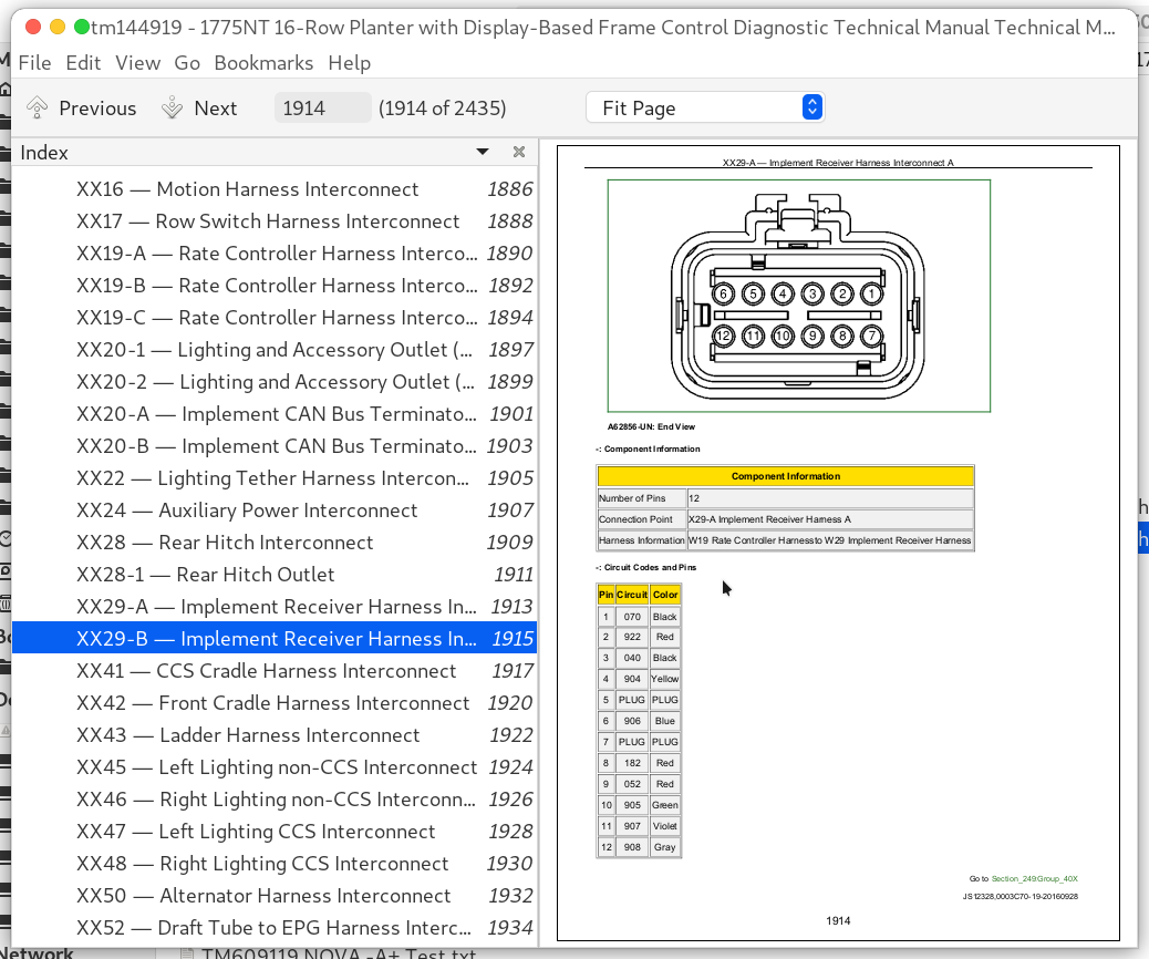
XX29-B — Implement Receiver Harness Interconnect B......1915
XX41 — CCS Cradle Harness Interconnect......1917
XX42 — Front Cradle Harness Interconnect......1920
XX43 — Ladder Harness Interconnect......1922
XX45 — Left Lighting non-CCS Interconnect......1924
XX46 — Right Lighting non-CCS Interconnect......1926
XX47 — Left Lighting CCS Interconnect......1928
XX48 — Right Lighting CCS Interconnect......1930
XX50 — Alternator Harness Interconnect......1932
XX52 — Draft Tube to EPG Harness Interconnect 1......1934
XX53 — Draft Tube to EPG Harness Interconnect 2......1936
XX54 — Hitch to Draft Tube Harness Interconnect 1......1938
XX55 — Hitch to Draft Tube Harness Interconnect 2......1940
XX56 — Temperature Sensor Harness Interconnect......1942
XX57 — Tractor Alternator Harness Interconnect......1944
XX71 — Pneumatic Harness Interconnect......1946
XX72-A — Closing Wheel Harness CAN Interconnect......1949
XX72-B — Closing Wheel Harness Power Interconnect......1951
XX80-LCL — Row Disconnects Interconnect LCL......1953
XX80-RCL — Row Disconnects Interconnect RCL......1955
XX80-S1 — Row Disconnects Interconnect S1......1957
XX80-S2 — Row Disconnects Interconnect S2......1959
XX81 — Fertilizer Pressure Harness 1 Interconnect......1961
XX90 — SeedStar Mobile Harness Interconnect......1963
XX90J — Data Server Jumper Harness Interconnect......1965
XX91 — CAN Bus Jumper Harness Interconnect......1967
XX98 — SAR Power Interconnect......1969
XX99 — MTG Harness Interconnect......1971
XX101 - XX116 — Row Unit Harness Interconnects......1974
XX2002 — ExactRate CAN Bus Interconnect......1976
XX2007 — ExactRate CAN Bus In Interconnect......1978
XX2008 — ExactRate Power In Interconnect......1981
XX2017 — ExactRate CAN Bus Out Interconnect......1983
XX2018 — ExactRate Power Out Interconnect......1986
XX2900 — DC/DC Converter to EPG/Alternator Harness Interconnect......1988
XX3000 — ExactRate Center to Left Wing Harness Interconnect......1990
XX3001 — ExactRate Center to Right Wing Harness Interconnect......1993
XX3002 — ExactRate Center to DC/DC Converter Harness Interconnect......1996
XX3003 — Exact Rate Center to Pump Harness Interconnect......1999
XX3003F — Exact Rate Center to Pump Harness Interconnect......2002
XX3004 — DC/DC Converter to EPG/Alternator Harness Interconnect......2005
Group 40Y: Electronically Actuated Mechanical Devices......1523
XY1 — Center Frame Solenoid Connector......2009
XY2 — Left Wing Solenoid Connector......2011
XY3 — Right Wing Solenoid Connector......2013
XY5 — Left Marker Solenoid Connector......2015
XY6 — Right Marker Solenoid Connector......2017
XY8 — Auxiliary Fold Solenoid Connector......2019
XY9 — Main Fold Solenoid Connector......2021
XY26 — Tongue Lift Solenoid Valve 1......2299
XY0026 — Pump Proportional Valve Connector......2025
XY27 — Tongue Lift Solenoid Valve 2......2300
XY41 — CCS Blower Solenoid Connector......2029
XY51 — Alternator Motor Flow Solenoid Connector......2031
XY70 — Hydraulic Compressor Solenoid Connector......2033
XY71-1 — Fill Solenoid Valve 1 Connector......2035
XY71-2 — Exhaust Solenoid Valve 1 Connector......2037
XY73-1 — Fill Solenoid Valve 3 Connector......2039
XY73-2 — Exhaust Solenoid Valve 3 Connector......2041
XY0074 — Pump Isolation Valve Connector......2043
XY74-1 — Fill Solenoid Valve 4 Connector......2045
XY74-2 — Exhaust Solenoid Valve 4 Connector......2047
XY75-1 — Fill Solenoid Valve 5 Connector......2049
XY75-2 — Exhaust Solenoid Valve 5 Connector......2051
XY76-1 — Fill Solenoid Valve 6 Connector......2053
XY76-2 — Exhaust Solenoid Valve 6 Connector......2055
XY77-1 — Fill Solenoid Valve 7 Connector......2057
XY77-2 — Exhaust Solenoid Valve 7 Connector......2059
XY501 - XY516 — Row Downforce Solenoid Connectors......2061
Section 270: Hydraulics......2063
Group 20: Theory of Operation......2063
Auxiliary Hydraulics Hydraulic Theory of Operation......2066
CCS Blower Hydraulic Theory of Operation......2067
Drawbar Hitch Hydraulic Theory of Operation......2068
Field Lift Hydraulic Theory of Operation......2069
Fold Hydraulic Theory of Operation......2072
Hydraulic Compressor Hydraulic Theory of Operation......2073
Hydraulic Downforce Hydraulic Theory of Operation......2074
Markers Hydraulic Theory of Operation......2077
Power Generation - Planter Hydraulic Theory of Operation......2079
Transport Lift Hydraulic Theory of Operation......2080
Vacuum Hydraulic Theory of Operation......2082
Group 30: Schematics......2063
Auxiliary Hydraulics Hydraulic Schematic......2085
CCS Blower Hydraulic Schematic......2086
Drawbar Hitch Hydraulic Schematic......2087
Fertilizer Pump Hydraulic Schematic......2088
Field Lift Hydraulic Schematic......2089
Fold Hydraulic Schematic......2092
Hydraulic Compressor Hydraulic Schematic......2093
Hydraulic Downforce Hydraulic Schematic......2094
Markers Hydraulic Schematic......2095
Power Generation - Planter Hydraulic Schematic......2097
Transport Lift Hydraulic Schematic......2098
Vacuum Hydraulic Schematic......2100
Group 50: Diagnostics......2063
Auxiliary Hydraulics Hydraulic Diagnostic......2104
CCS Blower Hydraulic Diagnostic......2106
Field Lift Hydraulic Diagnostic......2109
Fold Hydraulic Diagnostic......2115
Hydraulic Compressor Hydraulic Diagnostic......2119
Lift Cylinders Test......2122
Markers Hydraulic Diagnostic......2134
Power Generation - Planter Hydraulic Diagnostic......2138
Transport Lift Hydraulic Diagnostic......2140
Vacuum Hydraulic Diagnostic......2146
Valve Test (IRHD System Only)......2148
Valve Flush Test (IRHD System Only)......2151
Air Purge Test (IRHD System Only)......2154
Accumulator Test (IRHD System Only)......2157
Section 279: Hydraulic Component Information......2160
Group 40A: Accumulator......2160
A70 — Case Drain Accumulator......2165
Group 40B: Sensor or Gauge......2160
B30 — Downforce System Hydraulic Pressure Sensor......2167
B51 — Alternator Motor Pressure Sensor......2168
B501 - B516 — Row Hydraulic Pressure Sensors......2169
Group 40C: Cylinder, Actuator, or Piston......2160
C1 — Left Wing Outside Cylinder......2171
C2 — Left Wing Inside Cylinder......2172
C3 — Left Center Outside Cylinder......2173
C4 — Left Center Inside Cylinder......2174
C5 — Right Center Inside Cylinder......2175
C6 — Right Center Outside Cylinder......2176
C7 — Right Wing Inside Cylinder......2177
C8 — Right Wing Outside Cylinder......2178
C9 — Left Fold Cylinder......2179
C10 — Right Fold Cylinder......2180
C11 — Left Marker Cylinder......2181
C12 — Right Marker Cylinder......2182
C15 — Drawbar Hitch Cylinder......2183
C501 - C516 — Row Downforce Actuators......2184
Group 40D: Check Valve......2160
D1 — Sense Check Kit 5A......2187
D2 — Sense Check Kit 5B......2189
D3 — Sense Check Kit 5C......2191
D4 — Sense Check Kit 5D......2193
D5 — Sense Check Kit 5E......2195
D16 — Internal Relief Check Valve......2197
D41 — CCS Check Valve......2199
D50 — Power Generation Motor Check Valve......2200
D51 — Power Generation Check Valve......2201
Group 40F: Filter......2161
F43 — Auxiliary Filter......2203
F50 — Power Generation Filter......2204
Group 40G: Valve Block, Assembly, or Gearcase......2161
G1 — Main Valve Manifold......2206
G15 — Drawbar Hitch Manifold......2207
G50 — Power Generation Manifold......2208
Group 40H: Cooler......2161
H41 — Oil Cooler......2210
Group 40M: Motor......2161
M41 — CCS Blower Motor......2212
M50 — Power Generation Hydraulic Motor......2213
M61 — Vacuum 1 Motor......2214
M62 — Vacuum 2 Motor......2215
M70 — Hydraulic Compressor Motor......2216
Group 40O: Orifice......2161
O9-R — Left Fold Rod Orifice......2218
O10-R — Right Fold Rod Orifice......2219
O11-R — Left Marker Rod Orifice......2220
O12-R — Right Marker Rod Orifice......2221
O15 — Hitch Cylinder Orifice......2222
Group 40V: Valve......2161
V1 — Flow Divider Valve......2225
V2 — Left Counterbalance Valve......2227
V3 — Right Counterbalance Valve......2230
V4 — Left Center Rephasing Valve......2233
V5 — Right Center Rephasing Valve......2235
V6 — Left Wing Lock Valve 21A......2237
V7 — Right Wing Lock Valve 21B......2239
V8 — Left Wing Rephasing Valve......2241
V9 — Right Wing Rephasing Valve......2244
V10 — Left Wing Lock Valve 10A......2247
V11 — Left Wing Lock Valve 10B......2249
V12 — Right Wing Lock Valve 10C......2251
V13 — Right Wing Lock Valve 10D......2253
V16 — Internal Relief Valve......2255
V17 — External Relief Valve......2257
V41 — CCS Flow Control Valve......2259
V43 — Auxiliary Selector Valve......2260
V50 — Combination Valve......2261
V51 — Priority Valve......2262
V52 — Power Generation Pressure Sense Valve......2263
V53 — Power Generation Load Sense Shuttle Valve......2264
V61 — Vacuum 1 Flow Control Valve......2265
V62 — Vacuum 2 Flow Control Valve......2266
V71-LS — Compressor Load Sense Shuttle Valve......2267
V76 — Compressor Flow Control Valve......2268
Group 40X: Diagnostic Receptacle or Coupler......2162
X1P — Frame Pressure Coupler......2270
X1R — Frame Return Coupler......2271
X2P — Marker Pressure Coupler......2272
X2R — Marker Return Coupler......2273
X3P — Vacuum Pressure Coupler......2274
X3R — Vacuum Return Coupler......2275
X5P — Power Beyond Pressure Coupler......2276
X5R — Power Beyond Return Coupler......2277
X7 — Load Sense Coupler......2278
X8 — Case Drain Coupler......2279
X43P — Auxiliary Pressure Coupler......2280
X43R — Auxiliary Return Coupler......2281
X75 — Compressor Diagnostic Receptacle......2282
Group 40Y: Solenoid Valve......2162
Y1 — Center Frame Solenoid Valve......2285
Y2 — Left Wing Solenoid Valve......2287
Y3 — Right Wing Solenoid Valve......2289
Y5 — Left Marker Solenoid Valve......2291
Y6 — Right Marker Solenoid Valve......2293
Y8 — Auxiliary Fold Solenoid Valve......2295
Y9 — Main Fold Solenoid Valve......2297
Y26 — Tongue Lift Solenoid Valve 1......2299
Y27 — Tongue Lift Solenoid Valve 2......2300
Y41 — CCS Blower Solenoid Valve......2301
Y51 — Alternator Motor Flow Solenoid Valve......2302
Y70 — Hydraulic Compressor Solenoid Valve......2303
Y501 - Y516 — Row Downforce Solenoid Valves......2304
Section 280: Pneumatics......2305
Group 20: Theory of Operation......2305
Closing Wheels Pneumatic Theory of Operation......2307
Downforce Pneumatic Theory of Operation......2308
Row Cleaners Pneumatic Theory of Operation......2309
Group 30: Schematics......2305
Closing Wheels Pneumatic Schematic......2313
Downforce Pneumatic Schematic......2315
Row Cleaners Pneumatic Schematic......2316
Group 50: Diagnostics......2305
Closing Wheels Pneumatic Diagnostic......2326
Downforce Pneumatic Diagnostic......2334
Row Cleaners Pneumatic Diagnostic......2340
Section 289: Pneumatic Components......2350
Group 40A: Accumulators......2350
A201-A216 — Row Air Springs......2354
A301-1 - A316-1 — Row Cleaner Air Springs Down......2355
A301-2 - A316-2 — Row Cleaner Air Springs Up......2357
A401-A416 — Closing Wheel Air Springs......2359
Group 40B: Sensors......2350
B70-1 — Tank Pressure Sensor......2361
B70-2 — Tank Pressure Gauge......2362
B71 — Pressure Sensor 1......2363
B72 — Pressure Sensor 2......2364
B73 — Pressure Sensor 3......2365
B74 — Pressure Sensor 4......2366
B75 — Pressure Sensor 5......2367
B76 — Pressure Sensor 6......2368
B77 — Pressure Sensor 7......2369
Group 40D: Check Valves......2350
D70 — Compressor Outlet Check Valve......2371
Group 40F: Filters......2350
F70 — Compressor Inlet Filter......2373
Group 40G: Assembly Groups......2350
G70 — Compressor Assembly......2375
G71 — Pneumatic Manifold......2376
Group 40P: Pumps......2350
P70 — Compressor......2378
Group 40R: Reservoirs......2350
R70 — Air Tank......2380
Group 40V: Valves......2350
V70-1 — Tank Condensate Drain......2382
V70-2 — Tank Relief Valve......2383
V71-1 — Pressure Increase Valve 1......2384
V71-2 — Pressure Decrease Valve 1......2385
V71-3 — Relief Valve 1......2386
V71-4 — Fill Valve 1......2387
V72-1 — Pressure Increase Valve 2......2388
V72-2 — Pressure Decrease Valve 2......2389
V72-3 — Relief Valve 2......2390
V72-4 — Fill Valve 2......2391
V73-1 — Pressure Increase Valve 3......2392
V73-2 — Pressure Decrease Valve 3......2393
V73-3 — Relief Valve 3......2394
V73-4 — Fill Valve 3......2395
V74-1 — Pressure Increase Valve 4......2396
V74-2 — Pressure Decrease Valve 4......2397
V74-3 — Relief Valve 4......2398
V74-4 — Fill Valve 4......2399
V75-1 — Pressure Increase Valve 5......2400
V75-2 — Pressure Decrease Valve 5......2401
V75-3 — Relief Valve 5......2402
V75-4 — Fill Valve 5......2403
V76-1 — Pressure Increase Valve 6......2404
V76-2 — Pressure Decrease Valve 6......2405
V76-3 — Relief Valve 6......2406
V76-4 — Fill Valve 6......2407
V77-1 — Pressure Increase Valve 7......2408
V77-2 — Pressure Decrease Valve 7......2409
V77-3 — Relief Valve 7......2410
V77-4 — Fill Valve 7......2411
Group 40Y: Solenoid Valves......2351
Y71-1 — Fill Solenoid Valve 1......2413
Y71-2 — Exhaust Solenoid Valve 1......2414
Y73-1 — Fill Solenoid Valve 3......2415
Y73-2 — Exhaust Solenoid Valve 3......2416
Y74-1 — Fill Solenoid Valve 4......2417
Y74-2 — Exhaust Solenoid Valve 4......2418
Y75-1 — Fill Solenoid Valve 5......2419
Y75-2 — Exhaust Solenoid Valve 5......2420
Y76-1 — Fill Solenoid Valve 6......2421
Y76-2 — Exhaust Solenoid Valve 6......2422
Y77-1 — Fill Solenoid Valve 7......2423
Y77-2 — Exhaust Solenoid Valve 7......2424
Section 300: Tools......2425
Group 05: Service Tools and Kits......2425
SERVICEGARD Tools......2427
JDG10466 Flex Probe Kit......2428
JDG11668 Electrical Load Tester......2429
JDG11925 Breakout Box......2430
JDG11938 Terminal Extractor......2431
John Deere 1775NT 16-Row Planter with Display-Based Frame Control Diagnosis and Tests Service Technical Manual (TM144919)
![]()