
John Deere 210K EP Tractor Loader Diagnosis and Tests Service Technical Manual (TM12429)
Complete Diagnosis & Tests Technical Manual with electrical wiring diagrams for John Deere 210K EP Tractor Loader, with workshop information to maintain, diagnose, and rebuild like professional mechanics.
John Deere 210K EP Tractor Loader workshop Diagnosis & Tests technical manual includes:
* Numbered table of contents easy to use so that you can find the information you need fast.
* Detailed sub-steps expand on repair procedure information
* Numbered instructions guide you through every repair procedure step by step.
* Troubleshooting and electrical service procedures are combined with detailed wiring diagrams for ease of use.
* Notes, cautions and warnings throughout each chapter pinpoint critical information.
* Bold figure number help you quickly match illustrations with instructions.
* Detailed illustrations, drawings and photos guide you through every procedure.
* Enlarged inset helps you identify and examine parts in detail.
tm12429 - John Deere 210K EP Tractor Loader Technical Manual (Operation & Test).pdf
tm12429 - John Deere 210K EP Tractor Loader Technical Manual (Operation & Test).epub
PRODUCT DETAILS:
Total Pages: 1,021 pages
File Format: PDF/EPUB/MOBI/AZW (PC/Mac/Android/Kindle/iPhone/iPad; bookmarked, ToC, Searchable, Printable)
Language: English
TABLE OF CONTENTS............1
Section 9000: General Information............19
Group 01: Safety............19
Recognize Safety Information............22
Follow Safety Instructions............23
Operate Only If Qualified............24
Wear Protective Equipment............25
Avoid Unauthorized Machine Modifications............26
Inspect Machine............27
Stay Clear of Moving Parts............28
Avoid High-Pressure Oils............29
Avoid High-Pressure Fluids............30
Work In Ventilated Area............31
Prevent Fires............32
Prevent Battery Explosions............33
Handle Chemical Products Safely............34
Decommissioning — Proper Recycling and Disposal of Fluids and Components............35
Prepare for Emergencies............36
Use Steps and Handholds Correctly............37
Start Only From Operator's Seat............38
Use and Maintain Seat Belt............39
Prevent Unintended Machine Movement............40
Avoid Work Site Hazards............41
Keep Riders Off Machine............43
Avoid Backover Accidents............44
Avoid Machine Tipover............45
Add and Operate Attachments Safely............46
Use Special Care When Operating............47
Operating or Traveling On Public Roads............48
Inspect and Maintain ROPS............49
Park and Prepare for Service Safely............50
Service Cooling System Safely............51
Remove Paint Before Welding or Heating............52
Make Welding Repairs Safely............53
Drive Metal Pins Safely............54
Service Tires Safely............55
Section 9001: Diagnostics............56
Group 10: Engine Control Unit (ECU) Diagnostic Trouble Codes............62
Engine Control Unit (ECU) Diagnostic Trouble Codes............62
000029.03 - Hand Throttle............56
000029.04 - Hand Throttle............56
000029.14 - Hand Throttle............56
000091.03 - Foot Throttle............56
000091.04 - Foot Throttle............56
000091.14 - Foot Throttle............56
000190.00 - Engine Speed............56
000190.16 - Engine Speed............56
000237.31 - Vehicle ID Number............56
000628.12 - Memory Error............56
001075.05 - Fuel Pump Control............56
001075.06 - Fuel Pump Control............56
001321.05 - Starter Relay............56
001321.06 - Starter Relay............56
001321.16 - Starter Relay............56
002003.09 - No CAN From TCU............56
002071.09 - No CAN From VCU............56
Group 20: Engagement Monitor Unit (EMU) Diagnostic Trouble Codes............56
Engagement and Monitor Unit (EMU) Diagnostic Trouble Codes............110
000096.03 - Fuel Level Sensor............56
000096.04 - Fuel Level Sensor............56
000168.03 - Battery Voltage............56
000168.04 - Battery Voltage............56
000234.02 - Software Incorrect............56
000237.02 - VIN Mismatch............56
000237.13 - VIN Mismatch............56
000237.31 - VIN Missing............56
000628.12 - Memory Error............56
000629.12 - Controller Fault............56
000920.06 - Alarm Output............56
000920.12 - Alarm Output............57
001196.11 - Antitheft............57
002000.09 - No CAN from ECU............57
002003.09 - No CAN from TCU............57
002071.09 - No CAN from VCU............57
002251.09 - No CAN from MTG............57
524082.07 - Display Buttons............57
Group 30: Transmission Control Unit (TCU) Diagnostic Trouble Codes............156
Transmission Control Unit (TCU) Diagnostic Trouble Codes............156
000070.04 - Park Brake............57
000070.07 - Park Brake............57
000070.14 - Park Brake............57
000177.00 - Trans Oil Temp............57
000177.04 - Trans Oil Temp............57
000525.02 - Requested Gear............57
000525.03 - Requested Gear............57
000525.04 - Requested Gear............57
000525.05 - Requested Gear............57
000604.04 - TCL Neutral SW............57
000617.07 - Park Brake Circuit............57
000618.07 - Park Brake Circuit............57
000629.12 - Controller Fault............57
000736.03 - Y3 Solenoid............57
000736.05 - Y3 Solenoid............57
000736.06 - Y3 Solenoid............57
000737.03 - Y4 Solenoid............57
000737.05 - Y4 Solenoid............57
000737.06 - Y4 Solenoid............57
000738.03 - Y5 Solenoid............57
000738.05 - Y5 Solenoid............57
000738.06 - Y5 Solenoid............57
000739.03 - Y6 Solenoid............57
000739.05 - Y6 Solenoid............57
000739.06 - Y6 Solenoid............58
000746.03 - Differential Lock............58
000746.05 - Differential Lock............58
000746.06 - Differential Lock............58
000746.31 - Differential Lock............58
000767.05 - TCL Reverse SW............58
000880.06 - Brake Lights............58
000903.05 - TCL Forward SW............58
002000.09 - No CAN from ECU............58
002023.09 - No CAN from PDU............58
002034.09 - No CAN from AVC............58
002071.09 - No CAN from VCU............58
002612.05 - MFWD Solenoid............58
002612.06 - MFWD Solenoid............58
004312.02 - TCL Selector............58
004312.03 - TCL Selector............58
004312.05 - TCL Selector............58
004312.06 - TCL Direction Driver............58
522379.03 - Park Brake............58
522379.04 - Park Brake............58
522379.05 - Park Brake............58
522379.06 - Park Brake............58
522405.03 - PB Pressure Switch............58
523689.04 - Diff Lock Switch............58
523689.07 - Diff Lock Switch............58
523702.07 - Flexpower............58
523702.08 - Flexpower............58
523702.09 - Flexpower............58
523702.10 - Flexpower............58
524172.03 - Clutch Disconnect............58
524172.04 - Clutch Disconnect............58
524172.09 - Clutch Disconnect............58
Group 40: Vehicle Control Unit (VCU) Diagnostic Trouble Codes............316
Vehicle Control Unit (VCU) Diagnostic Trouble Codes............316
000628.12 - Memory Error............59
000237.02 - VIN Mismatch............59
000237.13 - VIN Mismatch............59
000237.31 - VIN Missing............59
001713.00 - Hyd Oil Restriction............59
Group 50: Auxiliary Valve Control (AVC) Diagnostic Trouble Codes............329
Auxiliary Valve Control (AVC) Diagnostic Trouble Codes............329
000168.03 - Battery Voltage............59
000168.04 - Battery Voltage............59
000234.02 - Software Incorrect............59
000237.02 - VIN Mismatch............59
000237.13 - VIN Mismatch............59
000237.31 - VIN Missing............59
000629.12 - Controller Fault............59
002664.03 - Ldr Aux Roller............59
002664.04 - Ldr Aux Roller............59
002664.07 - Ldr Aux Roller............59
002664.12 - Ldr Aux Roller............59
003509.03 - Sensor Supply 1............59
003509.04 - Sensor Supply 1............59
520425.07 - CAN Bus............59
520426.07 - CAN Bus............59
520542.03 - CAN Bus............59
520543.04 - CAN Bus............59
523571.04 - Valve Power 2............59
523769.03 - MFWD Switch............59
523769.04 - MFWD Switch............59
523938.03 - Loader Aux Sol A............59
523938.04 - Loader Aux Sol A............59
523938.05 - Loader Aux Sol A............59
523938.06 - Loader Aux Sol A............59
523939.03 - Loader Aux Sol B............59
523939.04 - Loader Aux Sol B............60
523939.05 - Loader Aux Sol B............60
523939.06 - Loader Aux Sol B............60
524204.03 - Loader Aux Switch............60
524204.05 - Loader Aux Switch............60
523404.00 - Loader Aux Press............60
523404.01 - Loader Aux Press............60
Section 9005: Operational Checkout Procedure............452
Group 10: Operational Checkout Procedure............452
Operational Checkout Procedure............452
Section 9010: Engine............486
Group 05: Theory of Operation............486
John Deere Engine Operation............502
Engine Cooling System Operation............489
Cold Start Aid System Operation—If Equipped............490
Group 15: Diagnostic Information............486
John Deere Engine Operation............502
Engine Cooling System Component Location............493
Engine Fuel System Component Location............495
Engine Intake and Exhaust Component Location............497
Group 20: Adjustments............486
John Deere Engine Operation............502
Group 25: Tests............486
John Deere Engine Operation............502
Fluid Sampling Procedure—If Equipped............959
Engine Speed Check............508
Air in Fuel Test............510
Engine Thermostat Test............511
Thermal Bypass Valve Test............512
Intake Manifold Pressure—Turbocharger Boost............514
Section 9015: Electrical System............517
Group 05: System Information............517
Electrical Diagram Information............524
Electrical Schematic Symbols............528
Group 10: System Diagrams............517
Fuse and Relay Location and Specifications............535
System Functional Schematic, Wiring Diagram, and Component Location Legend............539
System Functional Schematic and Section Legend............543
Engine Harness (W10) Component Location............553
Engine Harness (W10) Wiring Diagram............555
Transmission Harness (W12) Component Location............557
Transmission Harness (W12) Wiring Diagram............559
Load Center Harness (W13) Component Location............560
Load Center Harness (W13) Wiring Diagram............562
Cab Console Harness (W14) Component Location............565
Cab Console Harness (W14) Wiring Diagram............567
Cab Harness (W15) Component Location............570
Cab Harness (W15) Wiring Diagram............572
Canopy Console Harness (W16) Component Location............573
Canopy Console Harness (W16) Wiring Diagram............575
Canopy (ROPS) Harness (W17) Component Location............578
Canopy (ROPS) Harness (W17) Wiring Diagram............580
Cab Roof Harness (W18) Component Location............581
Cab Roof Harness (W18) Wiring Diagram............583
Loader Auxiliary Control Harness (W19) Component Location—If Equipped............585
Loader Auxiliary Control Harness (W19) Wiring Diagrams—If Equipped............587
Ride Control Harness (W21) Component Location—If Equipped............588
Ride Control Harness (W21) Wiring Diagram—If Equipped............589
Loader Coupler Console Harness (W22) Component Location—If Equipped............591
Loader Coupler Console Harness (W22) Wiring Diagram—If Equipped............592
Loader Coupler Solenoid Harness (W23) Component Location—If Equipped............593
Loader Coupler Solenoid Harness (W23) Wiring Diagram—If Equipped............594
Air Conditioner Compressor Clutch Harness (W39) Component Location............595
Air Conditioner Compressor Clutch Harness (W39) Wiring Diagram............596
Fuel Lift Pump Relay Harness (W41) Component Location............597
Fuel Lift Pump Relay Harness (W41) Wiring Diagram............598
Fuel Injector Harness (W57) Component Location............599
Fuel Injector Harness (W57) Wiring Diagram............600
Modular Telematics Gateway (MTG) Harness (W6002) Component Location............601
Modular Telematics Gateway (MTG) Harness (W6002) Wiring Diagram............602
Satellite (SAT) Harness (W6003) Component Location............603
Satellite (SAT) Harness (W6003) Wiring Diagram............604
Group 15: Sub-System Diagnostics............518
Start and Charge Circuit Theory of Operation............608
Controller Area Network (CAN) Circuit Theory of Operation............611
Engine Control Unit (ECU) Circuit Theory of Operation............613
Engagement and Monitor Unit (EMU) Circuit Theory of Operation............619
Transmission Control Circuit Theory of Operation............624
Loader Auxiliary Control Unit Circuit Theory of Operation............632
JDLink™ Circuit Theory of Operation............635
Group 16: Monitor Operation............518
Engagement and Monitor Unit (EMU)—Service Menu............638
Engagement and Monitor Unit (EMU)—Clear Codes............639
Engagement and Monitor Unit (EMU)—Diagnostics............640
Engagement and Monitor Unit (EMU)—Main Menu Visible or Hidden............644
Engagement and Monitor Unit (EMU)—Restore Monitor Defaults............645
Engagement and Monitor Unit (EMU)—Machine Options............646
Engagement and Monitor Unit (EMU)—Setting Hour Meter............649
Security System Enable - Disable............651
Security System Configuration............653
Security System Operation............657
Group 20: References............518
Electrical Component Specifications............661
Service ADVISOR™ Connection Procedure............664
JDLink™ Connection Procedure............666
Reading Diagnostic Trouble Codes (DTCs)............667
Diagnostic Trouble Code (DTC) Monitor Messages............670
Intermittent Diagnostic Trouble Code (DTC) Diagnostics............675
Controller Area Network (CAN) Circuit Test............676
Controller Area Network (CAN) Resistor Test............685
Alternator Test............687
Wire Harness Test............689
Sensor Circuit Test............690
Crank Position Sensor Test............692
Transmission Control Circuit Test............693
Transmission Solenoid Circuit Test............695
Transmission Control Lever (TCL) Test............696
Transmission Solenoid Check............698
Throttle Position Sensor Test............699
Engine Speed Control Pedal Test............700
Controller Remove and Install............703
Section 9020: Power Train............704
Group 05: Theory of Operation............704
Power Train Overview............708
Transmission Pump Operation............710
Torque Converter Operation............711
Transmission Filter Operation............713
Clutch Modulation Operation............714
Clutch Pack Operation............716
Transmission Gear Flow............717
Transmission Clutch Engagement and Solenoid Activation............720
Differential Operation............721
Differential Lock Operation............722
Mechanical Front Wheel Drive (MFWD) Operation—If Equipped............724
Mechanical Front Wheel Drive (MFWD) Differential Operation—If Equipped............726
Park Brake Operation............729
Service Brake Operation............731
Power Boost Service Brake Valve Operation............732
Group 15: Diagnostic Information............704
Hydraulic Circuit—Symbols............741
Power Train Component Location............742
Power Train Schematic—Neutral............743
Power Train Schematic—First Forward............745
Diagnose Transmission Malfunctions............747
Transmission Slippage............704
Machine Lacks Power or Moves Slow............704
Transmission Overheats............704
Excessive Power Train Noise............704
No Power to Mechanical Front Wheel Drive (MFWD)............704
No Power to One Wheel of Mechanical Front Wheel Drive (MFWD)............704
No Differential Lock Operation............722
Differential Lock Slips or Chatters When Engaged............704
Differential Lock Will Not Release............704
Rear Axle Overfilled With Oil............704
Poor Service Brakes............705
Brake Pedal Hard to Push............705
Service Brakes Dragging or Will Not Release............705
Service Brakes Chatter or Noisy............705
Park Brake Will Not Hold............705
Park Brake Will Not Release............705
Group 20: Adjustments............705
Mechanical Park Brake Release—Towing............793
Service Brake Pedal Adjustment............796
Service Brake Bleed Procedure............798
Tracking Angle Check and Adjust............802
Toe-In Check and Adjust............804
Steering Angle Check and Adjust............807
Group 25: Tests............705
Transmission Oil Warm-Up Procedure............811
Transmission Overall Test Connections, Ports, and Locations............813
Torque Converter Stall Speed Test............815
Torque Converter Inlet Pressure Test............818
Power Boost Service Brake Valve Leakage Test............823
Park Brake Release Pressure Test............826
Transmission System Pressure Test............829
Service Brake Boost Pressure Test............832
Clutch Pressure Test............835
Differential Lock Pressure Test............838
Mechanical Front Wheel Drive (MFWD) Pressure Test............840
Cooler In and Cooler Out Pressure Test............842
Solenoid Circuit Leakage Test............846
Transmission Pump Flow Test............848
Section 9025: Hydraulic System............851
Group 05: Theory of Operation............851
Hydraulic System Operation............854
Hydraulic Pump Operation............855
Hydraulic Filter Operation............856
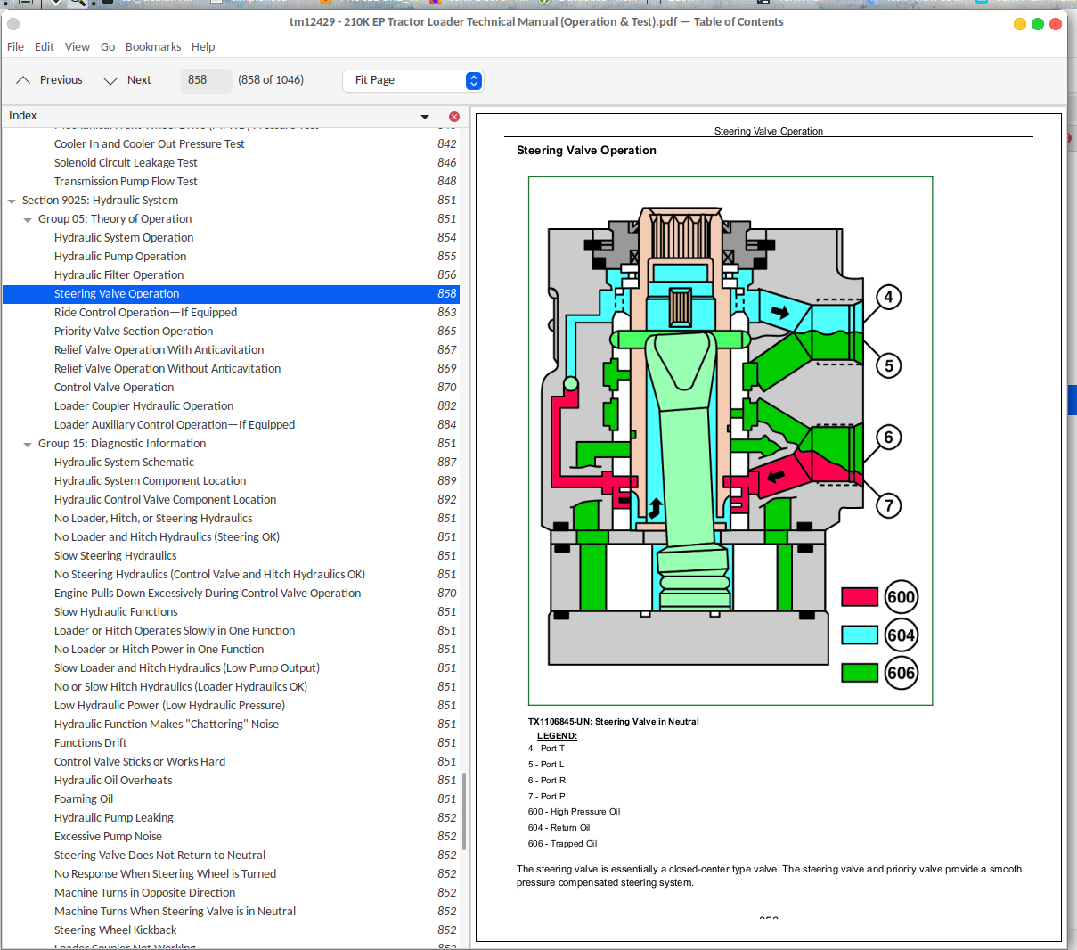
Steering Valve Operation............858
Ride Control Operation—If Equipped............863
Priority Valve Section Operation............865
Relief Valve Operation With Anticavitation............867
Relief Valve Operation Without Anticavitation............869
Control Valve Operation............870
Loader Coupler Hydraulic Operation............882
Loader Auxiliary Control Operation—If Equipped............884
Group 15: Diagnostic Information............851
Hydraulic System Schematic............887
Hydraulic System Component Location............889
Hydraulic Control Valve Component Location............892
No Loader, Hitch, or Steering Hydraulics............851
No Loader and Hitch Hydraulics (Steering OK)............851
Slow Steering Hydraulics............851
No Steering Hydraulics (Control Valve and Hitch Hydraulics OK)............851
Engine Pulls Down Excessively During Control Valve Operation............870
Slow Hydraulic Functions............851
Loader or Hitch Operates Slowly in One Function............851
No Loader or Hitch Power in One Function............851
Slow Loader and Hitch Hydraulics (Low Pump Output)............851
No or Slow Hitch Hydraulics (Loader Hydraulics OK)............851
Low Hydraulic Power (Low Hydraulic Pressure)............851
Hydraulic Function Makes "Chattering" Noise............851
Functions Drift............851
Control Valve Sticks or Works Hard............851
Hydraulic Oil Overheats............851
Foaming Oil............851
Hydraulic Pump Leaking............852
Excessive Pump Noise............852
Steering Valve Does Not Return to Neutral............852
No Response When Steering Wheel is Turned............852
Machine Turns in Opposite Direction............852
Machine Turns When Steering Valve is in Neutral............852
Steering Wheel Kickback............852
Loader Coupler Not Working............852
Group 20: Adjustments............852
Loader Bucket Self-Leveling Linkage and Return-To-Dig Switch Adjustment............944
Ride Control Accumulator Charge Procedure............949
Ride Control Accumulator Charge Check Procedure............952
Ride Control Accumulator Hydraulic Pressure Release Procedure............955
Group 25: Tests............852
JT02156A Digital Pressure And Temperature Analyzer Kit Installation............957
Hydraulic Oil Warm-Up Procedure............958
Fluid Sampling Procedure—If Equipped............959
Hydraulic Oil Sampling Procedure—If Equipped............964
Hydraulic Circuit Pressure Release............965
Hydraulic Pump Flow Test............967
Steering Load Sense Relief Valve Pressure Test............970
System Relief Valve Pressure Test............972
Hydraulic Oil Cooler Restriction Test............974
Circuit Relief Valve Test—With Remote Pump............977
Steering System Leakage Test............980
Steering Cylinder Leakage Test............983
Function Drift Test............985
Hydraulic Cylinder Leakage Test............987
Section 9031: Heating and Air Conditioning............989
Group 05: Theory of Operation............989
Air Conditioning System Cycle Of Operation............992
Group 15: Diagnostic Information............989
Air Conditioning and Heater System Component Location............996
Air Conditioning System Does Not Operate............989
Air Conditioner Does Not Cool Interior of Cab............989
Air Conditioner Runs Constantly, Too Cold............989
Interior Windows Continue to Fog............989
Heater System Does Not Operate............989
Heater Does Not Warm Interior of Cab............989
Group 25: Tests............989
Refrigerant Cautions and Proper Handling............1016
R134a Refrigerant Cautions............1017
R134a Oil Charge Capacity............1018
R134a Refrigerant Charge Capacity............1019
Air Conditioner and Heater Operational Checks............1020
Air Conditioner Compressor Clutch Test............1023
Air Conditioner High/Low Pressure Switch Test............1024
Air Conditioner Freeze Control Switch Test............1027
R134a Air Conditioning System Test............1030
Operating Pressure Diagnostic Chart............1033
Expansion Valve Test............1035
Blower Motor Speed Switch Test............1037
Blower Motor Resistor Test............1038
Blower Motor Test............1040
Air Conditioning On/Off Switch Test............1042
Air Conditioning System Leak Test............1043
Refrigerant Hoses and Tubing Inspection............1044
John Deere 210K EP Tractor Loader Diagnosis and Tests Service Technical Manual (TM12429)
![]()