
John Deere 470GLC Excavator Repair Service Manual (TM14155X19)
Complete Repair Service Technical Manual for John Deere 470GLC Excavator, with all the shop information to maintain, repair, and rebuild like professional mechanics.
John Deere 470GLC Excavator workshop technical manual (repair) includes:
* Numbered table of contents easy to use so that you can find the information you need fast.
* Detailed sub-steps expand on repair procedure information
* Numbered instructions guide you through every repair procedure step by step.
* Notes, cautions and warnings throughout each chapter pinpoint critical information.
* Bold figure number help you quickly match illustrations with instructions.
* Detailed illustrations, drawings and photos guide you through every procedure.
* Enlarged inset helps you identify and examine parts in detail.
tm14155x19 - John Deere 470GLC Excavator Technical Manual - Repair.pdf
tm14155x54 - John Deere Escavadeiras 470GLC.pdf
tm14155x63 - John Deere Excavadora 470GLC.pdf
PRODUCT DETAILS:
Total Pages: 761 pages
File Format: PDF/EPUB/MOBI/AZW (PC/Mac/Android/Kindle/iPhone/iPad; bookmarked, ToC, Searchable, Printable)
Language: Portuguese English Spanish
Models: John Deere - 470GLC Excavator - 1FF470GX_ _D473001—
TABLE OF CONTENTS.......1
Section 00: General Information.......15
Group 01: Safety.......15
Recognize Safety Information.......19
Follow Safety Instructions.......20
Operate Only If Qualified.......21
Wear Protective Equipment.......22
Avoid Unauthorized Machine Modifications.......23
Control Pattern.......24
Control Pattern Selector—If Equipped.......25
Add Cab Guarding for Special Uses.......26
Inspect Machine.......27
Stay Clear of Moving Parts.......28
Avoid High-Pressure Fluids.......29
Avoid High-Pressure Oils.......30
Work In Ventilated Area.......31
Avoid Static Electricity Risk When Refueling.......32
High Debris Applications.......34
Prevent Fires.......35
In Case of Machine Fire.......36
Prevent Battery Explosions.......37
Handle Chemical Products Safely.......38
Handle Starting Fluid Safely.......39
Decommissioning — Proper Recycling and Disposal of Fluids and Components.......40
Prepare for Emergencies.......41
Clean Debris from Machine.......42
Use Steps and Handholds Correctly.......43
Start Only From Operator's Seat.......44
Use and Maintain Seat Belt.......45
Prevent Unintended Machine Movement.......46
Avoid Work Site Hazards.......47
Keep Riders Off Machine.......49
Avoid Backover Accidents.......50
Avoid Machine Tip Over.......51
Inspect and Maintain ROPS.......53
Use Special Care When Lifting Objects.......54
Use Care When Swinging Machine.......55
Operate Boom With Care.......56
Avoid Power Lines.......57
Travel Safely.......58
Prevent Acid Burns.......59
Add and Operate Attachments Safely.......61
Park and Prepare for Service Safely.......62
Service Machines Safely.......63
Service Cooling System Safely.......64
Remove Paint Before Welding or Heating.......65
Make Welding Repairs Safely.......66
Drive Metal Pins Safely.......67
Use Proper Lifting Equipment.......68
Group 0003: Torque Values.......16
Metric Bolt and Cap Screw Torque Values.......71
Additional Metric Cap Screw Torque Values.......73
Unified Inch Bolt and Cap Screw Torque Values.......75
Service Recommendations for 37° Flare and 30° Cone Seat Connectors.......78
Service Recommendations for O-Ring Boss Fittings.......80
Service Recommendations for Flared Connections—Straight or Tapered Threads.......82
Service Recommendations for Flat Face O-Ring Seal Fittings.......84
O-Ring Boss Fittings In Aluminum Housing Service Recommendations—Excavators.......86
O-Ring Face Seal Fittings With SAE Inch Hex Nut and Stud End for High-Pressure Service Recommendations.......89
O-Ring Face Seal Fittings With Metric Hex Nut and Stud End for Standard Pressure Service Recommendations.......91
O-Ring Face Seal Fittings With Metric Hex Nut and Stud End for High-Pressure Service Recommendations.......94
Service Recommendations for Metric Series Four Bolt Flange Fitting.......97
Service Recommendations For Inch Series Four Bolt Flange Fittings.......99
Inch Series Four Bolt Flange Fitting for High-Pressure Service Recommendations.......101
Service Recommendations For Non-Restricted Banjo (Adjustable) Fittings.......103
Service Recommendations For O-Ring Boss Fittings With Shoulder.......106
Metric 24° O-Ring Seal DIN 20078 Service Recommendations.......109
Section 01: Tracks.......113
Group 0130: Track System.......113
Track Roller Remove and Install.......118
Track Roller Disassemble and Assemble.......122
Track Roller Pressure Test.......126
Track Carrier Roller Remove and Install.......129
Track Carrier Roller Disassemble and Assemble.......133
Metal Face Seals Repair.......136
Track Shoe Remove and Install.......139
Track Chain Remove and Install.......142
Track Chain Disassemble and Assemble.......149
Track Chain Repair to Replace Broken Part.......152
Sprocket Remove and Install.......158
Front Idler Remove and Install.......161
Front Idler Disassemble and Assemble.......163
Front Idler Pressure Test.......169
Track Adjuster and Recoil Spring Remove and Install.......172
Track Adjuster and Recoil Spring Disassemble and Assemble.......174
Track Adjuster Cylinder Disassemble and Assemble.......178
Section 02: Axles and Suspension Systems.......180
Group 0250: Axle Shaft, Bearings, and Reduction Gears.......180
Travel Gear Case Remove and Install.......185
Travel Gear Case Disassemble and Assemble.......189
Group 0260: Hydraulic System.......180
Travel Motor and Park Brake Remove and Install.......204
Travel Motor and Park Brake Disassemble and Assemble.......205
Park Brake Valve Disassemble and Assemble.......210
Counterbalance Valve Remove and Install.......214
Crossover Relief Valves Remove and Install.......215
Make-Up Check Valve Remove and Install.......216
Travel Speed Selector Valve Remove and Install.......217
Travel Motor and Park Brake Start-Up Procedure.......218
Section 04: Engine.......220
Group 0400: Removal and Installation.......220
Engine Remove and Install.......232
Section 05: Engine Auxiliary System.......243
Group 0510: Cooling Systems.......243
Radiator Remove and Install.......250
Hydraulic Oil Cooler Remove and Install.......638
Charge Air Cooler Remove and Install.......257
Fuel Cooler Remove and Install.......261
Cooling Package Remove and Install.......263
Fan, Fan Guard, and Fan Shroud Remove and Install.......271
Group 0560: External Fuel Supply Systems.......243
Fuel Tank Remove and Install.......279
Section 07: Damper Drive (Flex Coupling).......284
Group 0752: Elements.......284
Damper Drive (Flex Coupling) Remove and Install.......288
Section 17: Frame or Supporting Structure.......291
Group 1740: Frame Installation.......291
Welding on Machine.......294
Group 1749: Chassis Weights.......291
Counterweight Remove and Install.......299
Section 18: Operator's Station.......302
Group 1800: Removal and Installation.......302
Cab Remove and Install.......312
Group 1810: Operator Enclosure.......302
Windshield Remove and Install.......323
Windshield Disassemble and Assemble.......325
Sliding Windows Remove and Install.......335
Windowpanes Remove and Install.......337
Windowpane Dimensions.......338
Group 1821: Seat and Seat Belt.......302
Seat Remove and Install.......348
Seat Belt Remove and Install.......350
Mechanical Suspension Seat Disassemble and Assemble.......351
Group 1830: Heating and Air Conditioning.......302
R134a Refrigerant Cautions and Proper Handling.......354
R134a Refrigerant Oil Information.......355
R134a Refrigerant Recovery, Recycling, and Charging Station Installation Procedure.......357
Recover R134a Refrigerant.......359
Flush and Purge Air Conditioning System.......360
Evacuate R134a System.......363
Charge R134a System.......365
Air Conditioner Compressor Remove and Install.......367
Condenser Remove and Install.......369
Heater and Air Conditioner Remove and Install.......372
Receiver-Dryer Remove and Install.......376
Section 19: Sheet Metal and Styling.......378
Group 1910: Hood and Engine Side Shields.......378
Hood Remove and Install.......382
Engine Side Shields Remove and Install.......385
Group 1921: Grille and Grille Housing.......378
Cooling Package Door Remove and Install.......394
Section 33: Excavator.......396
Group 3302: Buckets.......396
Bucket Remove and Install.......400
Bucket Pin-Up Data.......401
Group 3340: Frames.......396
Bucket Links Remove and Install.......407
Arm Remove and Install.......411
Boom Remove and Install.......420
Inspect Pins, Bushings, and Bosses—Front Attachment.......426
Cylinder Specifications.......431
Bushings and Seal Remove and Install.......432
Group 3360: Hydraulic System.......396
Apply Vacuum to Hydraulic Oil Tank.......436
Hydraulic Circuit Pressure Release Procedure.......438
Pump 1 and 2 Remove and Install.......440
Pump 1 and 2 Disassemble and Assemble.......446
Pump 1 and 2 Inspection.......456
Pump 1 and 2 Start-Up Procedure.......457
Pump 1 and 2 Regulator Remove and Install.......459
Pump 1 and 2 Regulator Disassemble and Assemble.......463
Pilot Pump Remove and Install.......467
Pilot Pump Disassemble and Assemble.......469
Pilot Filter and Pressure Regulating Valve Remove and Install.......471
Pilot Filter and Pressure Regulating Valve Disassemble and Assemble.......473
Pilot Shutoff Solenoid Valve Remove and Install.......475
Pilot Shutoff Solenoid Valve Disassemble and Assemble.......478
Fan Drive Pump Remove and Install.......481
Fan Drive Pump Disassemble and Assemble.......487
Fan Drive Pump Regulator Remove and Install.......491
Fan Drive Pump Regulator Disassemble and Assemble.......492
Fan Drive Motor Remove and Install.......493
Fan Drive Motor Disassemble and Assemble.......496
Fan Drive Reversing Control Valve Remove and Install.......549
Fan Drive Reversing Control Valve Disassemble and Assemble.......502
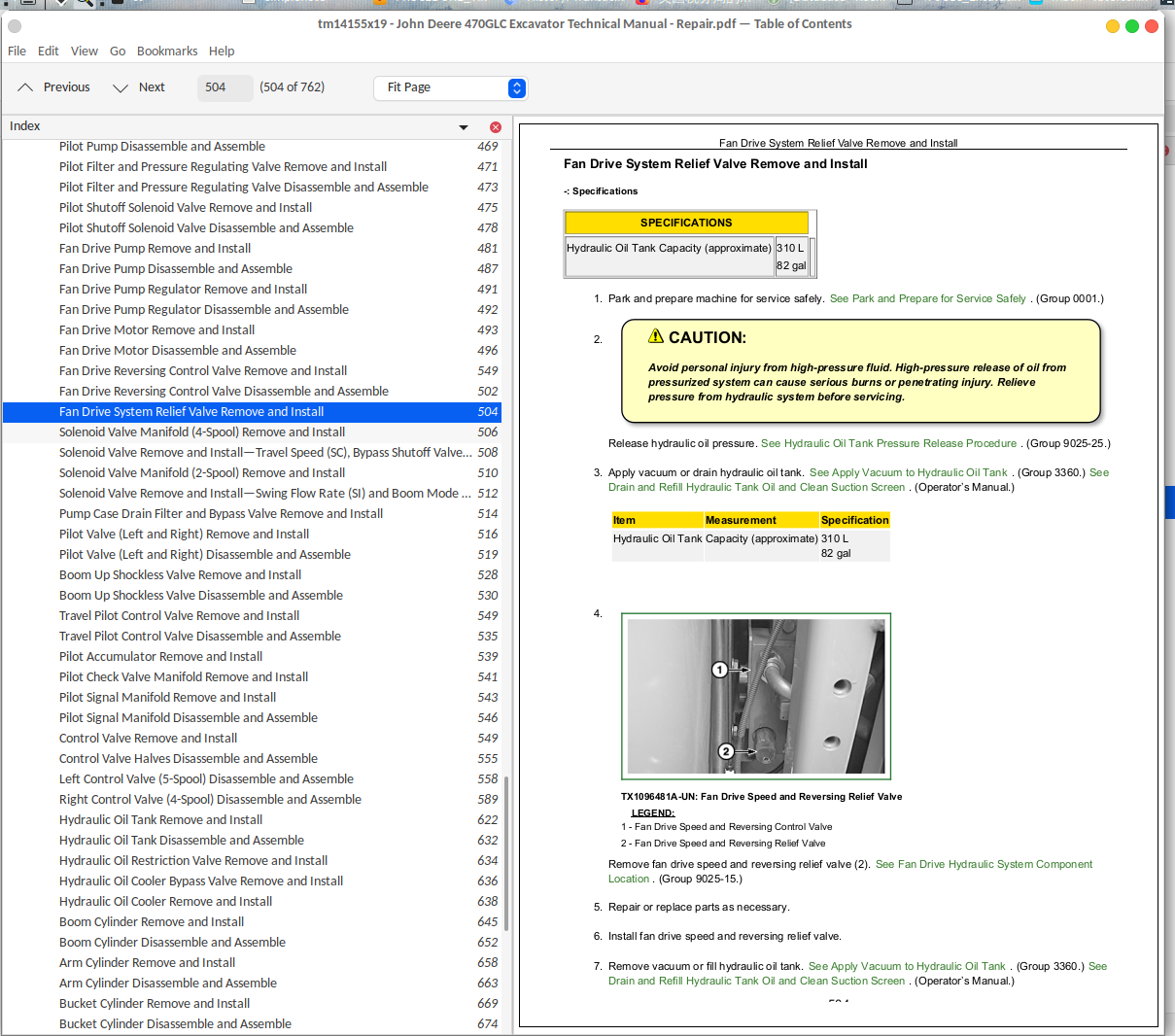
Fan Drive System Relief Valve Remove and Install.......504
Solenoid Valve Manifold (4-Spool) Remove and Install.......506
Solenoid Valve Remove and Install—Travel Speed (SC), Bypass Shutoff Valve (SF), Power Dig (SI), and Arm Flow Rate (SF).......508
Solenoid Valve Manifold (2-Spool) Remove and Install.......510
Solenoid Valve Remove and Install—Swing Flow Rate (SI) and Boom Mode (SC).......512
Pump Case Drain Filter and Bypass Valve Remove and Install.......514
Pilot Valve (Left and Right) Remove and Install.......516
Pilot Valve (Left and Right) Disassemble and Assemble.......519
Boom Up Shockless Valve Remove and Install.......528
Boom Up Shockless Valve Disassemble and Assemble.......530
Travel Pilot Control Valve Remove and Install.......549
Travel Pilot Control Valve Disassemble and Assemble.......535
Pilot Accumulator Remove and Install.......539
Pilot Check Valve Manifold Remove and Install.......541
Pilot Signal Manifold Remove and Install.......543
Pilot Signal Manifold Disassemble and Assemble.......546
Control Valve Remove and Install.......549
Control Valve Halves Disassemble and Assemble.......555
Left Control Valve (5-Spool) Disassemble and Assemble.......558
Right Control Valve (4-Spool) Disassemble and Assemble.......589
Hydraulic Oil Tank Remove and Install.......622
Hydraulic Oil Tank Disassemble and Assemble.......632
Hydraulic Oil Restriction Valve Remove and Install.......634
Hydraulic Oil Cooler Bypass Valve Remove and Install.......636
Hydraulic Oil Cooler Remove and Install.......638
Boom Cylinder Remove and Install.......645
Boom Cylinder Disassemble and Assemble.......652
Arm Cylinder Remove and Install.......658
Arm Cylinder Disassemble and Assemble.......663
Bucket Cylinder Remove and Install.......669
Bucket Cylinder Disassemble and Assemble.......674
Hydraulic Cylinder Bleed Procedure.......680
Section 43: Swing System.......681
Group 4350: Mechanical Drive Elements.......681
Swing Gear Case Remove and Install.......686
Swing Gear Case Disassemble and Assemble.......690
Swing Gear Case Start-Up Procedure.......702
Upperstructure Remove and Install.......703
Swing Bearing Remove and Install.......708
Swing Bearing Disassemble and Assemble.......712
Swing Bearing Upper Seal Install.......717
Swing Bearing Lower Seal Install.......718
Group 4360: Hydraulic System.......681
Center Joint Remove and Install.......724
Center Joint Disassemble and Assemble.......728
Center Joint Air Test.......732
Swing Motor and Park Brake Remove and Install.......733
Swing Motor and Park Brake Disassemble and Assemble.......736
Swing Motor and Park Brake Start-Up Procedure.......744
Crossover Relief Valve and Make-Up Check Valve Remove and Install.......746
Make-Up Check Valve Disassemble and Assemble.......749
Section 99: Dealer Fabricated Tools.......751
Group 9900: Dealer Fabricated Tools.......751
DF1063 Lift Bracket.......754
DFT1130 Adapter.......756
Center Joint (Rotary Manifold) Lifting Tool.......757
DFT1119 Pump Support.......758
DFT1220 Swing Gear Case Nut Spanner Wrench.......760
John Deere 470GLC Excavator Repair Service Manual (TM14155X19)
![]()