
John Deere 470GLC Excavator Diagnosis and Tests Service Technical Manual
Complete Diagnosis & Tests Technical Manual with electrical wiring diagrams for John Deere 470GLC Excavator, with workshop information to maintain, diagnose, and rebuild like professional mechanics.
John Deere 470GLC Excavator workshop Diagnosis & Tests technical manual includes:
* Numbered table of contents easy to use so that you can find the information you need fast.
* Detailed sub-steps expand on repair procedure information
* Numbered instructions guide you through every repair procedure step by step.
* Troubleshooting and electrical service procedures are combined with detailed wiring diagrams for ease of use.
* Notes, cautions and warnings throughout each chapter pinpoint critical information.
* Bold figure number help you quickly match illustrations with instructions.
* Detailed illustrations, drawings and photos guide you through every procedure.
* Enlarged inset helps you identify and examine parts in detail.
tm14154x19 - John Deere 470GLC Excavator Technical Manual (Operation and Test).pdf
tm14154x63 - John Deere Excavadora 470GLC.pdf
tm14154x54 - John Deere Escavadeira 470GLC.pdf
PRODUCT DETAILS:
Total Pages: 1,411 pages
File Format: PDF/EPUB/MOBI/AZW (PC/Mac/Android/Kindle/iPhone/iPad; bookmarked, ToC, Searchable, Printable)
Language: Portuguese Spanish English
Models: John Deere - 470GLC Excavator - 1FF470GX_ _D473001—
TABLE OF CONTENTS
Section 9000: General Information...25
Group 01: Safety.....25
Recognize Safety Information.....28
Follow Safety Instructions.....29
Operate Only If Qualified.....30
Wear Protective Equipment.....31
Avoid Unauthorized Machine Modifications.....32
Control Pattern.....33
Control Pattern Selector—If Equipped.....34
Add Cab Guarding for Special Uses.....35
Inspect Machine.....36
Stay Clear of Moving Parts.....37
Avoid High-Pressure Fluids.....38
Avoid High-Pressure Oils.....39
Work In Ventilated Area.....40
Avoid Static Electricity Risk When Refueling.....41
High Debris Applications.....43
Prevent Fires.....44
In Case of Machine Fire.....45
Prevent Battery Explosions.....46
Handle Chemical Products Safely.....47
Handle Starting Fluid Safely.....48
Decommissioning — Proper Recycling and Disposal of Fluids and Components.....49
Prepare for Emergencies.....50
Clean Debris from Machine.....51
Use Steps and Handholds Correctly.....52
Start Only From Operator's Seat.....53
Use and Maintain Seat Belt.....54
Prevent Unintended Machine Movement.....55
Avoid Work Site Hazards.....56
Keep Riders Off Machine.....58
Avoid Backover Accidents.....59
Avoid Machine Tip Over.....60
Inspect and Maintain ROPS.....62
Use Special Care When Lifting Objects.....63
Use Care When Swinging Machine.....64
Operate Boom With Care.....65
Avoid Power Lines.....66
Travel Safely.....67
Prevent Acid Burns.....68
Add and Operate Attachments Safely.....70
Park and Prepare for Service Safely.....71
Service Machines Safely.....72
Service Cooling System Safely.....73
Remove Paint Before Welding or Heating.....74
Make Welding Repairs Safely.....75
Drive Metal Pins Safely.....76
Use Proper Lifting Equipment.....77
Section 9001: Diagnostics.....78
Group 10: Main Controller (MCZ) Diagnostic Trouble Codes.....87
Main Controller (MCZ) Diagnostic Trouble Codes.....87
Controller Area Network 0 (CAN 0) Circuit Diagnostics.....88
Controller Area Network 1 (CAN 1) Circuit Diagnostics.....89
Interface Controller Area Network (N-CAN) Diagnostics.....90
Engine Controller Area Network (Engine CAN) Diagnostics.....91
011000.02 - Abnormal EEPROM.....78
011001.02 - Abnormal RAM.....78
011002.02 - Abnormal A/D Converter.....78
011003.03 - Abnormal Sensor Voltage.....78
011004.02 - CAN Communication Error 1.....78
011005.02 - CAN Communication Error 2.....78
011006.02 - Engine Control Module (ECM) Communication Error.....78
011007.02 - (CAN 0) Data Converter Communication Error 1.....78
011008.02 - (CAN 1) Data Converter Communication Error 2.....78
011009.02 - (CAN 0) Monitor Controller Communication Error 1.....78
011010.02 - (CAN 1) Monitor Controller Communication Error 2.....78
011011.02 - Body Controller Communication Error.....78
011100.02 - Abnormal Engine Speed.....78
011101.03 - Engine Speed Dial Sensor Circuit High.....78
011101.04 - Engine Speed Dial Sensor Circuit Low.....78
011200.03 - Pump 1 Delivery Pressure Sensor Circuit High.....78
011200.04 - Pump 1 Delivery Pressure Sensor Circuit Low.....78
011202.03 - Pump 2 Delivery Pressure Sensor Circuit High.....78
011202.04 - Pump 2 Delivery Pressure Sensor Circuit Low.....78
011301.03 - Swing Pressure Sensor Circuit High.....78
011301.04 - Swing Pressure Sensor Circuit Low.....78
011302.03 - Boom Up Pressure Sensor Circuit High.....78
011302.04 - Boom Up Pressure Sensor Circuit Low.....78
011303.03 - Arm In Pressure Sensor Circuit High.....78
011303.04 - Arm In Pressure Sensor Circuit Low.....78
011304.03 - Travel Pressure Sensor Circuit High.....78
011304.04 - Travel Pressure Sensor Circuit Low.....79
011325.03 - Bucket Curl Pressure Sensor Circuit High.....79
011325.04 - Bucket Curl Pressure Sensor Circuit Low.....79
011405.02 - Travel Speed Solenoid Feedback Current Abnormal.....79
011405.03 - Travel Speed Solenoid Feedback Current High.....79
011405.04 - Travel Speed Solenoid Feedback Current Low.....79
011408.02 - Bypass Shutoff Valve Solenoid Feedback Current Abnormal.....79
011408.03 - Bypass Shutoff Valve Solenoid Feedback Current High.....79
011408.04 - Bypass Shutoff Valve Solenoid Feedback Current Low.....79
011412.02 - Fan Pump Control Solenoid Feedback Current Abnormal.....79
011412.03 - Fan Pump Control Solenoid Feedback Current High.....79
011412.04 - Fan Pump Control Solenoid Feedback Current Low.....79
011428.02 - Arm Flow Rate Control Solenoid Feedback Current Abnormal.....79
011428.03 - Arm Flow Rate Control Solenoid Feedback Current High.....79
011428.04 - Arm Flow Rate Control Solenoid Feedback Current Low.....79
011459.02 - Idle Stop Relay Circuit Malfunction.....79
011802.03 - Boom Bottom Pressure Sensor Circuit Voltage High.....79
011802.04 - Boom Bottom Pressure Sensor Circuit Voltage Low.....79
011901.03 - Hydraulic Oil Temperature Sensor Circuit High Input.....79
011901.04 - Hydraulic Oil Temperature Sensor Circuit Low Input.....79
011940.02 - 4 Combination Bypass Cut Valve Control P/S Valve Abnormal FB.....79
011940.03 - 4 Combination Bypass Cut Valve Control P/S Valve FB High Current.....79
011940.04 - 4 Combination Bypass Cut Valve Control P/S Valve FB Low Current.....79
011941.02 - 3-Direction Valve Change Over Abnormal FB.....79
011941.03 - 3-Direction Valve Change Over FB High Current.....79
011941.04 - 3-Direction Valve Change Over FB Low Current.....79
011942.03 - Attachment Pressure Sensor Circuit Voltage High.....79
011942.04 - Attachment Pressure Sensor Circuit Voltage Low.....79
011944.03 - Pilot Pressure Sensor (5-Spool) Circuit Voltage High.....79
011944.04 - Pilot Pressure Sensor (5-Spool) Circuit Voltage Low.....79
011945.03 - Pilot Pressure Sensor (4-Spool) Circuit Voltage High.....79
011945.04 - Pilot Pressure Sensor (4-Spool) Circuit Voltage Low.....79
011946.02 - Engine Torque Receive Error.....79
011947.02 - Air Compressor Activation Receive Error.....80
011948.02 - Power Dig Solenoid Feedback Current Abnormal.....80
011948.03 - Power Dig Solenoid Feedback Current High.....80
011948.04 - Power Dig Solenoid Feedback Current Low.....80
011950.02 - Pump Control Valve Solenoid 2 Feedback Current Abnormal.....80
011950.03 - Pump Control Valve Solenoid 2 Feedback Current High.....80
011950.04 - Pump Control Valve Solenoid 2 Feedback Current Low.....80
011951.02 - Pump Control Valve Solenoid 1 Feedback Current Abnormal.....80
011951.03 - Pump Control Valve Solenoid 1 Feedback Current High.....80
011951.04 - Pump Control Valve Solenoid 1 Feedback Current Low.....80
011953.02 - Swing Flow Rate Solenoid Feedback Current Abnormal.....80
011953.03 - Swing Flow Rate Solenoid Feedback Current High.....80
011953.04 - Swing Flow Rate Solenoid Feedback Current Low.....80
011955.03 - Pump 2 Swash Angle Sensor Circuit High Input.....80
011955.04 - Pump 2 Swash Angle Sensor Circuit Low Input.....80
011956.03 - Pump 1 Swash Angle Sensor Circuit High Input.....80
011956.04 - Pump 1 Swash Angle Sensor Circuit Low Input.....80
011957.03 - Auxiliary 5 Pilot Pressure Sensor Circuit High Input.....80
011957.04 - Auxiliary 5 Pilot Pressure Sensor Circuit Low Input.....80
011958.03 - Auxiliary 4 Pilot Pressure Sensor Circuit High Input.....80
011958.04 - Auxiliary 4 Pilot Pressure Sensor Circuit Low Input.....80
011971.02 - Pump Control Valve Solenoid 1 Abnormal Learning.....80
011972.02 - Pump Control Valve Solenoid 2 Abnormal Learning.....80
011974.02 - Engine Torque Un-Calibration.....80
011975.02 - Engine Torque Calibration Abort.....80
011978.03 - Auxiliary 2 Pilot Pressure Sensor Circuit High Input.....80
011978.04 - Auxiliary 2 Pilot Pressure Sensor Circuit Low Input.....80
011979.03 - Auxiliary 1 Pilot Pressure Sensor Circuit High Input.....80
011979.04 - Auxiliary 1 Pilot Pressure Sensor Circuit Low Input.....80
011980.02 - Attachment Overload Switch P/S Valve Abnormal FB.....80
011980.03 - Attachment Overload Switch P/S Valve FB High Current.....80
011980.04 - Attachment Overload Switch P/S Valve FB Low Current.....80
011981.02 - Fan Reversing Solenoid 2 Feedback Current Abnormal.....80
011981.03 - Fan Reversing Solenoid 2 Feedback Current High.....81
011981.04 - Fan Reversing Solenoid 2 Feedback Current Low.....81
011982.02 - Fan Reversing Solenoid 1 Feedback Current Abnormal.....81
011982.03 - Fan Reversing Solenoid 1 Feedback Current High.....81
011982.04 - Fan Reversing Solenoid 1 Feedback Current Low.....81
011983.02 - Intake Air Temperature Receive Error.....81
011984.02 - Boost Temperature Receive Error.....81
011985.02 - Pump Control Valve Solenoid 2 Learning Failure.....81
011986.02 - Pump Control Valve Solenoid 1 Learning Failure.....81
011987.00 - Pump 2 Large Control Deviation.....81
011987.01 - Pump 2 Small Control Deviation.....81
011988.00 - Pump 1 Large Control Deviation.....81
011988.01 - Pump 1 Small Control Deviation.....81
011989.02 - Boom Overload Relief Solenoid Feedback Current Abnormal.....81
011989.03 - Boom Overload Relief Solenoid Feedback Current High.....81
011989.04 - Boom Overload Relief Solenoid Feedback Current Low.....81
011990.03 - Counterweight Lever Pressure Sensor Circuit Voltage High.....81
011990.04 - Counterweight Lever Pressure Sensor Circuit Voltage Low.....81
011992.03 - Pump 2 Control Pressure Sensor Circuit Voltage High.....81
011992.04 - Pump 2 Control Pressure Sensor Circuit Voltage Low.....81
011994.03 - Pump 1 Control Pressure Sensor Circuit Voltage High.....81
011994.04 - Pump 1 Control Pressure Sensor Circuit Voltage Low.....81
011995.03 - Arm Out Pressure Sensor Circuit High.....81
011995.04 - Arm Out Pressure Sensor Circuit Low.....81
011997.03 - Bucket Dump Pressure Sensor Circuit High.....81
011997.04 - Bucket Dump Pressure Sensor Circuit Low.....81
011998.03 - Boom Down Pressure Sensor Circuit High.....81
011998.04 - Boom Down Pressure Sensor Circuit Low.....81
020003.02 - Auto-Lubrication Alarm.....81
020005.02 - Engine Oil Level Alarm.....81
020006.02 - Coolant Level Alarm.....81
020008.02 - Hydraulic Oil Temperature Alarm.....81
020009.02 - Hydraulic Oil Cooling System Alarm.....81
020062.02 - Hydraulic Oil Temperature Alarm.....82
Group 20: Engine Control Module (ECM) Diagnostic Trouble Codes.....387
Engine Control Module (ECM) Diagnostic Trouble Codes.....387
000091.02 - Pedal Position Sensor 1 - 2 Voltage Correlation (P2138).....82
000091.03 - Pedal Position Sensor 1 Circuit High Input (P2123).....82
000091.03 - Pedal Position Sensor 2 Circuit High Input (P2128).....82
000091.04 - Pedal Position Sensor 1 Circuit Low Input (P2122).....82
000091.04 - Pedal Position Sensor 2 Circuit Low Input (P2127).....82
000100.03 - Engine Oil Pressure Sensor Circuit High Input (P0523).....82
000100.04 - Engine Oil Pressure Sensor Circuit Low Input (P0522).....82
000102.00 - Turbocharger Overboost Condition (P0234).....82
000102.03 - Turbocharger Boost Sensor Circuit High (P0238).....82
000102.04 - Turbocharger Boost Sensor Circuit Low (P0237).....82
000105.03 - Compressor Outlet Temperature Sensor Circuit High (P1113).....82
000105.04 - Compressor Outlet Temperature Sensor Circuit Low (P1112).....82
000108.03 - Barometric Pressure Sensor Circuit High (P2229).....82
000108.04 - Barometric Pressure Sensor Circuit Low (P2228).....82
000110.00 - Engine Coolant Over Temperature Condition (P0217).....82
000110.03 - Engine Coolant Temperature Sensor Circuit High (P0118).....82
000110.04 - Engine Coolant Temperature Sensor Circuit Low (P0117).....82
000157.03 - Fuel Rail Pressure Sensor Circuit High (P0193).....82
000157.04 - Fuel Rail Pressure Sensor Circuit Low (P0192).....82
000157.15 - Fuel Pressure Regulator Performance (P0089).....82
000158.03 - System Voltage High (P0563).....82
000172.03 - Intake Air Temperature Sensor Circuit High (P0113).....82
000172.04 - Intake Air Temperature Sensor Circuit Low (P0112).....82
000174.03 - Fuel Temperature Sensor System High Input (P0183).....82
000174.04 - Fuel Temperature Sensor System Low Input (P0182).....82
000190.00 - Engine Overspeed Condition (P0219).....82
0000628.02 - Internal Control Module Memory Check Sum Error (P0601).....82
000633.07 - Fuel Rail/System Pressure - Too Low (P0087).....82
000636.02 - Camshaft Position Sensor Circuit (P0340).....82
000636.07 - Crankshaft Position - Camshaft Position Correlation Error (P0016).....82
000639.02 - Lost Communication With CAN (U0101).....83
000639.19 - Control Module Communication Bus Off (U0073).....83
000651.05 - Injector Circuit Open - Cylinder 1 (P0201).....83
000652.05 - Injector Circuit Open - Cylinder 2 (P0202).....83
000653.05 - Injector Circuit Open - Cylinder 3 (P0203).....83
000654.05 - Injector Circuit Open - Cylinder 4 (P0204).....83
000655.05 - Injector Circuit Open - Cylinder 5 (P0205).....83
000656.05 - Injector Circuit Open - Cylinder 6 (P0206).....83
000676.05 - Glow Relay Circuit Error (P0380).....83
000677.05 - Starter Relay Circuit Error (P0615).....83
000723.02 - Crankshaft Position Sensor Circuit (P0335).....83
000723.08 - Crankshaft Position Sensor Circuit Range/Performance (P0336).....83
001077.02 - Internal Control Module CPU Error (P0606).....83
001079.02 - Sensor Reference Voltage 1 Circuit (P0641).....83
001080.02 - Sensor Reference Voltage 2 Circuit (P0651).....83
001239.01 - Fuel Rail Pressure Too Low (P1093).....83
001239.31 - Fuel Rail Pressure Too Low (P1093).....83
001347.03 - Fuel Pressure Regulator Control Circuit High (P0092).....83
001347.04 - Fuel Pressure Regulator Control Circuit Low (P0091).....83
001347.12 - Fuel Pressure Regulator 1 Solenoid Control Circuit (P1062).....83
001348.03 - Fuel Pressure Regulator 2 Control Circuit High (P2296).....83
001348.04 - Fuel Pressure Regulator 2 Control Circuit Low (P2295).....83
001348.12 - Fuel Pressure Regulator 2 Solenoid Control Circuit (P1063).....83
001381.03 - Fuel Pressure Sensor Circuit High (P1294).....83
001381.04 - Fuel Pressure Sensor Circuit Low (P1293).....83
001485.05 - ECM Power Relay Control Circuit Open (P0685).....83
001485.06 - ECM Power Relay Control Circuit High (P0687).....83
010001.02 - EGR Sensor Circuit (P0409).....83
010001.13 - EGR Position Fault (P1404).....83
010002.02 - EGR Control Circuit Range/Performance (P0404).....83
010003.02 - Fuel Injector Group 1 Supply Voltage Circuit (P2146).....83
010004.02 - Fuel Injector Group 2 Supply Voltage Circuit (P2149).....83
010005.02 - Injector Positive Voltage Control Circuit Group 1 (P1261).....83
010006.02 - Injector Positive Voltage Control Circuit Group 2 (P1262).....84
010007.02 - Internal Control Module CPU IC Error (P0606).....84
010008.02 - Internal Control Module A/D Processing Performance (P060B).....84
010009.02 - Sensor Reference Voltage 3 Circuit (P0697).....84
010010.02 - Sensor Reference Voltage 4 Circuit (P1655).....84
010013.02 - Control Module Long Term Memory Performance (P1621).....84
010032.02 - Internal Control Module QR Code Error (P0602).....84
010033.02 - Internal Control Module RAM Error (P0604).....84
Group 30: Monitor Controller (DSZ) Diagnostic Trouble Codes.....464
Monitor Controller (DSZ) Diagnostic Trouble Codes.....464
013000.02 - Flash Memory Failure 1.....84
013001.02 - Flash Memory Failure 2.....84
013002.02 - ECU Communication Error.....84
013003.02 - Main Controller (MCZ) Communication Error 1.....84
013004.02 - Main Controller (MCZ) Communication Error 2.....84
013005.02 - Monitor Controller (DSZ) Communication Error 1.....84
013006.02 - Monitor Controller (DSZ) Communication Error 2.....84
013007.02 - Machine Controller (BCZ) Communication Error.....84
020113.02 - System Error Alarm.....84
Group 40: Information Controller (ICF) Diagnostic Trouble Codes.....84
Information Controller (ICZ) Diagnostic Trouble Codes.....475
013303.02 - Abnormal Monitor Internal Temperature Sensor.....84
013304.02 - Alternator Alarm.....84
013305.02 - Abnormal Manual Glow EXT Output.....84
013310.03 - Coolant Temperature Sensor Short Circuit.....84
013311.03 - Fuel Level Sensor Open Circuit.....84
013311.04 - Fuel Level Sensor Shorted Circuit.....84
014000.02 - CAN Communication Error 1.....84
014001.02 - Flash Memory Read/Write Error.....84
014002.02 - External RAM Read/Write Error.....84
014003.02 - Abnormal EEPROM.....84
014006.02 - Communication Terminal: Communication Error.....84
014008.02 - Abnormal Internal RAM.....84
014021.02 - Communication Terminal Security Error.....85
014022.02 - SIM Card Error.....85
014023.02 - Security Error.....85
020100.02 - Overheat Alarm.....85
020101.02 - Engine Warning Alarm.....85
020102.02 - Engine Oil Pressure Alarm.....85
020103.02 - Alternator Alarm.....85
020104.02 - Fuel Level Alarm.....85
020105.02 - Hydraulic Oil Filter Restriction Alarm.....85
020106.02 - Air Cleaner Restriction Alarm.....85
020107.02 - Water Separator Alarm.....85
020109.02 - Pilot Control Shutoff Lever Alarm.....85
020110.02 - Fuel Filter Restriction Alarm.....85
020114.02 - Overheat Alarm.....85
020146.02 - Fuel Temperature Increase Alarm.....85
020149.02 - EGR Gas Temperature Alarm.....85
Group 50: Air Conditioner Controller (ACF) Diagnostic Trouble Codes.....522
Air Conditioner Controller (ACF) Diagnostic Trouble Codes.....522
11 - Open Circuit in Air Recirculation Sensor.....85
12 - Short-Circuited Air Recirculation Sensor.....85
13 - Open Circuit in Ambient Air Temperature Sensor.....85
14 - Short-Circuited Ambient Air Temperature Sensor.....85
18 - Short-Circuited Solar Radiation Sensor.....85
21 - Open Circuit in Air Conditioner Freeze Control Switch.....85
22 - Short-Circuited Air Conditioner Freeze Control Switch.....85
43 - Abnormal Air Conditioner and Heater Blower Port Change Servomotor.....85
44 - Abnormal Air Conditioner and Heater Mixer Servomotor.....85
51 - Abnormal High/Low Refrigerant Pressure.....85
91 - Communication Error.....85
92 - CAN Bus Off Error.....85
Section 9005: Operational Checkout Procedure.....555
Group 10: Operational Checkout Procedure.....555
Operational Checkout.....622
Section 9010: Engine.....688
Group 05: Theory of Operation.....914
Isuzu Engine.....705
Engine Fuel System Component Location.....691
Engine Cooling System Component Location.....693
Cold Weather Starting Aid.....695
Engine Speed Control System Operation.....914
Group 15: Diagnostic Information.....688
Isuzu Engine.....705
Group 20: Adjustments.....688
Isuzu Engine.....705
Group 25: Tests.....688
Isuzu Engine.....705
Section 9015: Electrical System.....706
Group 05: System Information.....706
Electrical Diagram Information.....718
Group 10: System Diagrams.....706
Explanation of Wire Markings.....727
Fuse and Relay Specifications.....728
System Functional Schematic, Component Location, and Wiring Diagram Master Legend.....733
System Functional Schematic.....742
Cab Harness (W1) Component Location.....755
Cab Harness (W1) Wiring Diagram.....759
Machine Harness (W2) Component Location.....764
Machine Harness (W2) Wiring Diagram.....766
Monitor Harness (W3) Component Location.....769
Monitor Harness (W3) Wiring Diagram.....770
Engine Harness (W4) Component Location.....772
Engine Harness (W4) Wiring Diagram.....774
Engine Sub Harness (W6) Component Location.....775
Engine Sub Harness (W6) Wiring Diagram.....777
Pump Harness (W8) Component Location.....778
Pump Harness (W8) Wiring Diagram.....779
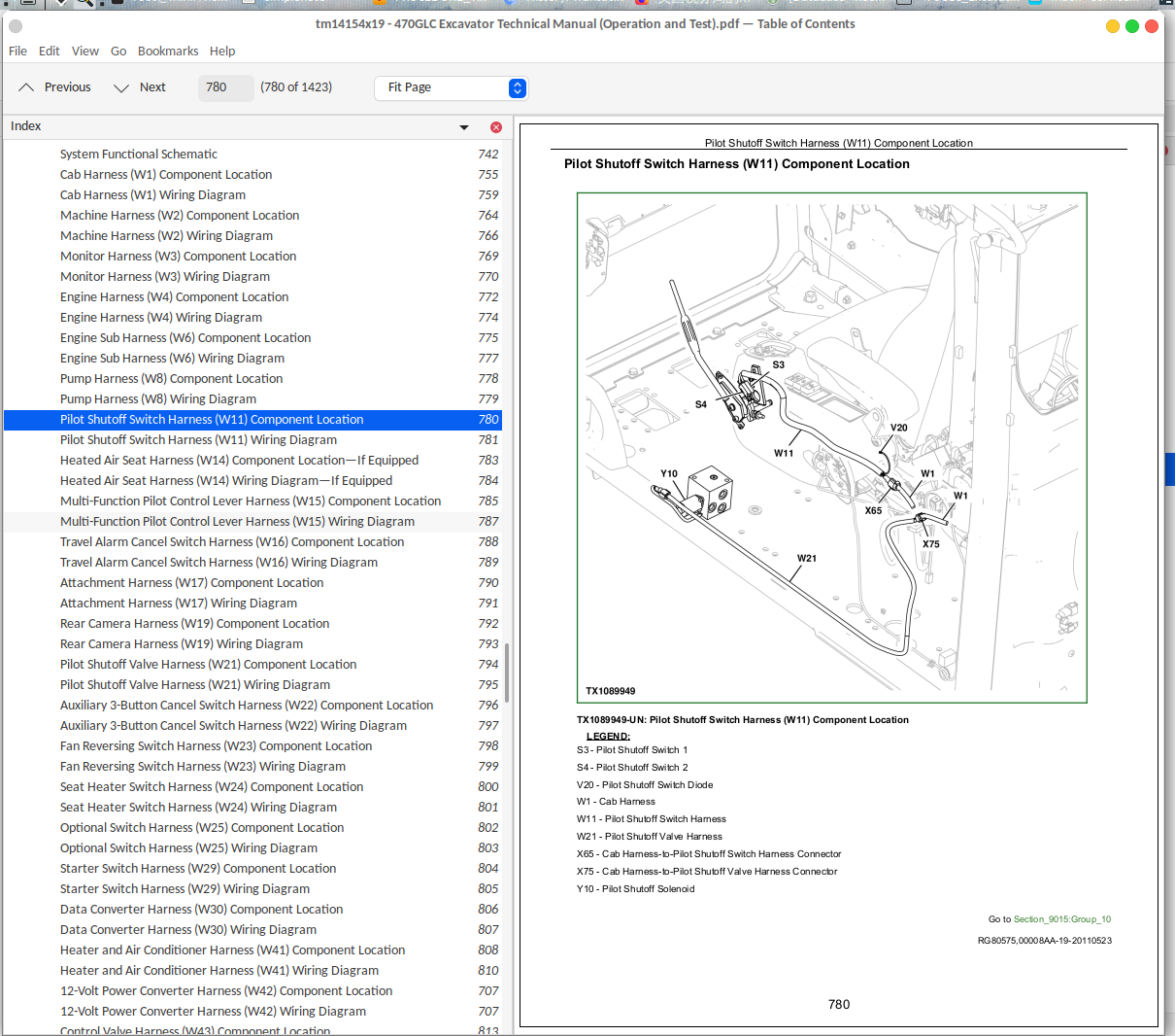
Pilot Shutoff Switch Harness (W11) Component Location.....780
Pilot Shutoff Switch Harness (W11) Wiring Diagram.....781
Heated Air Seat Harness (W14) Component Location—If Equipped.....783
Heated Air Seat Harness (W14) Wiring Diagram—If Equipped.....784
Multi-Function Pilot Control Lever Harness (W15) Component Location.....785
Multi-Function Pilot Control Lever Harness (W15) Wiring Diagram.....787
Travel Alarm Cancel Switch Harness (W16) Component Location.....788
Travel Alarm Cancel Switch Harness (W16) Wiring Diagram.....789
Attachment Harness (W17) Component Location.....790
Attachment Harness (W17) Wiring Diagram.....791
Rear Camera Harness (W19) Component Location.....792
Rear Camera Harness (W19) Wiring Diagram.....793
Pilot Shutoff Valve Harness (W21) Component Location.....794
Pilot Shutoff Valve Harness (W21) Wiring Diagram.....795
Auxiliary 3-Button Cancel Switch Harness (W22) Component Location.....796
Auxiliary 3-Button Cancel Switch Harness (W22) Wiring Diagram.....797
Fan Reversing Switch Harness (W23) Component Location.....798
Fan Reversing Switch Harness (W23) Wiring Diagram.....799
Seat Heater Switch Harness (W24) Component Location.....800
Seat Heater Switch Harness (W24) Wiring Diagram.....801
Optional Switch Harness (W25) Component Location.....802
Optional Switch Harness (W25) Wiring Diagram.....803
Starter Switch Harness (W29) Component Location.....804
Starter Switch Harness (W29) Wiring Diagram.....805
Data Converter Harness (W30) Component Location.....806
Data Converter Harness (W30) Wiring Diagram.....807
Heater and Air Conditioner Harness (W41) Component Location.....808
Heater and Air Conditioner Harness (W41) Wiring Diagram.....810
12-Volt Power Converter Harness (W42) Component Location.....707
12-Volt Power Converter Harness (W42) Wiring Diagram.....707
Control Valve Harness (W43) Component Location.....813
Control Valve Harness (W43) Wiring Diagram.....814
Boom Switch Harness (W47) Component Location.....815
Boom Switch Harness (W47) Wiring Diagram.....816
Cab Light Relay Harness (W48) Component Location.....817
Cab Light Relay Harness (W48) Wiring Diagram.....818
Cab Light Harness (W49) Component Location.....819
Cab Light Harness (W49) Wiring Diagram.....820
Auxiliary Solenoid Harness (W61) Component Location.....821
Auxiliary Solenoid Harness (W61) Wiring Diagram.....823
Engine Coolant Level Harness (W63) Component Location.....825
Engine Coolant Level Harness (W63) Wiring Diagram.....826
Water-in-Fuel (WIF) Sensor Harness (W64) Component Location.....827
Water-in-Fuel (WIF) Sensor Harness (W64) Wiring Diagram.....828
Attachment Pressure Sensor Harness (W66) Component Location.....829
Attachment Pressure Sensor Harness (W66) Wiring Diagram.....830
Cab Roof Light Harness (W67) Component Location.....831
Cab Roof Light Harness (W67) Wiring Diagram.....832
Fan Reversing Solenoid Jumper Harness (W70) Component Location.....833
Fan Reversing Solenoid Jumper Harness (W70) Wiring Diagram.....834
Satellite (SAT) Harness (W6003) Component Location—If Equipped.....835
Satellite (SAT) Harness (W6003) Wiring Diagram—If Equipped.....836
JDLink™ Harness (W6004) Component Location.....837
JDLink™ Harness (W6004) Wiring Diagram.....838
Group 15: Sub-System Diagnostics.....708
Controller Area Network (CAN) Theory of Operation.....914
Starting and Charging Circuit Theory of Operation.....914
Monitor Controller (DSZ) Circuit Theory of Operation.....914
Engine Control Module (ECM) Circuit Theory of Operation.....914
Travel Alarm Circuit Theory of Operation.....914
Machine Controller (BCZ) Circuit Theory of Operation.....914
Main Controller (MCZ) Circuit Theory of Operation.....914
Windshield Wiper and Washer Circuit Theory of Operation.....914
Lighting Circuit Theory of Operation.....914
Pilot Shutoff Circuit Theory of Operation.....914
Attachment Control Circuit Theory of Operation.....914
Group 16: Monitor Operation.....914
Service Menu.....902
Troubleshooting.....904
Monitoring.....905
Controller Version.....912
Issued Warning Record.....913
Operation.....914
Machine Setting.....915
Monitor Setting.....921
Alarm Setting.....924
Engine Setting.....925
Maintenance Mode.....926
Rear View Camera Troubleshooting.....927
Group 20: References.....709
Reading Diagnostic Trouble Codes with Monitor Display.....931
Service ADVISOR™ Diagnostic Application.....932
Service ADVISOR™ Connection Procedure.....933
Reading Diagnostic Trouble Codes with Service ADVISOR™ Diagnostic Application.....935
Clearing Engine Diagnostic Trouble Codes.....938
MPDr Application.....945
MPDr Connection Procedure.....946
Pump Learning Procedure.....948
Torque Calibration Procedure.....951
Pump Swash Angle Control Pressure Offset Adjustment Procedure.....954
Electrical Component Specifications.....959
Alternator Test.....962
Controller Area Network (CAN) Circuit Test.....964
Electrical Component Checks.....970
Battery Remove and Install.....979
Rear Cover Remove and Install.....981
Main Controller (MCZ) Remove and Install.....983
Engine Control Module (ECM) Remove and Install.....985
Monitor Controller (DSZ) Remove and Install.....987
Section 9020: Power Train.....989
Group 05: Theory of Operation.....914
Track Adjuster and Recoil Spring Operation.....992
Travel Gear Case Operation.....994
Group 15: Diagnostic Information.....989
Noisy or Loose Track Chain.....989
Tight Track Chain.....989
Frequent Track Chain Sag Adjustment Required.....989
Excessive Oil Leakage From Front Idler, Track Rollers, or Carrier Rollers.....989
Bent Track Shoes.....989
Section 9025: Hydraulic System.....1016
Group 05: Theory of Operation.....914
Hydraulic System Operation.....1021
Fan Drive Hydraulic System Operation.....1022
Pilot System Operation.....1025
Pressure Regulating Valve and Filter Operation.....1026
Pilot Shutoff Solenoid Valve Operation.....1028
Pilot Control Valve Operation.....1063
Travel Pilot Control Valve Operation.....1063
Boom Up Shockless Valve Operation.....1039
Pilot Operation of Control Valve Operation.....1063
Pilot Signal Manifold Operation.....1044
Pump 1, Pump 2, and Fan Drive Gear Case Operation.....1052
Pump 1 and Pump 2 Regulator Operation.....1055
Fan Pump Control Solenoid Valve Operation.....1058
Engine Speed Sensing Control Circuit Operation.....1061
Control Valve Operation.....1063
Control Valve Check Valves Identification and Operation.....1075
Main Relief Valve Circuit Operation.....1078
Circuit Relief and Anticavitation Valve Operation.....1083
Travel Flow Combiner Valve Circuit Operation.....1085
Boom Lower Meter-In Cut Valve Operation.....1088
Arm Regenerative Valve Circuit Operation.....1092
Bucket Regenerative Valve Circuit Operation.....1096
Boom and Arm Reduced Leakage Valves Operation.....1099
Arm 1 Flow Rate Control Valve Circuit Operation.....1102
Arm 2 Flow Rate Control Valve Circuit Operation.....1106
Boom Mode Circuit Operation.....1111
Boom Flow Rate Control Valve Circuit Operation.....1114
Swing Flow Rate Control Valve Circuit Operation.....1118
Auxiliary Flow Combiner Valve and Bypass Shutoff Valve Operation.....1122
Swing Gear Case Operation.....1129
Swing Motor, Crossover Relief Valve, and Make-Up Check Valve Operation.....1130
Swing Motor Park Brake Release Circuit Operation.....1134
Center Joint Operation.....1135
Travel Motor and Park Brake Circuit Operation.....1136
Travel Motor Speed Circuit Operation.....1138
Boom, Arm, and Bucket Cylinder Operation.....1140
Return Filter Operation.....1142
Auxiliary High Flow Line Kit Operation.....1143
Two-Way Solenoid Kit Operation.....1149
Two-Way Hydraulic Foot Pedal Control Kit Operation.....1152
Group 15: Diagnostic Information.....1017
All Hydraulic Functions Slow.....1017
Hydraulic Oil Overheats.....1017
No Hydraulic Functions.....1017
No Hydraulic Functions—Electrical Checks.....1017
Right Travel or Bucket Functions Slow During Single Operation.....914
Left Travel or Swing Functions Slow During Single Operation.....914
Function Does Not Stop When Control Lever Released.....1017
Load Drifts Down When Control Lever is in Neutral Position.....1017
Load Falls When Control Valve is Actuated To Raise Load.....1017
Power Dig Inoperable.....1017
H/P (High Power) Function Does Not Operate, PWR (Power) Mode is Normal.....1017
Boom Down Does Not Function, Moves Slowly, or is Erratic, all Other Functions Normal.....1017
Arm In Does Not Function, Moves Slowly, or is Erratic, all Other Functions Normal.....1017
Bucket Curl Slow During Digging Operation.....914
Boom Up or Arm Out Slow When Combined With Swing.....1017
Swing Speed Slow During Arm In Function.....1017
Boom Cannot Raise Track Off Ground.....1017
Swing Function Does Not Operate in Both Directions.....1017
Swing Speed Slow in Both Directions.....1017
Swing Speed Slow or Does Not Operate in One Direction.....1017
Machine Freewheels Down an Incline.....1017
Track Will Not Move in Either Direction.....1017
Travel is Slow or Weak While Turning.....1017
Machine Mistracks.....1018
Machine Mistracks Left During Combined Travel and Dig Functions.....1018
Machine Will Not Shift Into Fast (rabbit) Speed.....1018
Pump 1, Pump 2, Fan Drive Pump, and Pilot Pump Line Identification.....1221
Control Valve Line Identification.....1222
Swing Motor Line Identification.....1225
Pilot Control Line Connections.....1226
Travel Hydraulic System Component Location.....1247
Travel Hydraulic System Line Connections.....1249
Auxiliary Attachment Schematic.....1232
Hydraulic System Schematic.....1236
Hydraulic System Component Location.....1247
Hydraulic System Line Connections.....1249
Fan Drive Hydraulic System Schematic.....1251
Fan Drive Hydraulic System Component Location.....1253
Group 25: Tests.....1018
JT05800 Digital Thermometer Installation.....1255
JT02156A Digital Pressure and Temperature Analyzer Kit Installation.....1256
General Hydraulic Oil Cleanup Procedure.....1257
Hydraulic Component Failure Cleanup Procedure.....1260
Hydraulic Oil Tank Pressure Release Procedure.....1263
Hydraulic Oil Warm-Up Procedure.....1264
Pilot Pressure Regulating Valve Test and Adjustment.....1267
Control Valve Spool Actuating Pilot Pressure Test.....1271
Travel Speed Solenoid Valve (Port SC) Test and Adjustment.....1274
Bypass Shutoff Valve Solenoid Valve (Port SF) Test and Adjustment.....1279
Power Dig Solenoid Valve (Port SI) Test and Adjustment.....1284
Arm Flow Rate Control Solenoid Valve (Port SG) Test and Adjustment.....1289
Boom Overload Relief Solenoid Valve (Port SC) Test and Adjustment.....1294
Swing Flow Rate Solenoid Valve (Port SI) Test and Adjustment.....1299
Main Relief and Power Dig Valve Test and Adjustment.....1304
Circuit Relief Valve Test and Adjustment.....1310
Boom Mode Relief Valve Test and Adjustment.....1315
Pump Servo Piston Minimum Flow Test and Adjustment.....1320
Pump Servo Piston Maximum Flow Test and Adjustment.....1323
Swing Motor Crossover Relief Valve Test and Adjustment.....1326
Travel Motor Crossover Relief Valve Test and Adjustment.....1330
Swing Motor Leakage Test.....1336
Travel Motor Leakage Test.....1341
Cylinder Drift Test—Boom, Arm, and Bucket.....1344
Pump Flow Test.....1347
Pump Calibration.....1354
Fan Speed Test.....1355
Fan Motor Case Drain Test.....1358
Fan Drive Pump Flow Test.....1361
Fan Drive System Relief Valve Test and Adjustment.....1364
Section 9031: Heating and Air Conditioning.....1369
Group 05: Theory of Operation.....914
Air Conditioning System Cycle of Operation.....1372
Group 15: Diagnostic Information.....1369
Air Conditioning System Does Not Operate.....1369
Air Conditioning System Does Not Cool Interior of Cab.....1369
Air Conditioning System Runs Constantly, Too Cold.....1369
Heating System Does Not Operate.....1369
Heating System Does Not Warm Interior of Cab.....1369
Interior Windows Continue to Fog.....1369
Heater and Air Conditioner Component Location.....1397
Group 25: Tests.....1369
R134a Refrigerant Cautions and Proper Handling.....1399
R134a Oil Charge Capacity.....1400
R134a Refrigerant Charge Capacity.....1401
Heater and Air Conditioner Operational Checks.....1402
Air Conditioner Compressor Clutch Test.....1405
R134a Refrigerant Leak Test.....1406
R134a Refrigerant Hoses and Tubing Inspection.....1407
Air Conditioner High/Low-Pressure Switch Test.....1408
Air Conditioner Freeze Control Switch Test.....1411
Air Conditioning System Test.....1412
Operating Pressure Diagnostic Chart.....1416
Air Conditioner Compressor Belt Check and Adjustment.....1418
Section 9900: Dealer Fabricated Tools.....1419
Group 99: Dealer Fabricated Tools.....1419
DFT1218 Split Flange Hose Cap.....1421
John Deere 470GLC Excavator Diagnosis and Tests Service Technical Manual
![]()