
John Deere OEM Engine Accessories Component Technical Manual (CTM67)
Complete Component Technical Manual for John Deere OEM Engine Accessories, with all the technical information to maintain, diagnose, repair, rebuild like professional mechanics.
John Deere OEM Engine Accessories workshop service repair manual includes:
* Numbered table of contents easy to use so that you can find the information you need fast.
* Detailed sub-steps expand on repair procedure information
* Numbered instructions guide you through every repair procedure step by step.
* Troubleshooting and electrical service procedures are combined with detailed wiring diagrams for ease of use.
* Notes, cautions and warnings throughout each chapter pinpoint critical information.
* Bold figure number help you quickly match illustrations with instructions.
* Detailed illustrations, drawings and photos guide you through every procedure.
* Enlarged inset helps you identify and examine parts in detail.
PRODUCT DETAILS:
Total Pages: 611 pages
File Format: PDF (bookmarked, ToC, Searchable, Printable, high quality) & EPUB/MOBI/AZW for Kindle/iPad/iPhone/Android.
Language: English
ctm67 - John Deere OEM Engine Accessories Component Technical Manual.pdf
ctm67 - John Deere OEM Engine Accessories Component Technical Manual.epub
Foreword
This Component Technical Manual (CTM) contains the latest available instructions necessary to repair OEM engine accessories. It includes theory of operation, and diagnostic and testing procedures to help troubleshoot and understand potential failure modes.
The information is organized in groups for the various components requiring service instruction. At the beginning of each repair group are summary listings of all applicable essential tools, service equipment and tools, other materials needed to do the job, service parts kits, specifications, wear tolerances, and torque values.
Component Technical Manuals are concise service guides for specific components. Component technical manuals are written as stand-alone manuals covering multiple machine applications.
Fundamental service information is available from other sources covering basic theory of operation, fundamentals of troubleshooting, general maintenance, and basic types of failures and their causes.
MAIN SECTIONS
Foreword
Section : OEM Engine Accessories
Group 05: Safety
Prepare for Emergencies
Prevent Battery Explosions
Handling Batteries Safely
Handle Chemical Products Safely
Avoid High-Pressure Fluids
Support Machine Properly
Prevent Machine Runaway
Stay Clear of Rotating Drivelines
Handle Starting Fluid Safely
Wear Protective Clothing
Work in Clean Area
Service Machines Safely
Work In Ventilated Area
Illuminate Work Area Safely
Replace Safety Signs
Use Proper Lifting Equipment
Remove Paint Before Welding or Heating
Install Fan Guards
Avoid Hot Parts
Avoid Heating Near Pressurized Fluid Lines
Avoid Harmful Asbestos Dust
Practice Safe Maintenance
Use Proper Tools
Dispose of Waste Properly
Live With Safety
Group 10: General Information
About This Manual
Unified Inch Bolt and Screw Torque Values
Metric Bolt and Screw Torque Values
Group 20: Electrical System Information and Wiring Diagrams
Electrical Circuit Malfunctions
High Resistance Circuit
Open Circuit
Grounded Circuit
Shorted Circuit
Multimeter
Seven Step Electrical Test Procedure
Wiring Diagram and Schematic Information
Reading a System Functional Schematic
Reading a Wiring Diagram
Electrical Schematic Symbols
Component Identification Table
Engine Wiring Diagram Legend—North American Series 300, 400, 500 and 700 Engines and Early Model European (Saran) Series 300 Engines
Wiring Diagram—North American Series 300, 400 and 500 Engines
Wiring Diagram—North American Series 700 (8955) Engines
Wiring Diagram—European (Saran) Series 300 Engines (Early Model)
Engine Wiring Diagram Legend— is a registered trademark of Deere & Company 2.9 L, 4.5 L, 6.8 L and 8.1 L Engines (Without ECU)
Engine Wiring Diagram— is a registered trademark of Deere & Company 2.9 L, 4.5 L, 6.8 L and 8.1 L Engines (Without ECU)
Engine Wiring Diagram Legend— is a registered trademark of Deere & Company 10.5 L and 12.5 L Engines (With Lucas ECU) Wiring diagram shown does not show ECU (Engine Control Unit) components. See engine Operation and Diagnostics Manual CTM115 for ECU components and wiring diagrams.
Engine Wiring Diagram— is a registered trademark of Deere & Company 10.5 L and 12.5 L Engines (With Lucas ECU)
Engine Wiring Diagram— is a registered trademark of Deere & Company 8.1 L, 10.5 L and 12.5 L Engines (With John Deere ECU)
Engine Wiring Diagram— is a registered trademark of Deere & Company 8.1 L, 10.5 L and 12.5 L Engines (With John Deere ECU) (Continued)
Engine Wiring Diagram—PowerTech Plus 4.5 L, 6.8 L, 9.0 L and 13.5 L Engines
Engine Wiring Diagram—PowerTech Plus 4.5 L, 6.8 L, 9.0 L and 13.5 L Engines (Continued)
Engine Wiring Diagram—PowerTech Plus 4.5 L, 6.8 L, 9.0 L and 13.5 L Engines (Continued)
Engine Wiring Diagram—Saran AEZ Instrument Panel
Engine Wiring Diagram Legend—Saran VDO Instrument Panel
Engine Wiring Diagram—Saran VDO Instrument Panel
Engine Wiring Diagram—PowerTech™ 2.4L and 3.0L Engines
Group 21: Electrical System Diagnostics, Tests and Operation
Service Equipment and Tools
Electrical System Specifications
General Information
Component Function—Instrument Panel (Without ECU)
Component Function—Instrument Panel (2.4L, 3.0L, and 4.5L (Later “270”)-Without ECU)
Component Function—Instrument Panel (With Lucas ECU)
Component Function—Instrument Panel (With Early Deere ECU)
Component Function—Instrument Panel (PowerTech Plus 4.5 L, 6.8 L, 9.0 L,13.5 L and Later PowerTech 4.5L, 6.8L, 8.1L and 12.5L)
Component Function—Saran VDO Instrument Panel
Component Function—Saran AEZ Instrument Panel
Component Function—Crankcase Oil Level Switch/Gauge
Before You Start Diagnostics
Visually Inspect Electrical System
Diagnose Electrical System Malfunctions
Checking Fuses In Instrument Panels
Test Key Switch
Test Magnetic Safety Switch
Test Starter Relay
Group 22: Electrical System Repair and Adjustments
Essential Tools
Service Equipment and Tools
Other Material
Instrument Panel Specifications
Repair WEATHERPACK WEATHERPACK is a trademark of Packard Electric Connector
Remove Blade Terminals from Connector Body
Repair (Pull Type) METRI-PACK METRI-PACK is a trademark of Delphi Packard Electric Systems Connectors
Repair (Push Type) METRI-PACK METRI-PACK is a trademark of Delphi Packard Electric Systems Connectors
Repair DEUTSCH DEUTSCH is a trademark of Deutsch Company Connectors
Repair AMP Connector
Repair SUMITOMO™ Connectors
Repair YAZAKI™ Connectors
Repair CINCH™ Flex Box Connector
Replace Instrumentation—North American Instrument Panel (Early Model Instrument Panels)
Replace Instrumentation—North American Instrument Panel (Late Model Instrument Panels W/O ECU)
Replace Instrumentation—North American Instrument Panel (2.4L, 3.0L, and 4.5L (Later “270”)—W/O ECU)
Replace Instrumentation—Instrument Panel with Lucas ECU
Replace Instrumentation—Earlier Model Instrument Panels with John Deere ECU
Replace Instrumentation—Later Model Instrument Panels with John Deere ECU
Replace Instrumentation—European (Saran) Instrument Panel (Early Model)
Replace Instrumentation—Saran VDO Instrument Panel
Replace Instrumentation—Saran AEZ Instrument Panel
Remove and Install Crankcase Oil Level Switch/Gauge
Calibrate Adjustable Electronic Tachometer
Adjust Saran VDO Instrument Panel Tachometer
Adjust Saran AEZ Instrument Panel Tachometer
Replace Electronic Foot Throttle (Later Engines with ECU)
Harness Repair (Splice Broken or Cut Wire)
Harness Repair (Splice Connector)
Group 25: Cold Weather Starting Aids
Other Material
Cold Weather Starting Aids Specifications
Remove Coolant Heater—Block Type (Except 2.4 L and 3.0 L Engines)
Install Coolant Heater—Block Type (Except 2.4 L and 3.0 L Engines)
Remove Coolant Heater—Block Type (2.4 L and 3.0 L Engines)
Install Coolant Heater—Block Type (2.4 L and 3.0 L Engines)
Remove Coolant Heater—Block Type (Saran Engines)
Install Coolant Heater—Block Type (Saran Engines)
Remove Coolant Heater—Tank Type
Install Coolant Heater—Tank Type
Remove and Install Fuel Heater
Remove and Install Air Heater
Remove and Install Glow Plugs (2.4 L and 3.0 L Engines)
Remove and Install Glow Plugs (4.5L and 6.8L Engines)
Service Ether Starting Aid
Group 30: Fuel System Accessories
Fuel System Accessories Specifications
Check Injection Pump Solenoid—“D” Engines
Check Rack Puller—RP-20 (Stationary Engines)
Check RP-75 Rack Puller—Stationary Engines
Disassemble and Assemble RP-75 Rack Puller
Check Rotary Fuel Shut-Off Solenoid
Remove and Install Rotary Fuel Shut-Off Solenoid
Adjust Rotary Fuel Shut-Off Solenoid
Group 31: UTC Electric/Isochronous Governor (8955 Engines)
Service Equipment and Tools
Governor Specifications
How the System Works
Diagnosing Electric Governor Malfunctions
Safety Guidelines when Testing Electronic Governor
Electric Governor System Tests
Test Engine Speeds
Adjust Engine Speeds
Adjust Gain and Stability
Engine Operation in Droop Mode
Electric Governor Installation Instruction
Connect Electric Governor Wiring Harness
Remove Electric Governor
Service Magnetic Pickup
Group 32: Electric Fuel Supply Pump—8955 Engines
Service Equipment and Tools
Fuel Supply Pump Specifications
Relieve System Pressure
Test John Barnes Fuel Supply Pump Pressure—8955T, A Engine Serial No. ( —3076)
Adjust John Barnes Fuel Supply Pump Relief Valve—8955T, A Engines Serial No. ( —3076)
Remove John Barnes Electric Fuel Supply Pump—8955 Engine Serial No. ( —3076)
Remove Pressure Regulating Valve
Install Pressure Regulating Valve
Repair Fuel Pump
Install John Barnes Fuel Supply Pump—8955 Engine Serial No. ( —3076)
Test Bosch Fuel Supply Pump Pressure—8955T, A Engine Serial No. (3077— )
Replace Bosch Fuel Supply Pump—8955T, A Engines Serial No. (3077— )
Group 40: Engine Cooling System Accessories
Service Equipment and Tools
Other Material
Engine Cooling System Specifications
Test Charge Air Cooler
Remove and Install Charge Air Cooler
Remove and Install Coolant Temperature Sensor
Pressure Test Cooling System and Radiator Cap
Radiator and Hoses
Install Radiator Fan—Blower and Suction Types
Check Fan and Alternator Belts
Remove and Install Fan and Alternator Belts
Manual Belt Tensioner Adjustment
Manual Belt Tensioner Adjustment Using Belt Tension Tool (Alternate Method For Engines Without Auxiliary Drive)
Check Automatic Belt Tensioner Spring Tension and Belt Wear
Adjust Fan and Alternator Belts
Group 45: Rear PTO - Rockford/Twin Disc
Essential Tools
Service Equipment and Tools
Rockford/Twin Disc Rear Power Take-Off Specifications
General Information
Diagnosing Malfunctions
Remove Power Take-Off
Power Take-Off Exploded View
Disassemble Power Take-Off
Inspect Power Take-Off Parts
Assemble Drive Shaft and Bearings—Side-Load Application
Assemble Drive Shaft and Bearings—In-Line Application
Install Yoke
Check and Adjust Drive Shaft End Play
Assemble Clutch Unit (Early Version)
Assemble Clutch Unit (Late Version)
Install Clutch Unit
Check Flywheel Housing Face Run-Out
Check Flywheel Face Flatness
Check Pilot Bearing Bore
Inspect Drive Ring
Install Power Take-Off
Check PTO Clutch Adjustment—Early Version
Check PTO Clutch Adjustment—Late Version
Group 46: Rear PTO - John Deere
Special Or Essential Tools
Other Material
Rear Power Take-Off Specifications For 8.1L/9.0L and 12.5L/13.5L Engines With Primary and Auxiliary Pump Drives (Double Pump)
Rear Power Take-Off Specifications For 8.1L/9.0L and 12.5L/13.5L Engines With Primary Pump Drive (Single Pump)
General Information
Theory of Operation
Lubrication Passages
Photo Disclosure
Remove Rear PTO
Disassemble Auxiliary Pump Group
Disassemble Primary Pump Group
Disassemble Auxiliary Idler Shaft Group
Disassemble Primary Idler Shaft Group
Inspect and Assemble Engine Rear Power Take-Off Housing Group
Flywheel Access Cover Plate
Primary Idler Shaft Group
Assemble Primary Idler Shaft Group
Auxiliary Idler Shaft Group
Assemble Auxiliary Idler Shaft Group
Auxiliary Pump Access Cover Plate (For Single Pump Application Only)
Primary Pump Group
Assemble Primary Pump Group
Auxiliary Pump Group
Assemble Auxiliary Pump Group (Double Pump Rear Power Take-Off)
Input Gear Assembly and Seal Retainer Group
Install Rear PTO
Group 47: Front PTO
Essential Tools
Front Power Take-Off Specifications
Checking Vibration Damper or Pulley (Engine With Front PTO)
Remove Vibration Damper or Pulley (Engine With Front PTO)
Install Vibration Damper or Pulley (Engine With Front PTO)
Installing PTO Drive Gear (Crankshaft Gear-Driven PTO)
Remove and Install Front PTO Clutch Adapter (Electric)
Remove and Install Front PTO Clutch Adapter (Mechanical)
Group 50: Auxiliary Drive, 6076 (500000— )
Service Equipment and Tools
Other Material
Auxiliary Drive, 6076 (500000— ) Specifications
Auxiliary Drive General Information
Remove Right-Hand Output Gear Assembly
Disassemble Right-Hand Output Gear Assembly
Assemble Right-Hand Output Gear Assembly
Install Right-Hand Output Gear Assembly
Remove Left-Hand Output Gear Assembly
Disassemble Left-Hand Output Gear Assembly
Assemble Left-Hand Output Gear Assembly
Remove Left-Hand Rear Adapter Housing
Remove Idler Housing and Idler Gear
Replace Idler Gear Bearing
Install Idler Housing and Idler Gear
Install Left-Hand Output Gear Assembly
Install Left-Hand Rear Adapter Housing
Group 51: Auxiliary Drive (2.9 L)
Auxiliary Drive (2.9 L) Specifications
Remove and Install Right-Hand Auxiliary Drive
Group 52: Auxiliary Drive (4.5 L and 6.8 L)
Auxiliary Drive (4.5 L and 6.8 L) Specifications
Remove and Install Auxiliary Drive
Remove and Install Offset Auxiliary Drive
Disassemble and Inspect Auxiliary Drive Adapter
Disassemble and Inspect Offset Auxiliary Drive Adapter
Group 53: Auxiliary Drive (8.1 L)
Auxiliary Drive Specifications
Remove Right-Hand Output Gear Assembly
Disassemble Right-Hand Output Gear Assembly
Assemble Right-Hand Output Gear Assembly
Install Right-Hand Output Gear Assembly
Remove Left-Hand Output Gear Assembly
Disassemble Left-Hand Output Gear Assembly
Assemble Left-Hand Output Gear Assembly
Remove and Install Left-Hand Rear Adapter Housing
Remove Idler Housing and Idler Gear
Replace Idler Gear Bearing
Install Idler Housing and Idler Gear
Install Left-Hand Output Gear Assembly
Group 54: Auxiliary Drive (9.0L)
Auxiliary Drive Specifications
Remove Left-Hand Output Gear Assembly
Remove Left-Hand Rear Housing
Remove Left-Hand Aux Drive Housing from Cylinder Block
Remove Left-Hand Aux Drive Housing from Timing Gear Cover
Remove and Install Idler Gear
Install Left-Hand Aux Drive Housing to Timing Gear Cover
Install Left-Hand Aux Drive Housing to Cylinder Block
Torque Left-Hand Aux Drive Assembly
Install Left-Hand Rear Housing
Install Left-Hand Output Gear Assembly
Group 55: Auxiliary Drive (10.5L, 12.5L and 13.5L)
Essential Tools
Auxiliary Drive (10.5 L, 12.5 L and 13.5 L) Specifications
Remove and Install Auxiliary Drive Idler Gear and Bearing
Remove and Install SAE “A” and “B” Front and SAE “B” Rear Auxiliary Drive Assembly
Group 60: Air Compressors
Essential Tools
Service Equipment and Tools
Air Compressor Specifications
Air Compressor General Information
Compressor Troubleshooting Chart
Compressor Troubleshooting Chart (Continued)
Remove And Install Air Compressor (4.5 L and 6.8 L)
Remove And Install Air Compressor [6076 (S.N. 500000— ) and 8.1 L]
Remove and Install Air Compressor (10.5 L and 12.5 L)
Group 70: Air Conditioning Compressors
Essential Tools
Air Conditioning Specifications
Air Conditioning General Information
Proper Refrigerant Handling
R-134a Refrigerant Cautions
Air Conditioning Retrofit
System Information
Discharge Air Conditioning System
Flush/Clean Air Conditioning Compressor
Purge Air Conditioning System
Evacuate Air Conditioning System
Check Refrigerant Oil Charge
Determine Correct Refrigerant Oil Charge
Add Refrigerant Oil to Pressurized System
Charge Air Conditioning System
Diagnosing Air Conditioning Compressor Malfunctions
Remove and Install Air Conditioning Compressor
Test Volumetric Efficiency
Compressor Leakage Test
Disassemble and Assemble Compressor Clutch (Denso Compressor)
Check Clutch Hub Clearance
Inspect Compressor Manifold (Denso Compressor)
Disassemble, Inspect, and Assemble Compressor (Denso Compressor)
Remove and Install Compressor Relief Valve (Denso Compressor)
Prepare for Emergencies
Prepare for Emergencies
Prevent Battery Explosions
Handling Batteries Safely
Handle Chemical Products Safely
Avoid High-Pressure Fluids
Support Machine Properly
Prevent Machine Runaway
Stay Clear of Rotating Drivelines
Handle Starting Fluid Safely
Wear Protective Clothing
Work in Clean Area
Service Machines Safely
Work In Ventilated Area
Illuminate Work Area Safely
Replace Safety Signs
Use Proper Lifting Equipment
Remove Paint Before Welding or Heating
Install Fan Guards
Avoid Hot Parts
Avoid Heating Near Pressurized Fluid Lines
Avoid Harmful Asbestos Dust
Practice Safe Maintenance
Use Proper Tools
Dispose of Waste Properly
Live With Safety
About This Manual
About This Manual
Unified Inch Bolt and Screw Torque Values
Metric Bolt and Screw Torque Values
Electrical Circuit Malfunctions
Electrical Circuit Malfunctions
High Resistance Circuit
Open Circuit
Grounded Circuit
Shorted Circuit
Multimeter
Seven Step Electrical Test Procedure
Wiring Diagram and Schematic Information
System Functional Schematic Diagram
Wiring Diagram
Component Location Diagram
Reading a System Functional Schematic
Reading a Wiring Diagram
Electrical Schematic Symbols
Component Identification Table
Engine Wiring Diagram Legend—North American Series 300, 400, 500 and 700 Engines and Early Model European (Saran) Series 300 Engines
Wiring Diagram—North American Series 300, 400 and 500 Engines
Wiring Diagram—North American Series 700 (8955) Engines
Wiring Diagram—European (Saran) Series 300 Engines (Early Model)
Engine Wiring Diagram Legend— ® 2.9 L, 4.5 L, 6.8 L and 8.1 L Engines (Without ECU)
Engine Wiring Diagram— ® 2.9 L, 4.5 L, 6.8 L and 8.1 L Engines (Without ECU)
Engine Wiring Diagram Legend— ® 10.5 L and 12.5 L Engines (With Lucas ECU) [Wiring diagram shown does not show ECU (Engine Control Unit) components. See engine Operation and Diagnostics Manual CTM115 for ECU components and wiring diagrams.]
Engine Wiring Diagram— ® 10.5 L and 12.5 L Engines (With Lucas ECU)
Engine Wiring Diagram— ® 8.1 L, 10.5 L and 12.5 L Engines (With John Deere ECU)
Engine Wiring Diagram— ® 8.1 L, 10.5 L and 12.5 L Engines (With John Deere ECU) (Continued)
Engine Wiring Diagram—PowerTech Plus 4.5 L, 6.8 L, 9.0 L and 13.5 L Engines
Engine Wiring Diagram—PowerTech Plus 4.5 L, 6.8 L, 9.0 L and 13.5 L Engines (Continued)
Engine Wiring Diagram—PowerTech Plus 4.5 L, 6.8 L, 9.0 L and 13.5 L Engines (Continued)
Engine Wiring Diagram—Saran AEZ Instrument Panel
Engine Wiring Diagram Legend—Saran VDO Instrument Panel
Engine Wiring Diagram—Saran VDO Instrument Panel
Engine Wiring Diagram—PowerTech™ 2.4L and 3.0L Engines
Service Equipment and Tools
Service Equipment and Tools
Electrical System Specifications
General Information
Component Function—Instrument Panel (Without ECU)
Hand Throttle
Hour Meter
Ammeter
Oil Pressure Gauge
Coolant Temperature Gauge
Key Switch
Safety Switch (Reset Button)
Tachometer
Component Function—Instrument Panel (2.4L, 3.0L, and 4.5L (Later “270”)-Without ECU)
Component Function—Instrument Panel (With Lucas ECU)
Oil Pressure Gauge
Coolant Temperature Gauge
Key Switch
Automatic Shut-Off Switch
Fuse Holder
Analog Throttle Potentiometer
Throttle Switch
Tachometer Toggle Switch
Analog Tachometer with Digital Display
Key Switch
Safety Switch (Reset Button)
Tachometer
Component Function—Instrument Panel (With Early Deere ECU)
Engine Oil Pressure Gauge
Amber “WARNING” Indicator
Red “STOP ENGINE” Indicator
Diagnostic Gauge/Hour meter
Touch Switches
Audible Alarm (Optional)
Audible Alarm Override Switch (Optional)
Throttle Control (Optional)
Dimmer Control (Optional)
Engine Preheater Indicator (Optional)
Key Start Switch
Override Shutdown Rocker Switch (Optional)
Idle Select Rocker Switch (Optional)
Bump Speed Enable Rocker Switch (Optional)
Speed Select Rocker Switch (Optional)
Fuse Holder
Tachometer (Optional)
Power (Percent Load) Meter (Optional)
Voltmeter
Engine Coolant Temperature Gauge (Optional)
Component Function—Instrument Panel (PowerTech Plus 4.5 L, 6.8 L, 9.0 L,13.5 L and Later PowerTech 4.5L, 6.8L, 8.1L and 12.5L)
Instrument Panel (Continued)
Component Function—Saran VDO Instrument Panel
Hourmeter
Oil Pressure Gauge
Coolant Temperature Gauge
Tachometer
Key Switch
Engine Control
Component Function—Saran AEZ Instrument Panel
Hourmeter
Oil Pressure Gauge
Coolant Temperature Gauge
Tachometer
Key Switch
Engine Control
Component Function—Crankcase Oil Level Switch/Gauge
Before You Start Diagnostics
Visually Inspect Electrical System
Diagnose Electrical System Malfunctions
Checking Fuses In Instrument Panels
Checking Fuses On VDO Instrument Panels (Except North America):
Checking Fuses On AEZ Instrument Panels (Except North America):
Test Key Switch
Test Magnetic Safety Switch
Test Starter Relay
Essential Tools
Essential Tools
Service Equipment and Tools
Other Material
Instrument Panel Specifications
Repair WEATHERPACK™ Connector
Remove Blade Terminals from Connector Body
Repair (Pull Type) METRI-PACK™ Connectors
Repair (Push Type) METRI-PACK™ Connectors
Repair DEUTSCH™ Connectors
Repair AMP Connector
Repair SUMITOMO™ Connectors
Repair YAZAKI™ Connectors
Repair CINCH™ Flex Box Connector
Tools Required For Repair
Repair CINCH Connector by Replacing Terminal (0.6 or 1.5 mm)
Replace Instrumentation—North American Instrument Panel (Early Model Instrument Panels)
Replace Instrumentation—North American Instrument Panel (Late Model Instrument Panels W/O ECU)
Replace Instrumentation—North American Instrument Panel (2.4L, 3.0L, and 4.5L (Later “270”)—W/O ECU)
Replace Instrumentation—Instrument Panel with Lucas ECU
Replace Instrumentation—Earlier Model Instrument Panels with John Deere ECU
Replace Instrumentation—Later Model Instrument Panels with John Deere ECU
Replace Instrumentation—European (Saran) Instrument Panel (Early Model)
Replace Instrumentation—Saran VDO Instrument Panel
Replace Instrumentation—Saran AEZ Instrument Panel
Remove and Install Crankcase Oil Level Switch/Gauge
Calibrate Adjustable Electronic Tachometer
Adjust Saran VDO Instrument Panel Tachometer
Adjust Saran AEZ Instrument Panel Tachometer
Replace Electronic Foot Throttle (Later Engines with ECU)
Suspended Throttle
Floor-Mounted Throttle
Harness Repair (Splice Broken or Cut Wire)
Harness Repair (Splice Connector)
Other Material
Other Material
Cold Weather Starting Aids Specifications
Remove Coolant Heater—Block Type (Except 2.4 L and 3.0 L Engines)
Install Coolant Heater—Block Type (Except 2.4 L and 3.0 L Engines)
Remove Coolant Heater—Block Type (2.4 L and 3.0 L Engines)
Install Coolant Heater—Block Type (2.4 L and 3.0 L Engines)
Remove Coolant Heater—Block Type (Saran Engines)
Install Coolant Heater—Block Type (Saran Engines)
Remove Coolant Heater—Tank Type
Install Coolant Heater—Tank Type
Remove and Install Fuel Heater
Remove and Install Air Heater
Remove and Install Glow Plugs (2.4 L and 3.0 L Engines)
Remove and Install Glow Plugs (4.5L and 6.8L Engines)
Remove Glow Plugs
Install Glow Plugs
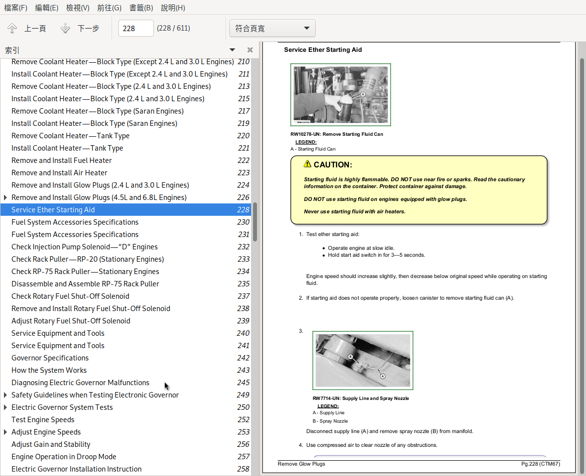
Service Ether Starting Aid
Fuel System Accessories Specifications
Fuel System Accessories Specifications
Check Injection Pump Solenoid—“D” Engines
Check Rack Puller—RP-20 (Stationary Engines)
Check RP-75 Rack Puller—Stationary Engines
Disassemble and Assemble RP-75 Rack Puller
Check Rotary Fuel Shut-Off Solenoid
Remove and Install Rotary Fuel Shut-Off Solenoid
Adjust Rotary Fuel Shut-Off Solenoid
Service Equipment and Tools
Service Equipment and Tools
Governor Specifications
How the System Works
Diagnosing Electric Governor Malfunctions
Safety Guidelines when Testing Electronic Governor
Safety
Prevention of Damage
Electric Governor System Tests
Test No. 1
Test No. 2
Test No. 3
Test Engine Speeds
Adjust Engine Speeds
Idle Speed Between 700—900 rpm
Idle Speed Below 700 rpm or Above 900 rpm
Adjust Gain and Stability
Engine Operation in Droop Mode
Electric Governor Installation Instruction
Connect Electric Governor Wiring Harness
Remove Electric Governor
Service Magnetic Pickup
Service Equipment and Tools
Service Equipment and Tools
Fuel Supply Pump Specifications
Relieve System Pressure
Test John Barnes Fuel Supply Pump Pressure—8955T, A Engine Serial No. ( —3076)
Adjust John Barnes Fuel Supply Pump Relief Valve—8955T, A Engines Serial No. ( —3076)
Remove John Barnes Electric Fuel Supply Pump—8955 Engine Serial No. ( —3076)
Remove Pressure Regulating Valve
Install Pressure Regulating Valve
Repair Fuel Pump
Install John Barnes Fuel Supply Pump—8955 Engine Serial No. ( —3076)
Test Bosch Fuel Supply Pump Pressure—8955T, A Engine Serial No. (3077— )
Replace Bosch Fuel Supply Pump—8955T, A Engines Serial No. (3077— )
Service Equipment and Tools
Service Equipment and Tools
Other Material
Engine Cooling System Specifications
Test Charge Air Cooler
Remove and Install Charge Air Cooler
Remove and Install Coolant Temperature Sensor
Pressure Test Cooling System and Radiator Cap
Test Radiator Cap
Test Cooling System
Radiator and Hoses
Install Radiator Fan—Blower and Suction Types
Check Fan and Alternator Belts
Remove and Install Fan and Alternator Belts
Manual Belt Tensioner Adjustment
Manual Belt Tensioner Adjustment Using Belt Tension Tool (Alternate Method For Engines Without Auxiliary Drive)
Check Automatic Belt Tensioner Spring Tension and Belt Wear
Check Belt Wear
Check Upper Tensioner Spring Tension
Check Lower Tensioner Spring Tension (If equipped)
Adjust Fan and Alternator Belts
Essential Tools
Essential Tools
Service Equipment and Tools
Rockford/Twin Disc Rear Power Take-Off Specifications
General Information
Diagnosing Malfunctions
Remove Power Take-Off
Power Take-Off Exploded View
Disassemble Power Take-Off
Remove Yoke
Disassemble Clutch Assembly (Early Version)
Disassemble Clutch Assembly (Later Version)
Inspect Power Take-Off Parts
Assemble Drive Shaft and Bearings—Side-Load Application
Assemble Drive Shaft and Bearings—In-Line Application
Install Yoke
Check and Adjust Drive Shaft End Play
Assemble Clutch Unit (Early Version)
Assemble Clutch Unit (Late Version)
Install Clutch Unit
Check Flywheel Housing Face Run-Out
Check Flywheel Face Flatness
Check Pilot Bearing Bore
Inspect Drive Ring
Install Power Take-Off
Check PTO Clutch Adjustment—Early Version
Check PTO Clutch Adjustment—Late Version
Special Or Essential Tools
Special Or Essential Tools
Other Material
Rear Power Take-Off Specifications For 8.1L/9.0L and 12.5L/13.5L Engines With Primary and Auxiliary Pump Drives (Double Pump)
Rear Power Take-Off Specifications For 8.1L/9.0L and 12.5L/13.5L Engines With Primary Pump Drive (Single Pump)
General Information
Theory of Operation
Lubrication Passages
Photo Disclosure
Remove Rear PTO
Disassemble Auxiliary Pump Group
Disassemble Primary Pump Group
Disassemble Auxiliary Idler Shaft Group
Single Pump Application
Double Pump Application
Disassemble Primary Idler Shaft Group
Inspect and Assemble Engine Rear Power Take-Off Housing Group
Flywheel Access Cover Plate
Primary Idler Shaft Group
Assemble Primary Idler Shaft Group
Auxiliary Idler Shaft Group
Assemble Auxiliary Idler Shaft Group
Single Pump Application
Double Pump Application
Auxiliary Pump Access Cover Plate (For Single Pump Application Only)
Primary Pump Group
Assemble Primary Pump Group
Auxiliary Pump Group
Assemble Auxiliary Pump Group (Double Pump Rear Power Take-Off)
Input Gear Assembly and Seal Retainer Group
Install Rear PTO
Essential Tools
Essential Tools
Front Power Take-Off Specifications
Checking Vibration Damper or Pulley (Engine With Front PTO)
Remove Vibration Damper or Pulley (Engine With Front PTO)
Install Vibration Damper or Pulley (Engine With Front PTO)
Installing PTO Drive Gear (Crankshaft Gear-Driven PTO)
Remove and Install Front PTO Clutch Adapter (Electric)
Remove and Install Front PTO Clutch Adapter (Mechanical)
Service Equipment and Tools
Service Equipment and Tools
Other Material
Auxiliary Drive, 6076 (500000— ) Specifications
Auxiliary Drive General Information
Remove Right-Hand Output Gear Assembly
Disassemble Right-Hand Output Gear Assembly
Assemble Right-Hand Output Gear Assembly
Install Right-Hand Output Gear Assembly
Remove Left-Hand Output Gear Assembly
Disassemble Left-Hand Output Gear Assembly
Assemble Left-Hand Output Gear Assembly
Remove Left-Hand Rear Adapter Housing
Remove Idler Housing and Idler Gear
Replace Idler Gear Bearing
Install Idler Housing and Idler Gear
Install Left-Hand Output Gear Assembly
Install Left-Hand Rear Adapter Housing
Auxiliary Drive (2.9 L) Specifications
Auxiliary Drive (2.9 L) Specifications
Remove and Install Right-Hand Auxiliary Drive
Auxiliary Drive (4.5 L and 6.8 L) Specifications
Auxiliary Drive (4.5 L and 6.8 L) Specifications
Remove and Install Auxiliary Drive
Remove and Install Offset Auxiliary Drive
Disassemble and Inspect Auxiliary Drive Adapter
Disassemble and Inspect Offset Auxiliary Drive Adapter
Auxiliary Drive Specifications
Auxiliary Drive Specifications
Remove Right-Hand Output Gear Assembly
Disassemble Right-Hand Output Gear Assembly
Assemble Right-Hand Output Gear Assembly
Install Right-Hand Output Gear Assembly
Remove Left-Hand Output Gear Assembly
Disassemble Left-Hand Output Gear Assembly
Assemble Left-Hand Output Gear Assembly
Remove and Install Left-Hand Rear Adapter Housing
Remove Idler Housing and Idler Gear
Replace Idler Gear Bearing
Install Idler Housing and Idler Gear
Install Left-Hand Output Gear Assembly
Auxiliary Drive Specifications
Auxiliary Drive Specifications
Remove Left-Hand Output Gear Assembly
Remove Left-Hand Rear Housing
Remove Left-Hand Aux Drive Housing from Cylinder Block
Remove Left-Hand Aux Drive Housing from Timing Gear Cover
Remove and Install Idler Gear
Remove Idler Gear
Install Idler Gear
Install Left-Hand Aux Drive Housing to Timing Gear Cover
Install Left-Hand Aux Drive Housing to Cylinder Block
Torque Left-Hand Aux Drive Assembly
Install Left-Hand Rear Housing
Install Left-Hand Output Gear Assembly
Essential Tools
Essential Tools
Auxiliary Drive (10.5 L, 12.5 L and 13.5 L) Specifications
Remove and Install Auxiliary Drive Idler Gear and Bearing
Remove and Install SAE “A” and “B” Front and SAE “B” Rear Auxiliary Drive Assembly
Essential Tools
Essential Tools
Service Equipment and Tools
Air Compressor Specifications
Air Compressor General Information
Compressor Troubleshooting Chart
Compressor Troubleshooting Chart (Continued)
Remove And Install Air Compressor (4.5 L and 6.8 L)
Remove And Install Air Compressor [6076 (S.N. 500000— ) and 8.1 L]
Remove and Install Air Compressor (10.5 L and 12.5 L)
Air Compressor Drive Gear, Remove and Install (10.5L and 12.5L)
Air Compressor Spline Drive Shaft, Remove and Install (10.5L and 12.5L)
Essential Tools
Essential Tools
Air Conditioning Specifications
Air Conditioning General Information
Proper Refrigerant Handling
R-134a Refrigerant Cautions
Air Conditioning Retrofit
System Information
Flushing:
Purging:
Evacuating:
Discharge Air Conditioning System
Flush/Clean Air Conditioning Compressor
Purge Air Conditioning System
Evacuate Air Conditioning System
Check Refrigerant Oil Charge
Determine Correct Refrigerant Oil Charge
Add Refrigerant Oil to Pressurized System
Charge Air Conditioning System
Diagnosing Air Conditioning Compressor Malfunctions
Remove and Install Air Conditioning Compressor
Test Volumetric Efficiency
Compressor Leakage Test
Disassemble and Assemble Compressor Clutch (Denso Compressor)
Check Clutch Hub Clearance
Inspect Compressor Manifold (Denso Compressor)
Disassemble, Inspect, and Assemble Compressor (Denso Compressor)
Remove and Install Compressor Relief Valve (Denso Compressor)
ctm67 - OEM Engine Accessories Component Technical Manual Main Sections
Foreword
Section : OEM Engine Accessories
Safety
General Information
Electrical System Information and Wiring Diagrams
Electrical System Diagnostics, Tests and Operation
Electrical System Repair and Adjustments
Cold Weather Starting Aids
Fuel System Accessories
UTC Electric/Isochronous Governor (8955 Engines)
Electric Fuel Supply Pump—8955 Engines
Engine Cooling System Accessories
Rear PTO - Rockford/Twin Disc
Rear PTO - John Deere
Front PTO
Auxiliary Drive, 6076 (500000— )
Auxiliary Drive (2.9 L)
Auxiliary Drive (4.5 L and 6.8 L)
Auxiliary Drive (8.1 L)
Auxiliary Drive (9.0L)
Auxiliary Drive (10.5L, 12.5L and 13.5L)
Air Compressors
Air Conditioning Compressors
John Deere OEM Engine Accessories Component Technical Manual (CTM67)
![]()