
John Deere 5055E, 5065E & 5075E Tractors Repair Service Manual (TM901319)
Complete service repair manual for John Deere 5055E, 5065E & 5075E Tractors, with all the technical information to maintain, service, and rebuild like professional mechanics.
John Deere 5055E, 5065E & 5075E Tractors workshop service repair manual includes:
* Numbered table of contents easy to use so that you can find the information you need fast.
* Detailed sub-steps expand on repair procedure information
* Numbered instructions guide you through every repair procedure step by step.
* Notes, cautions and warnings throughout each chapter pinpoint critical information.
* Bold figure number help you quickly match illustrations with instructions.
* Detailed illustrations, drawings and photos guide you through every procedure.
* Enlarged inset helps you identify and examine parts in detail.
tm901319 - John Deere 5055E, 5065E& 5075E Tractors Repair (European Edition) Technical Manual.pdf
tm901319 - John Deere 5055E, 5065E& 5075E Tractors Repair (European Edition) Technical Manual.epub
PRODUCT DETAILS:
Total Pages: 936 pages
File Format: PDF/EPUB/MOBI/AZW (PC/Mac/Android/Kindle/iPhone/iPad; bookmarked, ToC, Searchable, Printable)
Language: English
tm901319 - 5055E, 5065E And 5075E Tractors Repair Technical Manual(European Edition)
Table of Contents
Foreword
Section 10: General Information
Group 05: Safety
Recognize Safety Information
Understand Signal Words
Follow Safety Instructions
Prepare for Emergencies
Wear Protective Clothing
Protect Against Noise
Handle Fuel Safely—Avoid Fires
Fire Prevention
In Case of Fire
Avoid Static Electricity Risk When Refueling
Use Foldable ROPS and Seat Belt Properly
Stay Clear of Rotating Drivelines
Use Steps and Handholds Correctly
Read Operator’s Manuals for ISOBUS Controllers
Use Seat Belt Properly
Vibration
Operating the Tractor Safely
Avoid Backover Accidents
Limited Use in Forestry Operation
Operating the Loader Tractor Safely
Keep Riders Off Machine
Passenger Seat
Use Safety Lights and Devices
Towing Trailers/Implements Safely
Use Caution on Slopes, Uneven Terrain, and Rough Ground
Freeing a Mired Machine
Avoid Contact with Agricultural Chemicals
Handle Agricultural Chemicals Safely
Handling Batteries Safely
Avoid Heating Near Pressurized Fluid Lines
Remove Paint Before Welding or Heating
Handle Electronic Components and Brackets Safely
Practice Safe Maintenance
Avoid Hot Exhaust
Clean Exhaust Filter Safely
Work In Ventilated Area
Support Machine Properly
Prevent Machine Runaway
Park Machine Safely
Transport Tractor Safely
Service Cooling System Safely
Service Accumulator Systems Safely
Service Tires Safely
Service Front-Wheel Drive Tractor Safely
Tightening Wheel Retaining Bolts/Nuts
Avoid High-Pressure Fluids
Do Not Open High-Pressure Fuel System
Store Attachments Safely
Decommissioning — Proper Recycling and Disposal of Fluids and Components
Group 10: General Specifications
General Specifications
Overall Dimensions and Weights
Loads For Tractor
Sound Level
Ground Speed Estimates — (Sync Shuttle Transmission)
Ground Speed Estimates — (PowrReverser PowrReverser is a trademark of Deere & Company Transmission)
Correction Factors For Other Tire Sizes
Service Recommendations for O-Ring Boss Fittings
Service Recommendations for Flat Face O-Ring Seal Fittings
Metric Bolt and Screw Torque Values
Unified Inch Bolt and Screw Torque Values
Group 20: Fuel and Lubricants
Diesel Fuel
Avoid Static Electricity Risk When Refueling
Fuel Storage
Do Not Use Galvanized Containers
Fill Fuel Tank
Diesel Engine Oil — Non-Emissions Certified and Certified Tier 1 and Stage I
Diesel Engine Coolant (engine with wet sleeve cylinder liners)
Transmission and Hydraulic Oil
Grease (Specific Application)
Grease
Lubricant Storage
Group 25: Serial Number Locations
Serial Numbers
Product Identification Number
Record Engine Serial Number
Fuel Injection Pump Serial Number
Alternator Serial Number Location
Power Steering Valve Serial Number Location
Transmission Serial Number Location (9X3 TSS Transmission)
Transaxle Serial Number Location (12X12 PR Transmission)
Record Mechanical Front Wheel Drive (MFWD) Serial Number
Cab Serial Number
ROPS Serial Number
Group 30: Features and Accessories
Features and Accessories
Standard Features
Field Installed Optional Kits and Accessories
Section 20: Engine Repair
Group 05: Engine
Service Equipment and Tools
Specifications
John Deere Engine Repair
Remove Engine
Install Engine
Group 10: Cooling System
Special or Essential Tools
Specifications
Torques for Hardware
Clean Grille, Radiator, Charge Air Cooler (CAC), and Fuel Cooler (SyncShuttle)
Clean Grille, Radiator, Charge Air Cooler (CAC), Oil Cooler and Fuel Cooler (PowrReverser PowrReverser is a trademark of Deere & Company )
Remove and Inspect Radiator
Water Pump — Exploded View
Remove Water Pump
Disassemble Water Pump
Assemble Water Pump
Install Water Pump
Inspect Thermostat
Cooling System Deaeration
Check Fan/Alternator Belt Tension
Install Radiator
Replace Thermostat
Section 30: Fuel and Air Intake System Repair
Group 05: Fuel System
Special or Essential Tools
Self-Manufactured Tool Template For Front Plate Replacement
Torques For Hardware
Injection Pump, Nozzle and Governor Repair
Remove, Inspect and Install Fuel Tank
Replace Fuel Filter
Remove and Install Fuel Filter/Primer Pump Assembly
Group 10: Air Intake and Exhaust System
Remove, Inspect, and Install Air Cleaner Elements
Check Air Inlet Pipe
Remove Turbocharger
Exhaust Manifold Inspection
Install Turbocharger
Turbocharger Break-In
Group 15: Speed Control Linkage
Inspect and Repair Speed Control Linkage
Section 40: Electrical Repair
Group 05: Battery, Starter and Alternator
Starter Repair—Use CTM
Remove and Install Battery (Cab)
Remove and Install Battery(IOOS)
Remove and Install Starter
Alternator/Regulator Repair—Use CTM
Replace Alternator/Regulator
Group 10: Electrical System Components
Service Equipment and Tools
Other Material
Replace Air Filter Restriction Sensor
Replace Coolant Temperature Sender
Replace Engine Speed Sensor
Replace Engine Oil Pressure Sensor
Replace Key Switch (CAB)
Replace Key Switch (IOOS)
Replace Light Switch
Replace Beacon Lamp Switch (CAB)
Replace Beacon Lamp Switch (IOOS)
Replace Turn Signal Switch (CAB)
Replace Turn Signal Switch (IOOS)
Replace Wiper Control Switch
Remove And Install Wiper Motor
Remove and Replace EH Directional Reverser Lever (If Equipped)
Replace Instrument Cluster
Replace Instrument Panel (CAB)
Replace Instrument Panel (IOOS)
Replace Starter Relay
Replace Rear PTO ON/OFF Switch (PowrReverser PowrReverser is a trademark of Deere & Company )
Remove and Install Rear PTO Switch (TSS Transmission)—Cab
Replace Electro-Hydraulic Control (EHC) Unit—Cab (If Equipped)
Replace Clutch Enable Solenoid Valve—PR Transmission
Replace Transmission Reverse Solenoid Valve—PR Transmission
Replace Transmission Forward Solenoid Valve—PR Transmission
Replace Clutch Pedal Position Sensor (PR Transmission)
Replace Seat Switch (Cab)
Replace Neutral Start Switch
Replace Park Pawl Switch
Replace MFWD Switch
Replace 7 Pin Connector
Replace Park Brake Switch
Replace Horn
Replace Fuel Level Sender
Replace Rotating Beacon Lamp
Group 15: Wiring Harness
Special or Essential Tools
Service Parts Kits
Remove Connector Body from Blade Terminals
Replace WEATHER PACK WEATHER PACK is a trademark of Packard Electric. Connector
Install WEATHER PACK WEATHER PACK is a trademark of Packard Electric. Contact
Replace Battery Positive Cable (CAB)
Replace Battery Positive Cable (IOOS)
Replace Engine Power Cable
Replace Hood Wiring Harness
Replace Beacon Lamp Wiring Harness (CAB)
Replace Front Windshield Wiper Harness (Cab)
Replace Engine Wiring Harness
Replace Console Wiring Harness (9x3 TSS Transmission)
Replace Console Wiring Harness (CAB) (12x12 PR Transmission)
Replace Console Wiring Harness (IOOS — 12x12 PowrReverser™ Transmission)
Replace Rear Wiring Harness (9x3 TSS Transmission)
Replace Rear Wiring Harness (CAB) (12x12 PR Transmission)
Replace Rear Wiring Harness (IOOS) (12x12 PR Transmission)
Replace Transmission Harness—Cab (12x12 PowrReverser™ Transmission)
Replace Transmission Harness—IOOS (12x12 PowrReverser™ Transmission)
Replace Roof Harness—Cab
Replace 7-Pin Connector Wiring Harness (CAB)
Replace 7-Pin Connector Wiring Harness (IOOS)
Section 50: Power Train Repair (12x12 PR Transmission)
Group 05: Clutch Housing
John Deere Transmission Repair — Use CTM
Specifications
Separate Engine from Clutch Housing (PR)
Install Engine to Clutch Housing (PR)
Remove, Inspect, and Repair Clutch Pedal and Linkage (PR)
Group 10: Clutch Assembly
Specifications
Adjust Clutch Pedal and Linkage
John Deere Transmission Repair — Use CTM
Group 15: Transmission
Other Material
Specifications
John Deere Transmission Repair — Use CTM
Inspect and Repair Gear Shift Lever
Inspect and Repair Range Shift Lever
Group 21: Rear PTO
Other Material
Specifications
John Deere Transmission Repair — Use CTM
Group 26: Differential
Essential Tools
Service Equipment and Tools
Other Material
Specifications
Service Parts Kits
John Deere Transmission Repair — Use CTM
Group 30: Final Drives
Service Equipment and Tools
Other Material
Specifications
John Deere Transmission Repair — Use CTM
Group 35: Mechanical Front Wheel Drive
Mechanical Front Wheel Drive – If Equipped—Summary of References
Service Equipment and Tools
Essential Tools
Other Material
Specifications
MFWD Axle Repair — Use CTM
MFWD Dropbox Repair—Use CTM
Remove, Inspect and Install MFWD Drive Shaft(PR)
Remove and Install MFWD Axle Housing Assembly(PR)
Remove, Inspect and Install MFWD Axle Supports (Without Paddy Seal)(PR)
Section 51: Power Train Repair (9x3 TSS Transmission)
Group 05: Clutch Housing
John Deere Transmission Repair — Use CTM
Service Equipment and Tools
Other Material
Essential Tools
Specification
Separate Engine from Clutch Housing (TSS)
Install Engine to Clutch Housing (TSS)
Inspect and Repair Clutch Pedal and Linkage (TSS)
Group 10: Clutch Assembly
Specification
Traction Clutch Finger Adjustment
PTO Clutch Finger Adjustment
John Deere Transmission Repair — Use CTM
Group 15: Transmission
Specifications
John Deere Transmission Repair — Use CTM
Inspect and Repair Gear Shift Lever
Inspect and Repair Range Shift Lever
Group 21: Rear PTO
Other Material
Specifications
John Deere Transmission Repair — Use CTM
Remove, Inspect and Install Rear PTO Lever and Linkage
Group 26: Differential
John Deere Transmission Repair — Use CTM
Group 30: Final Drives
Service Equipment and Tools
Other Material
Specifications
Remove and Install Final Drive Assembly
Remove and Inspect Planetary Drive Assembly
Install Planetary Drive Assembly
Remove, Inspect, and Install Axle Shaft Assembly
Group 35: Mechanical Front Wheel Drive
Mechanical Front Wheel Drive – If Equipped—Summary of References
Service Equipment and Tools
Essential Tools
Other Material
Specifications
MFWD Axle Repair—Use CTM
Inspect and Repair MFWD Lever and Linkage
Remove and Install MFWD Drop Gearbox
Disassemble and Inspect MFWD Drop Gear box
MFWD Drop Gearbox Cross Section
Assemble MFWD Drop Gearbox
Remove, Inspect and Install MFWD Drive Shaft
Remove and Install MFWD Axle Housing Assembly
Remove, Inspect and Install MFWD Axle Supports (Without Paddy Seal)
Section 60: Steering and Brake Repair
Group 05: Steering Repair
Other Material
Specification
Service Parts Kits
Remove and Install Steering Wheel
Remove and Install Tilt/Telescoping Steering Column
Remove and Install Steering Column and Valve
Disassemble and Inspect Steering Valve - Sauer Danfoss
Assemble Steering Valve - Sauer Danfoss
Remove and Install Steering Cylinder— MFWD Axle
Disassemble, Inspect, and Assemble Steering Cylinder—MFWD Axle
Remove, Inspect and Install Tie Rod Assembly—MFWD Axle
Inspect and Replace Steering Hydraulic Lines
Group 10: Brake Repair
Service Equipment and Tools
Other Material
Specification
Remove and Install Brake Valve and Pedals
Disassemble and Inspect Brake Pedals and Valve
Brake Valve Cross Section
Assemble Brake Valve
Remove and Inspect Brakes
Install Brakes
Inspect and Replace Brake Hydraulic Lines
Section 70: Hydraulic Repair
Group 05: Hydraulic Pump and Filter
Essential Tools
Specifications
Service Parts Kits
Remove, Inspect, and Install Hydraulic Oil Pick-Up Screen
Remove and Install Hydraulic Pump
Remove Hydraulic Pump External Components
Disassemble and Inspect Hydraulic Pump
Assemble Hydraulic Pump
Install Hydraulic Pump External Components
Remove and Install Hydraulic Oil Filter/Manifold
Inspect and Replace Hydraulic Supply and Suction/Return Lines
Group 10: JD Rockshaft
Other Material
Specification
Inspect and Repair Rockshaft Control Lever Assembly
Inspect and Repair Rockshaft Control Linkage
Inspect and Repair Draft Sensing Support Assembly
Replace Main Relief Valve
Replace Rockshaft Surge Relief Valve
Remove, Inspect, and Install Rate-of-Drop Valve
Replace Rockshaft Control Valve
Remove and Install Rockshaft Case
Remove, Inspect, and Install Rockshaft Lift Arms
Remove, Inspect, and Install Rockshaft Piston and Cylinder
Group 15: Selective Control Valve (SCV)
Specification
Inspect and Repair SCV Lever and Linkage
Remove and Install EATON Selective Control Valve
Remove and Install Rear Coupler Bracket
Remove and Install SCV Oil Lines
Disassemble, Inspect and Assemble Dual Mid-Mount Selective Control Valve (SCV)
Remove and Install EQRL Motor (If Equipped)
Section 80: Miscellaneous Repair
Group 05: Front Axle
Specification
Remove and Install Front Axle — MFWD
Group 10: Wheels
Specifications
Remove and Install Front or Rear Wheels
Inspect and Replace Front Wheel Bearings
Tighten Bolts—Rear Axle (M-20 Bolt)
Tighten Nuts—Front Axle (MFWD)
Group 15: 3-Point Hitch
Specifications
Inspect and Repair Fixed Draft Links
Inspect and Repair Lift Link (If Equipped)
Inspect and Repair Lift Link (If Equipped)
Inspect and Repair Adjustable Lift Link (If Equipped)
Inspect and Repair Adjustable Lift Link (If Equipped)
Inspect and Repair Center Link
Remove and Install Wagon Hitch and Support
Remove and Install EQRL Motor
Group 20: Hood
Specification
Remove and Install Hood
Group 25: Ballast
Specifications
Remove and Install Front Ballast
Remove and Install Rear Ballast
Section 90: Operator Station Repair (CAB)
Group 05: Seat and Support
Remove and Install Seat and Support (Cab)
Group 10: Control Console and Panel
Specifications
Remove and Install Right-Side Control Console
Remove and Install Left-Side Control Console
Remove and Install Center Control Console (TSS Transmission)
Remove and Install Center Control Console (PR Transmission)
Group 20: Cab Components
Essential Tools
Service Equipment and Tools
Other Material
Specifications
Remove, Inspect, and Install Cab Interior Recirculating Air Filters
Remove, Inspect, and Install Exterior Cab Intake Air Filter
Remove and Install Headliner
Remove and Install Cowl Cover
Remove and Install Left-Side Upholstery
Remove and Install Right-Side Upholstery
Remove and Install Windshield
Remove and Install Front Lower Windows
Remove and Install Rear Lower Window
Remove and Install Rear Upper Window
Remove and Install Side Windows
Remove and Install Cab Doors
Remove and Install Inner Roof for Air Conditioning Housing Repair ( -XXXXXX)
Remove and Install Inner Roof for Air Conditioning Housing Repair (XXXXXX- )
Remove Cab ( -XXXXXX)
Remove Cab (XXXXXX- )
Install Cab ( -XXXXXX)
Install Cab (XXXXXX- )
Group 30: Air Conditioning System
Essential Tools
Service Equipment and Tools
Other Material
Specifications
Adjust A/C Temperature Control Switch
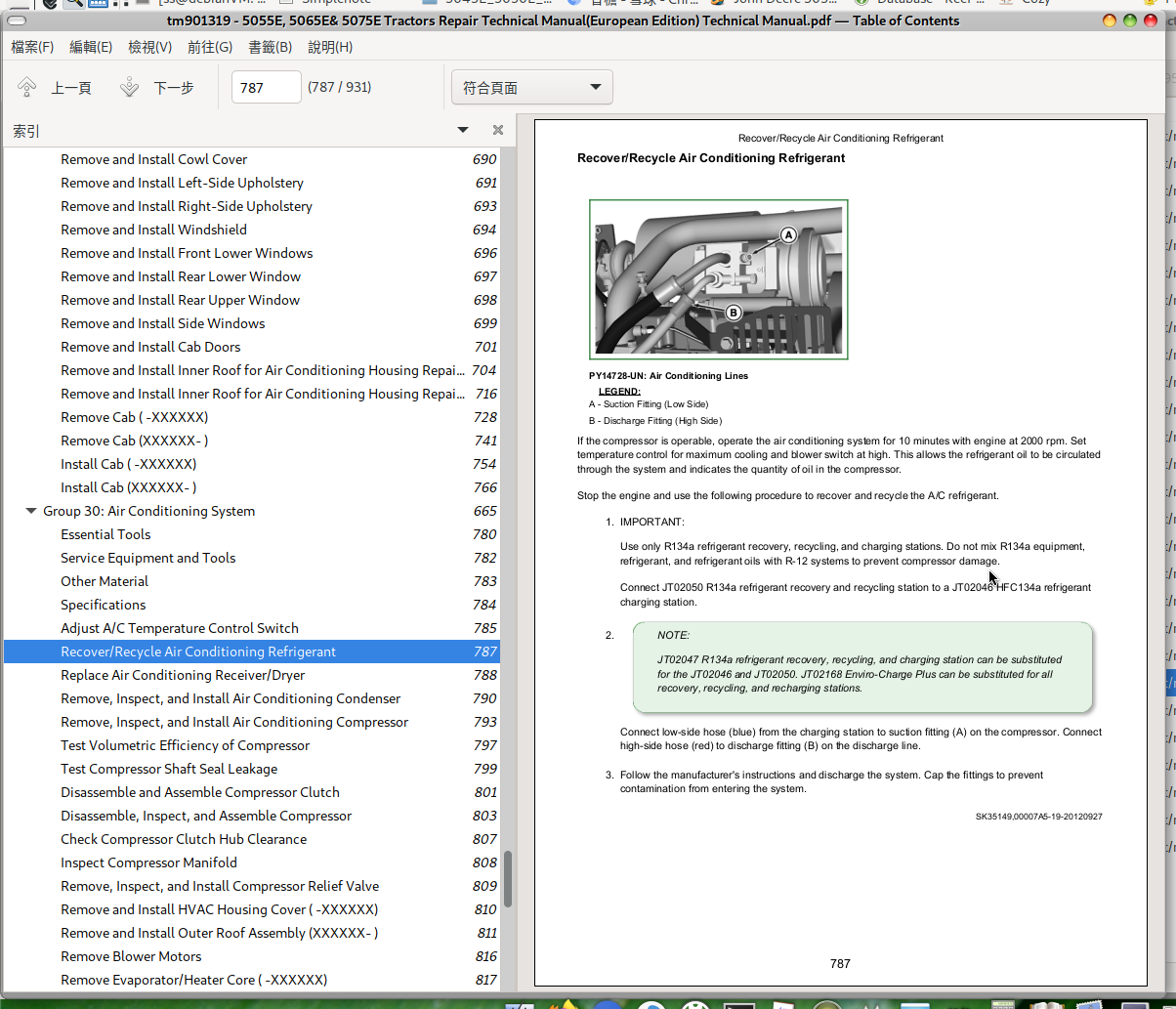
Recover/Recycle Air Conditioning Refrigerant
Replace Air Conditioning Receiver/Dryer
Remove, Inspect, and Install Air Conditioning Condenser
Remove, Inspect, and Install Air Conditioning Compressor
Test Volumetric Efficiency of Compressor
Test Compressor Shaft Seal Leakage
Disassemble and Assemble Compressor Clutch
Disassemble, Inspect, and Assemble Compressor
Check Compressor Clutch Hub Clearance
Inspect Compressor Manifold
Remove, Inspect, and Install Compressor Relief Valve
Remove and Install HVAC Housing Cover ( -XXXXXX)
Remove and Install Outer Roof Assembly (XXXXXX- )
Remove Blower Motors
Remove Evaporator/Heater Core ( -XXXXXX)
Remove Evaporator/Heater Core (XXXXXX- )
Leak Test Evaporator/Heater Core
Install Evaporator/Heater Core ( -XXXXXX)
Install Evaporator/Heater Core (XXXXXX- )
Service Expansion Valve
Expansion Valve Bench Test
Refrigerant Oil Information
Check Compressor Oil Charge
Determine Correct Refrigerant Oil Charge
Add Refrigerant Oil to System
System Information
Flush Air Conditioning System
Evacuate Air Conditioning System
Charge Air Conditioning System
Group 35: Heating System
Adjust Heater Temperature Control Cable
Replace Heater Temperature Control Cable ( -XXXXXX)
Replace Heater Temperature Control Cable (XXXXXX- )
Remove Heater Control Valve ( -XXXXXX)
Remove Heater Control Valve (XXXXXX- )
Leak Test Heater Control Valve
Install Heater Control Valve ( -XXXXXX)
Install Heater Control Valve (XXXXXX- )
Section 91: Operator Station Repair (IOOS)
Group 05: Seat and Support
Remove and Install Seat and Support (IOOS)
Disassemble, Inspect and Assemble Seat and Seat Switch
Group 10: Control Console and Panel
Remove and Install Center Control Console
Remove and Install Right-Side Control Console (IOOS)
Remove and Install EQRL Switch (If Equipped)
Remove and Install Secondary Brake Lever (If Equipped)
Group 11: Roll-Gard™
Specification
Remove ROLL-GARD™
Install ROLL-GARD™
ROPS Serial Number
Group 20: Operator Station
Specification
Remove Operator Platform (IOOS)
Install Operator Platform (IOOS)
Remove and Install Left and Right Side Steps
Remove Center Console Assembly
Install Center Console Assembly
Group 25: Fenders
Remove and Install Fenders
John Deere 5055E, 5065E & 5075E Tractors Repair Service Manual (TM901319)
![]()