
Isuzu Engine 6WF1-TC, 6WG1, 6WG1T, 6WG1-TC, 6SD1T, 6RB1, 6RB1T, AH-6UZ1, AA-6SD1T Models Service Manual
Complete repair service manual for Isuzu Engines 6WF1-TC, 6WG1, 6WG1T, 6WG1-TC, 6SD1T, 6RB1, 6RB1T, AH-6UZ1, AA-6SD1T Models, with all the technical information to maintain, diagnose, repair, and service like professional mechanics.
Isuzu Engine 6WF1-TC, 6WG1, 6WG1T, 6WG1-TC, 6SD1T, 6RB1, 6RB1T, AH-6UZ1, AA-6SD1T Modelsworkshop service & repair manual includes:
* Numbered table of contents easy to use so that you can find the information you need fast.
* Detailed sub-steps expand on repair procedure information
* Numbered instructions guide you through every repair procedure step by step.
* Troubleshooting and electrical service procedures are combined with detailed wiring diagrams for ease of use.
* Notes, cautions and warnings throughout each chapter pinpoint critical information.
* Bold figure number help you quickly match illustrations with instructions.
* Detailed illustrations, drawings and photos guide you through every procedure.
* Enlarged inset helps you identify and examine parts in detail.
MANUAL LIST:
6WG1E00 - Isuzu 6WG1 Engine Service Manual (Hitachi).pdf
9-54850 - Isuzu 6WG1T Engine Service Manual (CNH Case).pdf
9-54870_EN - Isuzu Engines 6SD1T Service Manual.pdf
9806-2166 - Isuzu 6RB1, 6RB1T Model Industrial Diesel Engine Workshop Manual.pdf
IDE-2392 - Isuzu AA-6SD1T Model Industrial Diesel Engine Workshop Manual.pdf
IDE-2440 - Isuzu AH-6UZ1 Model Industrial Diesel Engine Workshop Manual.pdf
PRODUCT DETAILS:
Total Pages: 3,483 pages
File Format: PDF (Windows & Mac & Linux)
Language: English
...
6WFGCEDG2-WE-0661 - Isuzu C&E SERIES ENGINE CONTROL SYSTEM (6WF1-TC, 6WG1-TC (Common Rail) models) WORKSHOP MANUAL................1
TOP................0
Engine Control System (6WF1-TC,6WG1-TC(Common Rail))................5
Engine Control System................6
Precautions for servicing................6
Explanation of Functions and Operations................8
Parts layout diagram................35
Circuit Diagram................40
Connector List................62
Fault diagnosis process................73
Breakdown diagnosis using the scan tool.................79
Function Inspection List................92
Oral consultation................93
On-Board Diagnosis (OBD) System Check................95
Checking the MIL (check engine lamp) lighting circuit system (MIL does not turn ON)................98
Checking the MIL (check engine lamp) flashing control system (MIL does not flashing)................101
Checking the Scan Tool Circuit System................104
Checking the starting system................107
Checking the fuel system................110
Checking the intake air system................114
Checking the exhaust system................116
Checking the EGR................120
Checking the engine control module (ECM) power supply and ground circuit................123
Checking the PTO................126
Table of diagnostics codes................130
DTC P0014 (Flash code 14)................141
DTC P0015 (Flash code 15)................145
DTC P0022 (Flash code 22)................149
DTC P0023 (Flash code 23)................153
DTC P0024 (Flash code 24)................157
DTC P0025 (Flash code 25)................161
DTC P0032 (Flash code 32)................166
DTC P0033 (Flash code 33)................170
DTC P0035 (Flash code 35)................172
DTC P0042 (Flash code 42)................174
DTC P0051 (Flash code 51)................177
DTC P0071 (Flash code 71)................179
DTC P0072 (Flash code 72)................181
DTC P0115 (Flash code 115)................183
DTC P0118 (Flash code 118)................187
DTC P0151 (Flash code 151)................193
DTC P0158 (Flash code 158)................199
DTC P0159 (Flash code 159)................203
DTC P0211 (Flash code 211)................207
DTC P0217 (Flash code 217)................210
DTC P0218 (Flash code 218)................213
DTC P0226 (Flash code 226)................216
DTC P0227 (Flash code 227)................221
DTC P0242 (Flash code 242)................226
DTC P0245 (Flash code 245)................230
DTC P0247 (Flash code 247)................234
DTC P0248 (Flash code 248)................237
DTC P0271 (Flash code 271)................240
DTC P0272 (Flash code 272)................244
DTC P0273 (Flash code 273)................248
DTC P0274 (Flash code 274)................252
DTC P0275 (Flash code 275)................256
DTC P0276 (Flash code 276)................260
DTC P0277 (Flash code 277)................264
DTC P0278 (Flash code 278)................267
DTC P0411 (Flash code 411)................270
DTC P0412 (Flash code 412)................274
DTC P0413 (Flash code 413)................278
DTC P0416 (Flash code 416)................282
DTC P0418 (Flash code 418)................285
DTC P0421 (Flash code 421)................288
DTC P0424 (Flash code 424)................290
DTC P0441 (Flash code 441)................293
DTC P0442 (Flash code 442)................297
DTC P0446 (Flash code 446)................301
DTC P0447 (Flash code 447)................306
DTC P0448 (Flash code 448)................311
DTC P0449 (Flash Code 449)................316
DTC P0518(Flash Code 518)................321
DTC P0543(Flash Code 543)................323
Symptom List................325
Engine Stall................326
Engine hunting, rough idle................329
Lack of power, slugginess or hesitation................333
Excessive white smoke................336
Excessive black smoke................338
Idling revolutions cannot be adjusted................341
Idling revolutions cannot be adjusted down................343
Special tool................346
Programming................347
Explanation of Functions and Operations................347
Programming................348
Special tool................358
6WG1E00 - Isuzu 6WG1 Engine Service Manual (Hitachi)................361
Engine Manual(1/2)................361
Introduction................362
General Contents................364
Control System................366
Engine Control (Electronic control fuel injection system (Common rail type))................366
How to use this manual................368
Table of abbreviation................369
List of parts according to engine control specifications................370
About colors of wirings................371
About wiring diagrams................372
How to read trouble diagnosis section................373
Precautions on Service Work................375
Procedure of trouble diagnosis................376
Information:................377
Interview................378
Pre-inspection................380
Information:................380
Trouble Diagnosis................380
Description of terms................380
How to read DTC................381
Confirmation after repair................383
List of final check items................383
How to clear DTC................384
Trouble diagnosis with scan tool................385
About scan tool display................386
How to use trouble diagnosis-related tool................390
How to use Tech2................390
Components of Tech2................390
Each part of Tech2................391
Precautions on handling Tech2................392
Power supply................394
Check items before use................395
How to connect Tech2................395
Operation procedure................396
List of functions of Tech2................398
Diagnostic procedure................399
DTC application menu display screen................401
Data Display................402
Snapshot................403
Actuator test................407
Injector balance test................408
View captured data.................410
Tool options................412
Rewrite setting of Q adjust correction data by Tech2................413
Injector ID code (No. 1 cylinder - No. 6 cylinder) registration setting using Tech2................420
ID code upload (Tech2)................428
ID code download (Tech2)................430
How to use TIS 2000................433
TIS 2000 installation procedure................433
How to display snapshot................435
Software download................440
How to Inspect Injector................443
How to use injector checker................443
Components of injector checker................443
Method to identify using non-contact infrared thermometer................447
How to use flash tool................449
Refer to related document.................449
How to use breaker box................450
Breaker box inspection procedure................450
How to connect breaker box................450
Example of use for breaker box................451
Engine Control System................453
Description of function and operation................453
About engine control (common rail) system................453
System control schematic diagram................453
Table of Input/Output................455
Electronic control fuel injection system (Common rail type)................455
System schematic diagram................456
Fuel system................457
EGR (Exhaust gas recirculation)................457
Idling control................459
Speed limit control................459
Engine speed output to tachometer................460
Preheating control................461
Engine Control Module (ECM)................461
Engine component location diagram................463
Supply pump................464
PCV (pressure control valve)................464
Fuel temperature (FT) sensor................465
G sensor................465
Common rail................466
Flow damper................466
Pressure limiter................467
Common rail pressure sensor................467
Injector................468
Engine coolant temperature (ECT) sensor................468
Crankshaft position (CKP) sensor................469
Engine oil pressure sensor................469
Accelerator position (AP) sensor................470
Intake air temperature (IAT) sensor................470
EGR position sensor................470
Boost pressure sensor................471
Boost temperature sensor................472
Diagnosis lamp................472
DLC (data link connector)................472
Diagnostic switch................472
Memory clear switch................472
Mode selector switch (1, 2, 3)................472
Wiring diagram of engine control module (ECM)................473
Pin arrangement of engine control module (ECM)................474
Circuit diagram................478
Main relay circuit................478
Starter for ECM control, glow circuit................479
Starter for safety relay, glow circuit................480
CAN, GND, DLC circuits................481
Indicator lamp, tachometer circuit................482
Injector circuit................483
PCV circuit................484
CKP sensor, vehicle speed sensor, fuel temperature sensor, engine coolant temperature sensor, engine oil pressure sensor circuit................485
Boost temperature sensor, boost pressure sensor circuit................486
G sensor, common rail pressure sensor, EGR circuit................487
Accelerator position sensor, barometric pressure sensor, intake air temperature sensor circuit................488
Idling selector switch, idle up switch, idle down switch, mode map switch circuit................489
Memory clear switch, engine stop switch circuit................490
Engine harness location................491
H94/H95 connector................496
Connector list................497
List of function checks................500
OBD system check................501
Diagnosis lamp illumination circuit system check................503
Diagnosis lamp blinking circuit system check................505
Scan tool power supply circuit system check................508
Scan tool communication circuit system check................510
Starting circuit system check................513
Starting system check................519
Fuel system check................522
Intake system check................525
Exhaust system check................526
EGR control system check................527
QOS system check................530
List of diagnostic trouble code................535
DTC: P0088 (Flash code 118) Common rail pressure is abnormally high (1st or 2nd stage)................548
DTC: P0089 (Flash code 151) Common rail pressure fault (Excessive pressure feed in supply pump)................553
DTC: P0091/P1291 (Flash code 247/248) PCV circuit fault (PCV1 open circuit or GND short circuit / PCV2 open circuit or GND short circuit)................558
DTC: P0092/P1292 (Flash code 217/218) PCV circuit fault (PCV1+B short circuit / PCV2+B short circuit / PCV2+B short circuit)................564
DTC: P0107 (Flash code 71) Barometric pressure sensor circuit input is low (open circuit or ground short)................569
DTC: P0108 (Flash code 71) Barometric pressure sensor circuit input is high (+5V short)................576
DTC: P0112 (Flash code 22) Intake air temperature sensor fault (low voltage fault, GND short, short, short circuit)................583
DTC: P0113 (Flash code 22) Intake air temperature sensor fault (high voltage fault, open circuit or short to power supply circuit)................589
DTC: P0117 (Flash code 23) Engine coolant temperature sensor fault (low voltage fault, GND short, short circuit)................597
DTC: P0118 (Flash code 23) Engine coolant temperature sensor input is high (open circuit or short to power supply)................603
DTC: P0182 (Flash code 211) Fuel temperature sensor fault (low voltage fault, GND short)................611
DTC: P0183 (Flash code 211) Fuel temperature sensor fault (high voltage fault, open circuit or short to power supply circuit)................617
DTC: P0192 (Flash code 245) Common rail pressure sensor fault (low voltage fault, short circuit)................625
DTC: P0193 (Flash code 245) Common rail pressure sensor fault (high voltage fault, open circuit)................631
DTC: P0201 (Flash code 271) Open circuit in injection nozzle #1 drive system................638
DTC: P0202 (Flash code 272) Open circuit in injection nozzle #2 drive system................643
DTC: P0203 (Flash code 273) Open circuit in injection nozzle #3 drive system................648
DTC: P0204 (Flash code 274) Open circuit in injection nozzle #4 drive system................653
DTC: P0205 (Flash code 275) Open circuit in injection nozzle #5 drive system................658
DTC: P0206 (Flash code 276) Open circuit in injection nozzle #6 drive system................663
DTC: P0219 (Flash code 543) Overrun................668
DTC: P0237 (Flash code 32) Boost sensor pressure fault (low voltage fault, open circuit)................670
DTC: P0238 (Flash code 32) Boost pressure sensor fault (high voltage fault, short to power supply circuit, ground open circuit)................677
DTC: P0335 (Flash code 15) Crank sensor fault (no signal)................684
DTC: P0336 (Flash code 15) Crank sensor fault (signal fault)................690
DTC: P0340 (Flash code 14) G sensor fault (no signal)................696
DTC: P0341 (Flash code 14) G sensor fault (signal fault)................702
DTC: P0380 (Flash code 66) Glow relay circuit fault................708
DTC: P0381 (Flash code 67) Glow plug lamp circuit fault................713
DTC: P0487 (Flash code 44) EGR position sensor fault................718
DTC: P0488 (Flash code 45) EGR valve control fault................724
DTC: P0522 (Flash code 294) Engine oil pressure sensor fault (low voltage fault, open circuit, ground short)................730
DTC: P0523 (Flash code 295) Engine oil pressure sensor fault (high voltage fault, short to power supply, ground short)................736
DTC: P0601 (Flash code 53) ROM fault................744
DTC: P0603 (Flash code 54) EEPROM fault................746
DTC: P0606 (Flash code 51/52) CPU fault................748
DTC: P0611 (Flash code 34) Charge circuit fault (bank 1)................750
DTC: P0612 (Flash code 34) Charge circuit fault (bank 2)................753
DTC: P0615 (Flash code 19) Starter cut relay circuit fault................756
DTC: P0650 (Flash code 77) Diagnosis lamp circuit fault................762
DTC: P1093 (Flash code 227) No pump pressure feed (2nd stage)................767
DTC: P1094 (Flash code 226) No pump pressure feed (1st stage)................776
DTC: P1095 (Flash code 225) Pressure limiter open................785
DTC: P1112 (Flash code 295) Boost temperature sensor fault (low voltage fault, ground short)................794
DTC: P1113 (Flash code 295) Boost temperature sensor fault (high voltage fault, open circuit, short to power supply circuit)................802
DTC: P1173 (Flash code 542) Overheat................809
DTC: P1225 (Flash code 31) Idle UP/DOWN switch fault................815
DTC: P1261 (Flash code 158) Injection nozzle common 1 drive system fault................819
DTC: P1262 (Flash code 159) Injection nozzle common 2 drive system fault................829
DTC: P1271 (Flash code 24) Accelerator sensor 1-2 comparison fault................839
DTC: P1277 (Flash code 24) Accelerator sensor 1 fault (low voltage fault)................845
DTC: P1278 (Flash code 24) Accelerator sensor 1 fault (high voltage fault)................850
DTC: P1282 (Flash code 24) Accelerator sensor 2 fault (low voltage fault)................855
DTC: P1283 (Flash code 24) Accelerator sensor 2 fault (high voltage fault)................860
DTC: P1345 (Flash code 16) Cam sensor out of phase................865
DTC: P1625 (Flash code 416) Main relay fault................870
DTC: P1630 (Flash code 36) A/D conversion fault................877
DTC: P1631 (Flash code 55) Voltage fault in 5-V power supply 1................879
DTC: P1632 (Flash code 55) Voltage fault in 5-V power supply 2................882
DTC: P1633 (Flash code 55) Voltage fault in 5-V power supply 3................885
DTC: P1634 (Flash code 55) Voltage fault in 5-V power supply 4................888
DTC: P1635 (Flash code 55) Voltage fault in 5-V power supply 5................891
DTC: U2104 (Flash code 84) CAN Bus fault................894
DTC: U2106 (Flash code 85) CAN timeout fault................899
List of trouble symptom................904
Engine start failure................905
Engine stall................909
Engine hunting, rough idling................913
Engine output shortage................917
Exhaust gas contains a lot of white smoke.................922
Exhaust gas contains a lot of black smoke.................925
Noise................928
Fuel consumption deteriorates.................930
Oil consumption deteriorates.................933
Special tool................935
Difference by each machine manufacturer................936
Hitachi Construction Machinery Co., Ltd.................936
List of DTC................936
About wiring diagrams................939
Engine Manual(2/2)................944
Introduction................945
General Contents................946
Disassemble and Assemble Engine................947
General Information................947
General Information................950
Service Precautions................950
Reading the model................954
General information................954
Engine mechanical (6WG1 (Common rail))................961
6WG1-TC Engine................964
Service Precautions................964
Reading the model................965
Explanation of functions and operations................966
Functional check:................969
Main data and specifications................972
Engine accessories................974
Component parts................974
Removal................974
Installation................975
Engine exterior equipment................978
Component parts................978
Removal................981
Inspection................992
Installation................992
Torque specifications................1006
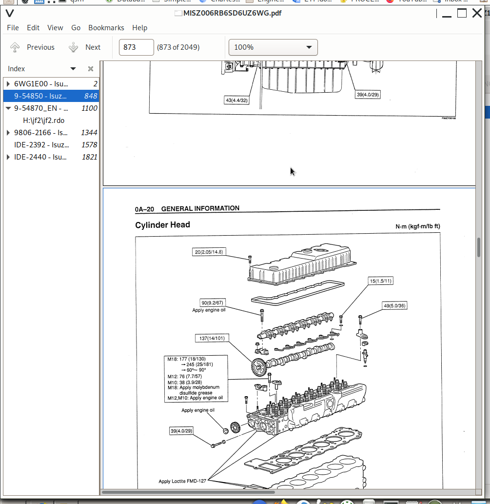
Cylinder head................1008
Component parts................1008
Removal................1008
Disassembly................1012
Inspection................1015
Assembly................1018
Installation................1023
Torque specifications................1031
Special tools................1032
Rocker arm................1033
Component parts................1033
Disassembly................1033
Inspection................1034
Assembly................1035
Camshaft................1036
Component parts................1036
Disassembly................1036
Inspection................1037
Assembly................1039
Torque specifications................1039
Timing gear................1040
Component parts................1040
Removal................1040
Inspection................1042
Disassembly................1043
Assembly................1044
Installation................1044
Torque specifications................1048
Special tools................1049
Flywheel, flywheel housing................1050
Component parts................1050
Removal................1051
Disassembly................1051
Inspection................1052
Assembly................1052
Installation................1052
Torque specifications................1055
Special tools................1056
Piston, connecting rod................1057
Component parts................1057
Removal................1057
Disassembly................1058
Inspection................1059
Assembly................1062
Installation................1065
Torque specifications................1068
Special tools................1069
Crankshaft................1070
Component parts................1070
Removal................1070
Disassembly................1071
Inspection................1072
Assembly................1075
Installation................1075
Special tools................1077
Cylinder block................1078
Component parts................1078
Disassembly................1078
Inspection................1079
Assembly................1079
Torque specifications................1082
Cooling system (6WG1 (Common rail))................1083
Cooling system................1086
Service Precautions................1086
Explanation of functions and operations................1086
Trouble shooting................1088
Engine overheats................1089
Engine overcools................1090
Main data and specifications................1090
Thermostat................1091
Component parts................1091
Removal................1091
Inspection................1092
Installation................1092
Torque specifications................1094
Special tools................1095
Water pump................1096
Component parts................1096
Disassembly................1096
Inspection................1098
Assembly................1098
Torque specifications................1101
Special tools................1102
Fuel system (6WG1 (Common rail))................1103
Fuel system................1106
Service Precautions................1106
Explanation of functions and operations................1106
Functional check:................1109
Main data and specifications................1111
Fuel filter................1112
Component parts................1112
Disassembly................1112
Inspection................1113
Assembly................1114
Electrical system (6WG1 (Common rail))................1117
Starting system................1120
Service Precautions................1120
Explanation of functions and operations................1120
Trouble shooting................1121
Even if the starter switch is switched on, the starter does not function................1122
The pinion advances but does not engage the ring gear................1123
The pinion engagement motor turns but the engine does not turn................1124
The pinion engages but the engine does not turn................1125
After starting the engine, the starter doesn't stop when the starter switch is turned off................1126
Main data and specifications................1126
Starter................1127
Component parts................1127
Disassembly................1128
Inspection................1130
Assembly................1134
Torque specifications................1137
Charging system................1138
Service Precautions................1138
Trouble shooting................1140
Does not charge at all................1141
Lack of electrical charge................1142
Overcharged................1143
Charging current is unstable................1144
Abnormal noises come from the generator................1145
Main data and specifications................1145
Generator................1146
Component parts................1146
Disassembly................1147
Inspection................1148
Assembly................1150
Functional check:................1151
Torque specifications................1152
Lubricating system (6WG1 (Common rail))................1153
Lubricating system................1156
Service Precautions................1156
Explanation of functions and operations................1156
Main data and specifications................1157
Oil filter................1159
Component parts................1159
Disassembly................1159
Assembly................1159
Special tools................1161
Oil pan, oil jet................1162
Component parts................1162
Removal................1163
Installation................1163
Torque specifications................1166
Oil pump................1167
Component parts................1167
Disassembly................1167
Inspection................1168
Assembly................1169
Torque specifications................1171
Oil cooler................1172
Component parts................1172
Disassembly................1172
Inspection................1173
Assembly................1173
Torque specifications................1175
Intake system (6WG1 (Common rail))................1177
Turbocharging system................1180
Service Precautions................1180
Explanation of functions and operations................1180
Trouble shooting................1181
If faults or vibrations occur................1182
When the turbocharger is thought to be mainly fine but output power is low................1183
Oil is leaking in the exhaust pipe or intake pipe, exhaust gas is white................1184
Main data and specifications................1184
Turbocharger................1185
Component parts................1185
Disassembly................1185
Inspection................1189
Assembly................1192
Preheating system (6WG1 (Common rail))................1197
Preheating system................1200
Service Precautions................1200
Explanation of functions and operations................1200
Functional check................1201
Trouble shooting................1202
Glow indicator lamp doesn't light................1203
Preheating doesn't function................1204
Preheating time is either too long or too short................1205
Main data and specifications................1205
9-54850 - Isuzu 6WG1T Engine Service Manual (CNH Case)................1207
9-54870_EN - Isuzu Engines 6SD1T Service Manual................1459
9806-2166 - Isuzu 6RB1, 6RB1T Model Industrial Diesel Engine Workshop Manual................1703
HB6WG-WE-1331 - Isuzu LV-Series 2013MY Engine Control System (6WG1 model) Workshop Manual................1937
HB6WGED-WE-1331 - Isuzu LV-Series 2013MY Engine Control System (6WG1 model) Workshop Manual................2213
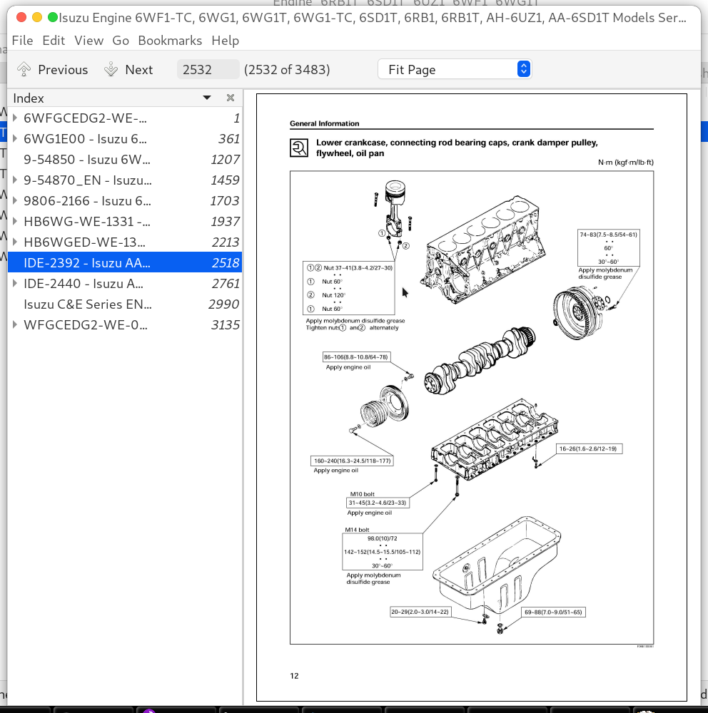
IDE-2392 - Isuzu AA-6SD1T Model Industrial Diesel Engine Workshop Manual................2518
IDE-2440 - Isuzu AH-6UZ1 Model Industrial Diesel Engine Workshop Manual................2761
General Information................2762
General Information................2763
Service Precautions................2763
Reading the Model................2768
General Information................2769
6UZ1 Engine Mechanical................2776
ISUZU Diesel Engine................2777
Service Precautions................2777
Reading the Model................2778
Explanations on Functions and Operation................2779
Function Check................2781
Specifications................2784
Engine Accessories................2786
Components................2786
Removal................2787
Installation................2787
Torque Specifications................2788
Engine Exterior Equipment................2789
Components................2789
Removal................2792
Inspection................2798
Installation................2798
Torque Specifications................2811
Cylinder Head................2814
Components................2814
Removal................2815
Disassembly................2819
Inspection................2822
Reassembly................2826
Installation................2829
Torque Specifications................2835
Rocker Arm................2836
Components................2836
Disassembly................2837
Inspection................2837
Reassembly................2838
Camshaft................2839
Components................2839
Disassembly................2840
Inspection................2840
Reassembly................2842
Torque Specifications................2842
Flywheel, Flywheel Housing and Timing Gear................2843
Components................2843
Removal................2844
Disassembly................2845
Inspection................2845
Reassembly................2847
Installation................2847
Torque Specifications................2852
Front Cover and Crankshaft................2853
Components................2853
Removal................2854
Disassembly................2855
Inspection................2856
Reassembly................2860
Installation................2861
Torque Specifications................2864
Piston, Connecting Rod................2865
Components................2865
Removal................2866
Disassembly................2867
Inspection................2867
Reassembly................2871
Installation................2873
Torque Specifications................2875
Cylinder Block................2876
Components................2876
Removal................2877
Disassembly................2877
Inspection................2877
Reassembly................2880
Installation................2881
Torque Specifications................2882
Special Tool................2883
List of Special Tool................2883
6UZ1 Cooling System................2886
Cooling System................2887
Service Precautions................2887
Explanations on Functions and Operation................2887
Function Check................2889
List of Trouble Symptom................2892
Specifications................2892
Water Pump................2893
Components................2893
Removal................2894
Disassembly................2894
Inspection................2895
Reassembly................2896
Installation................2898
Thermostat................2899
Components................2899
Removal................2900
Inspection................2900
Installation................2901
Torque Specifications................2903
Special Tool................2904
List of Special Tool................2904
6UZ1 Fuel System................2906
Fuel System................2907
Service Precautions................2907
Explanations on Functions and Operation................2907
Function Check................2911
Specifications................2912
Fuel Filter................2913
Components................2913
Disassembly................2914
Inspection................2914
Reassembly................2915
Special Tool................2917
List of Special Tool................2917
6UZ1 Electrical System................2918
Starting System................2919
Service Precautions................2919
List of Trouble Symptom................2920
Specifications................2921
Sectional View................2922
Output Characteristic................2923
Starter................2924
Components................2924
Disassembly................2925
Inspection................2926
Reassembly................2929
No Load Test................2932
Maintenance Standard................2933
Charging System................2934
Service Precautions................2934
List of Trouble Symptom................2935
Specifications................2936
Charging Circuit................2936
Structure................2937
Generator................2939
Components................2939
Disassembly................2941
Inspection................2944
Reassembly................2945
Bench Test................2946
Trouble Diagnosis................2947
Maintenance Standard................2947
6UZ1 Lubricating System................2948
Lubrication System................2949
Service Precautions................2949
Explanations on Functions and Operation................2949
Specifications................2951
Oil Filter................2952
Components................2952
Disassembly................2953
Reassembly................2953
Oil Cooler................2954
Components................2954
Disassembly................2955
Inspection................2955
Reassembly................2956
Torque Specifications................2958
Oil Jet................2959
Removal................2959
Installation................2959
Oil Pump................2960
Components................2960
Removal................2961
Disassembly................2961
Inspection................2961
Reassembly................2962
Installation................2962
Torque Specifications................2963
Oil Pan................2964
Components................2964
Removal................2965
Installation................2965
Torque Specifications................2966
Special Tool................2967
List of Special Tool................2967
6UZ1 Intake System................2968
Turbocharger System................2969
Service Precautions................2969
List of Trouble Symptom................2970
Turbocharger................2971
Maintenance Standard................2971
Structure................2972
Disassembly................2973
Inspection................2975
Reassembly................2979
6UZ1 Preheating System................2984
Preheating System................2985
Service Precautions................2985
Explanations on Functions and Operation................2985
Function Check................2985
List of Trouble Symptom................2987
Specifications................2987
Isuzu C&E Series ENGINE (6WF1-TC (Common Rail model)) Workshop Manual................2990
WFGCEDG2-WE-0661 - Isuzu C & E Series Engine Control System (6WF1-TC, 6WG1-TC (Common Rail) models) Workshop Manual................3435
Isuzu Engine 6WF1-TC, 6WG1, 6WG1T, 6WG1-TC, 6SD1T, 6RB1, 6RB1T, AH-6UZ1, AA-6SD1T Models Service Manual
![]()