
Isuzu Diesel Engines 4HK1, 6HK1, AA-6HK1T, BB-6HK1T Models Repair Service Manual
Complete repair service manual for Isuzu Diesel Engines 4HK1, 6HK1, AA-6HK1T, BB-6HK1T Models, with technical information to maintain, diagnose, repair, and service like professional mechanics.
Isuzu Diesel Engines 4HK1, 6HK1, AA-6HK1T, BB-6HK1T Models workshop service repair manual includes:
* Numbered table of contents easy to use so that you can find the information you need fast.
* Detailed sub-steps expand on repair procedure information
* Numbered instructions guide you through every repair procedure step by step.
* Troubleshooting and electrical service procedures are combined with detailed wiring diagrams for ease of use.
* Notes, cautions and warnings throughout each chapter pinpoint critical information.
* Bold figure number help you quickly match illustrations with instructions.
* Detailed illustrations, drawings and photos guide you through every procedure.
* Enlarged inset helps you identify and examine parts in detail.
MANUAL LIST:
9-36530_FR - MANUEL DE SERVICE MOTEUR ISUZU 6HK1.pdf
9-36540_EN - SERVICE MANUAL 6HK1 ISUZU ENGINES.pdf
9-36550_DE - WARTUNGSANLEITUNG 6HK1 ISUZU MOTOREN.pdf
604.13.649 - 4HK1-6HK1 (Isuzu) Engines Workshop Manual (E385).pdf
604.13.654 - 4HK1-6HK1 (Isuzu) Engine Troubleshooting Manual (E385 Tier 3) .pdf
9806-2200 - Isuzu AA-6HK1T, BB-6HK1T Engine Workshop Manual.pdf
9806-3010 - Isuzu 4HK1, 6HK1 Diesel Engine Service & Repair Manual.pdf
9806-4350 - Isuzu 4HK1 Diesel Engine (Interim Tier 4 Compatible) Workshop Manual.pdf
KM-4HK1-E-02 - Hitachi_Isuzu 4HK1, 6HK1 Industrial Engine Manual.pdf
PRODUCT DETAILS:
Total Pages: 4,681 pages
File Format: PDF (Windows & Mac & Linux)
Language: English
Sub Section
Introduction
Service Information Guide
Maintenance Information
Functional Inspection
Sympton
DTC Information
Engine Control
Mechanical
Fuel System
Cooling
Lubrication
Induction
Exhaust
Aux. Emission Control Devices
Electrical
Using the Wiring Diagram
Engine
Location Diagram
Connector list
...
604.13.649 - 4HK1-6HK1 (Isuzu) Engines Workshop Manual (E385).......2
GENERAL INFORMATION.......7
General Information.......7
General Information.......8
Service Precautions.......8
Reading the model.......12
General information.......13
ENGINE.......261
Engine Electrical.......261
Service Precautions.......262
General Procedure.......262
Charging System.......263
General Description.......263
Generator (4HK1).......265
Removal.......265
Installation.......266
Torque Specifications.......266
Specifications.......267
Connector terminal.......267
Internal connections.......267
Disassembly of generator.......268
Inspection and repair of generator.......269
Performance test.......271
Handling of generator.......272
Trouble and Action.......273
Starting System.......274
General Description.......274
On-vehicle Service: Starting System.......275
Starter (4HK1).......276
Removal.......276
Installation.......277
Torque Specifications.......277
Main Data and Specifications.......278
Connections (Nikko Electric Industry Co., Ltd).......279
Disassembly of starter.......280
Inspection and repair of starter.......281
Handling of starter.......284
Trouble countermeasure.......285
Preheating System.......286
Glow Plug Replacement.......286
Precautions on Service Work.......287
A List of Defective Phenomena.......287
Main Data and Specifications.......288
Starter (6HK1).......289
Specifications.......289
Sectional view (reference).......290
Output Characteristic (reference).......291
Disassembly and Inspection of Starter.......292
Disassembly.......293
Inspection and maintenance.......294
Assembly of Starter.......298
No Load Test.......302
Specifications.......302
Generator (6HK1).......303
Specifications.......303
Charging Circuit.......303
Structure.......304
Disassembly and Inspection of Generator.......305
Disassembly.......306
Inspection.......309
Assembly.......311
Bench Testing.......312
Trouble Diagnosis.......313
Specifications.......313
ENGINE.......315
Exhaust System and Turbocharger.......315
EGR System.......316
Precautions on Service Work.......316
Explanations on Functions and Operation.......316
EGR Valve and EGR Cooler.......317
Components.......317
Removal.......317
Inspection.......318
Installation.......318
Torque Specifications.......319
Exhaust System.......320
A List of Defective Phenomena.......320
Troubleshooting.......320
Turbocharger (6HK1).......321
Table of Specifications.......321
Turbocharger Structured Diagram.......322
Disassembly and Inspection of Turbocharger.......323
Disassembly.......324
Inspection.......326
Assembly of Turbocharger.......329
Assembly.......330
Turbocharger (4HK1).......335
Inspection of Turbocharger.......335
Inspection.......335
Measurement Tool.......336
Other Material.......336
Sec1A-X.pdf.......0
ENGINE.......21
ENGINE MECHANICAL (4HK1, 6HK1).......21
ISUZU DIESEL ENGINE (4HK1, 6HK1).......23
Precautions on Service Work.......23
Main Data and Specifications.......31
Cylinder Head Cover.......34
Components.......34
Removal.......35
Installation.......36
Torque Specifications.......38
Inlet Cover.......40
Components.......40
Removal.......41
Installation.......42
Torque Specifications.......44
Turbocharger and Exhaust Manifold.......45
Components.......45
Removal.......46
Inspection.......47
Installation.......48
Torque Specifications.......52
Timing Gear Train.......55
Components.......55
Removal.......56
Inspection.......58
Installation.......60
Torque Specifications.......71
Special Tool.......72
Rocker Arm Shaft ASM.......73
Components.......73
Removal.......73
Disassembly.......74
Reassembly.......76
Installation.......77
Torque Specifications.......79
Camshaft ASM.......80
Components.......80
Removal.......81
Disassembly.......82
Reassembly.......84
Fixing torque.......86
Special Tool.......86
Installation.......87
Torque Specifications.......89
Valve Stem Seal, Valve Spring.......90
Components.......90
Removal.......90
Inspection.......91
Installation.......92
Special Tool.......94
Cylinder Head.......95
Components.......95
Removal.......95
Disassembly.......99
Inspection.......102
Reassembly.......108
Installation.......114
Torque Specifications.......121
Special Tool.......121
Piston, Connecting Rod.......123
Components.......123
Removal.......123
Disassembly.......124
Reassembly.......130
Installation.......132
Torque Specifications.......134
Special Tool.......134
Flywheel.......135
Components.......135
Removal.......135
Inspection.......137
Installation.......137
Torque Specifications.......139
Special Tool.......139
Front Cover.......140
Components.......140
Removal.......141
Installation.......142
Torque Specifications.......144
Crankshaft Front Oil Seal.......146
Components.......146
Removal.......146
Installation.......148
Torque Specifications.......153
Special Tool.......153
Crankshaft Rear Oil Seal.......154
Components.......154
Removal.......154
Installation.......155
Special Tool.......158
Crankshaft.......159
Components.......159
Removal.......159
Disassembly.......161
Reassembly.......161
Inspection.......161
Installation.......166
Torque Specifications.......170
Special Tool.......170
Cylinder Block.......172
Components.......172
Removal.......172
Inspection.......173
Installation.......174
Lubrication System.......177
Precautions on Service Work.......177
Function Check.......178
Special Tool.......179
Oil Port Cover ASM.......180
Components.......180
Removal.......180
Installation.......180
Oil Cooler.......182
Components.......182
Removal.......183
Disassembly.......184
Reassembly.......184
Installation.......185
Oil Pan.......188
Components.......188
Removal.......188
Installation.......189
Oil Pump.......191
Components.......191
Removal.......191
Disassembly.......192
Reassembly.......192
Inspection.......193
Installation.......194
Oil Pressure Switch.......198
Inspection.......198
Sec1B-X.pdf.......0
ENGINE.......199
Cooling System.......199
Cooling System.......200
Precautions on Service Work.......200
Function Check.......203
A List of Defective Phenomena.......205
Main Data and Specifications.......205
Water Pump (4HK1).......206
Components.......206
Removal.......206
Inspection.......207
Installation.......208
Torque Specifications.......209
Water Pump (6HK1).......210
Removal.......210
Installation.......212
Torque Specifications.......214
Disassembly.......215
Inspection and Repair.......216
Reassembly.......217
Thermostat.......220
Components.......220
Removal.......220
Inspection.......220
Installation.......221
Drive Belt.......222
Components.......222
Inspection.......222
Torque Specifications.......224
Sec1C-X.pdf.......0
ENGINE.......225
Fuel System.......225
Fuel System.......226
Precautions on Service Work.......226
Special Tool.......233
Fuel Filter ASM.......234
Components.......234
Removal.......234
Installation.......234
Fuel Filter Element.......235
Removal.......235
Installation.......235
Special Tool.......235
Fuel Injector.......236
Components.......236
Removal.......237
Installation.......240
Torque Specifications.......244
Special Tool.......245
Fuel Supply Pump.......246
Components.......246
Removal.......247
Installation.......248
Torque Specifications.......251
Common Rail.......252
Components.......252
Removal.......253
Disassembly.......255
Reassembly.......256
Installation.......256
Torque Specifications.......259
604.13.654 - 4HK1-6HK1 (Isuzu) Engine Troubleshooting Manual (E385 Tier 3) .......337
Control System.......342
Engine Control (Electronic control fuel injection system (Common rail type)).......342
How to use this manual.......344
Table of abbreviation.......345
List of parts according to engine control specifications.......346
About colors of wirings.......347
About wiring diagrams.......348
How to read trouble diagnosis section.......349
Precautions on Service Work.......351
Procedure of trouble diagnosis.......352
Information:.......353
Interview.......354
Pre-inspection.......356
Information:.......356
Trouble Diagnosis.......356
Description of terms.......356
How to read DTC.......357
Confirmation after repair.......359
List of final check items.......359
How to clear DTC.......360
How to Inspect Injector.......363
How to use injector checker.......363
Components of injector checker.......363
Method to identify using non-contact infrared thermometer.......367
How to use flash tool.......369
Introduction.......369
Cautions.......370
EMPS Component Parts.......372
ECM (Hardware) Compatibility.......373
System Requirements for EMPS Software (Recommended).......373
EMPS (Software) Setup Procedure.......374
EMPS Operation Procedure.......378
How to use breaker box.......420
Breaker box inspection procedure.......420
How to connect breaker box.......420
Example of use for breaker box.......421
Engine Control System.......423
Description of function and operation.......423
About engine control (common rail) system.......423
System control schematic diagram.......423
Table of Input/Output.......425
Electronic control fuel injection system (Common rail type).......425
System schematic diagram.......427
Fuel system.......428
EGR (Exhaust gas recirculation).......428
Idling control.......430
Speed limit control.......430
Engine speed output to tachometer.......431
Preheating control.......432
Engine Control Module (ECM).......432
Engine component location diagram.......434
Supply pump.......436
SCV (suction control valve).......436
Fuel temperature (FT) sensor.......437
Common rail.......438
Flow damper.......438
Pressure limiter.......439
Common rail pressure sensor.......439
Injector.......440
Engine coolant temperature (ECT) sensor.......440
Crankshaft position (CKP) sensor.......441
Camshaft position (CMP) sensor.......442
Engine oil pressure sensor.......443
Accelerator position (AP) sensor.......443
Intake air temperature (IAT) sensor.......444
EGR position sensor.......444
Boost pressure sensor.......445
Boost temperature sensor.......445
Diagnosis lamp.......446
DLC (data link connector).......446
Diagnostic switch.......446
Memory clear switch.......446
Mode selector switch (1, 2, 3).......446
Wiring diagram of engine control module (ECM).......447
Pin arrangement of engine control module (ECM).......449
Circuit diagram.......453
Main relay circuit.......453
Starter for ECM control, glow circuit.......454
Starter for safety relay, glow circuit.......456
CAN, GND, DLC circuits.......458
Indicator lamp, tachometer circuit.......459
Injector circuit.......460
SCV circuit.......462
CKP sensor, vehicle speed sensor, fuel temperature sensor, engine coolant temperature sensor, engine oil pressure sensor circuit.......463
Boost temperature sensor, boost pressure sensor circuit.......464
CMP sensor, common rail pressure sensor, EGR circuit.......465
Accelerator position sensor, barometric pressure sensor, intake air temperature sensor circuit.......466
Idling selector switch, idle up switch, idle down switch, mode map switch circuit.......467
Memory clear switch, engine stop switch circuit.......468
Engine harness location.......469
H94/H95 connector.......480
Connector list.......481
List of function checks.......484
OBD system check.......485
Diagnosis lamp illumination circuit system check.......487
Diagnosis lamp blinking circuit system check.......489
Scan tool power supply circuit system check.......492
Scan tool communication circuit system check.......494
Starting circuit system check.......497
Starting system check.......503
Fuel system check.......506
Intake system check.......508
Exhaust system check.......509
EGR control system check.......510
QOS system check.......513
List of diagnostic trouble code.......518
DTC: P0087 (Flash code 227) Common rail low pressure fault (No pressure feed in supply pump).......542
DTC: P0088 (Flash code 118) Common rail pressure is abnormally high (1st or 2nd stage).......550
DTC: P0089 (Flash code 151) Common rail pressure fault (Excessive pressure feed in supply pump).......555
DTC: P0090 (Flash code 247) SCV drive system open circuit, +B short or ground short.......560
DTC: P0107 (Flash code 71) Barometric pressure sensor circuit input is low (open circuit or ground short)........566
DTC: P0108 (Flash code 71) Barometric pressure sensor circuit input is high (+5 V short).......573
DTC: P0112 (Flash code 22) Intake air temperature sensor fault (low voltage fault, GND short, short circuit).......580
DTC: P0113 (Flash code 22) Intake air temperature sensor fault (high voltage fault, open circuit or short to power supply circuit).......586
DTC: P0117 (Flash code 23) Engine coolant temperature sensor fault (low voltage fault, GND short, short circuit).......594
DTC: P0118 (Flash code 23) Engine coolant temperature sensor input is high (open circuit or short to power supply).......601
DTC: P0182 (Flash code 211) Fuel temperature sensor fault (low voltage fault, GND short).......609
DTC: P0183 (Flash code 211) Fuel temperature sensor fault (high voltage fault, open circuit or short to power supply circuit).......615
DTC: P0192 (Flash code 245) Common rail pressure sensor fault (low voltage fault, short circuit).......623
DTC: P0193 (Flash code 245) Common rail pressure sensor fault (high voltage fault).......629
DTC: P0201 (Flash code 271) Open circuit in injection nozzle #1 drive system.......636
DTC: P0202 (Flash code 272) Open circuit in injection nozzle #2 drive system.......643
DTC: P0203 (Flash code 273) Open circuit in injection nozzle #3 drive system.......650
DTC: P0204 (Flash code 274) Open circuit in injection nozzle #4 drive system.......657
DTC: P0205 (Flash code 275) Open circuit in injection nozzle #5 drive system.......664
DTC: P0206 (Flash code 276) Open circuit in injection nozzle #6 drive system.......669
DTC: P0219 (Flash code 543) Overrun.......674
DTC: P0237 (Flash code 32) Boost sensor pressure fault (low voltage fault, open circuit).......676
DTC: P0238 (Flash code 32) Boost pressure sensor fault (high voltage fault, short to power supply circuit, ground open circuit).......684
DTC: P0335 (Flash code 15) Crank sensor fault (no signal).......692
DTC: P0336 (Flash code 15) Crank sensor fault (signal fault).......699
DTC: P0340 (Flash code 14) Cam sensor fault (no signal).......705
DTC: P0341 (Flash code 14) Cam sensor fault (signal fault).......712
DTC: P0380 (Flash code 66) Glow relay circuit fault.......718
DTC: P0381 (Flash code 67) Glow plug lamp circuit fault.......723
DTC: P0487 (Flash code 44) EGR position sensor fault.......728
DTC: P0488 (Flash code 45) EGR valve control fault.......734
DTC: P0522 (Flash code 294) Engine oil pressure sensor fault (low voltage fault, open circuit, ground short).......740
DTC: P0523 (Flash code 295) Engine oil pressure sensor fault (high voltage fault, short to power supply, ground short).......746
DTC: P0601 (Flash code 53) ROM fault.......754
DTC: P0603 (Flash code 54) EEPROM fault.......756
DTC: P0606 (Flash code 51/52) CPU fault.......758
DTC: P0611 (Flash code 34) Charge circuit fault (bank 1).......760
DTC: P0612 (Flash code 34) Charge circuit fault (bank 2).......763
DTC: P0650 (Flash code 77) Diagnosis lamp circuit fault.......766
DTC: P1093 (Flash code 227) No pump pressure feed.......771
DTC: P1095 (Flash code 225) Pressure limiter open.......780
DTC: P1112 (Flash code 295) Boost temperature sensor fault (low voltage fault, ground short).......790
DTC: P1113 (Flash code 295) Boost temperature sensor fault (high voltage fault, open circuit, short to power supply circuit).......798
DTC: P1173 (Flash code 542) Overheat.......804
DTC: P1225 (Flash code 31) Idle UP/DOWN switch fault.......810
DTC: P1261 (Flash code 158) Injection nozzle common 1 drive system fault.......814
DTC: P1262 (Flash code 159) Injection nozzle common 2 drive system fault.......825
DTC: P1271 (Flash code 24) Accelerator sensor 1-2 comparison fault.......836
DTC: P1277 (Flash code 24) Accelerator sensor 1 fault (low voltage fault).......842
DTC: P1278 (Flash code 24) Accelerator sensor 1 fault (high voltage fault).......847
DTC: P1282 (Flash code 24) Accelerator sensor 2 fault (low voltage fault).......852
DTC: P1283 (Flash code 24) Accelerator sensor 2 fault (high voltage fault).......857
DTC: P1345 (Flash code 16) Cam sensor out of phase.......862
DTC: P1625 (Flash code 416) Main relay fault.......867
DTC: P1630 (Flash code 36) A/D conversion fault.......874
DTC: P1631 (Flash code 55) Voltage fault in 5-V power supply 1.......876
DTC: P1632 (Flash code 55) Voltage fault in 5-V power supply 2.......879
DTC: P1633 (Flash code 55) Voltage fault in 5-V power supply 3.......882
DTC: P1634 (Flash code 55) Voltage fault in 5-V power supply 4.......885
DTC: P1635 (Flash code 55) Voltage fault in 5-V power supply 5.......888
List of trouble symptom.......891
Engine start failure.......892
Engine stall.......896
Engine hunting, rough idling.......900
Engine output shortage.......904
Exhaust gas contains a lot of white smoke........909
Exhaust gas contains a lot of black smoke........912
Noise.......915
Fuel consumption deteriorates........917
Oil consumption deteriorates........920
Special Tool.......922
CNH - EST Diagnostic tool.......361
Introduction_4H6H.pdf.......0
Introduction.......340
9-36530_FR - MANUEL DE SERVICE MOTEUR ISUZU 6HK1.......924
9-36540_EN - SERVICE MANUAL 6HK1 ISUZU ENGINES.......1146
9-36550_DE - WARTUNGSANLEITUNG 6HK1 ISUZU MOTOREN.......1368
9806-2200 - Isuzu AA-6HK1T, BB-6HK1T Engine Workshop Manual.......1590
9806-3010 - Isuzu 4HK1, 6HK1 Diesel Engine Service & Repair Manual.......1831
9806-4350 - Isuzu 4HK1 Diesel Engine (Interim Tier 4 Compatible) Workshop Manual.......2505
KM-4HK1-E-02 - Hitachi_Isuzu 4HK1 Engine Manual (1 of 2)................3431
KM-4HK1-E-02 - Hitachi_Isuzu 4HK1, 6HK1 Industrial Engine Manual (2 of 2)................3979
COVER................3979
Introduction................3981
General Contents................3983
GENERAL INFORMATION................3985
General Information................3985
General Information................3988
Service Precautions................3988
Reading the model................3992
General information................3993
ENGINE................4001
ENGINE MECHANICAL (4HK1, 6HK1)................4001
DIESEL ENGINE (4HK1, 6HK1)................4003
Precautions on Service Work................4003
Main Data and Specifications................4011
Cylinder Head Cover................4014
Components................4014
Removal................4015
Installation................4016
Torque Specifications................4018
Inlet Cover................4020
Components................4020
Removal................4021
Installation................4022
Torque Specifications................4024
Turbocharger and Exhaust Manifold................4025
Components................4025
Removal................4026
Inspection................4027
Installation................4028
Torque Specifications................4031
Timing Gear Train................4034
Components................4034
Removal................4035
Inspection................4037
Installation................4039
Torque Specifications................4050
Special Tool................4051
Rocker Arm Shaft ASM................4052
Components................4052
Removal................4052
Disassembly................4053
Reassembly................4055
Installation................4056
Torque Specifications................4058
Camshaft ASM................4059
Components................4059
Removal................4060
Disassembly................4061
Reassembly................4063
Fixing torque................4065
Special Tool................4065
Installation................4066
Torque Specifications................4068
Valve Stem Seal, Valve Spring................4069
Components................4069
Removal................4069
Inspection................4070
Installation................4071
Special Tool................4073
Cylinder Head................4074
Components................4074
Removal................4074
Disassembly................4078
Inspection................4081
Reassembly................4087
Installation................4094
Torque Specifications................4101
Special Tool................4101
Piston, Connecting Rod................4103
Components................4103
Removal................4103
Disassembly................4104
Reassembly................4110
Installation................4112
Torque Specifications................4114
Special Tool................4114
Flywheel................4115
Components................4115
Removal................4115
Inspection................4117
Installation................4117
Torque Specifications................4119
Special Tool................4119
Front Cover................4120
Components................4120
Removal................4121
Installation................4122
Torque Specifications................4124
Crankshaft Front Oil Seal................4126
Components................4126
Removal................4126
Installation................4128
Torque Specifications................4133
Special Tool................4133
Crankshaft Rear Oil Seal................4134
Components................4134
Removal................4134
Installation................4135
Special Tool................4138
Crankshaft................4139
Components................4139
Removal................4139
Disassembly................4141
Reassembly................4141
Inspection................4141
Installation................4146
Torque Specifications................4150
Special Tool................4150
Cylinder Block................4152
Components................4152
Removal................4152
Inspection................4153
Installation................4154
Lubrication System................4157
Precautions on Service Work................4157
Function Check................4158
Special Tool................4159
Oil Port Cover ASM................4160
Components................4160
Removal................4160
Installation................4160
Oil Cooler................4162
Components................4162
Removal................4163
Disassembly................4164
Reassembly................4164
Installation................4165
Oil Pan................4168
Components................4168
Removal................4168
Installation................4169
Oil Pump................4171
Components................4171
Removal................4171
Disassembly................4172
Reassembly................4172
Inspection................4173
Installation................4174
Oil Pressure Switch................4178
Inspection................4178
ENGINE................4179
Cooling System................4179
Cooling System................4182
Precautions on Service Work................4182
Function Check................4185
A List of Defective Phenomena................4188
Main Data and Specifications................4188
Water Pump (4HK1)................4189
Components................4189
Removal................4189
Inspection................4190
Installation................4191
Torque Specifications................4192
Water Pump (6HK1)................4193
Removal................4193
Installation................4195
Torque Specifications................4197
Disassembly................4198
Inspection and Repair................4199
Reassembly................4200
Thermostat................4203
Components................4203
Removal................4203
Inspection................4203
Installation................4204
Drive Belt................4205
Components................4205
Inspection................4205
Torque Specifications................4207
ENGINE................4209
Fuel System................4209
Fuel System................4212
Precautions on Service Work................4212
Special Tool................4222
Fuel Filter ASM................4223
Components................4223
Removal................4223
Installation................4223
Fuel Filter Element................4224
Removal................4224
Installation................4224
Special Tool................4224
Fuel Injector................4225
Components................4225
Removal................4226
Installation................4229
Torque Specifications................4232
Special Tool................4233
Fuel Supply Pump................4234
Components................4234
Removal................4235
Installation................4236
Torque Specifications................4239
Gauze filter................4240
Removal................4240
Installation................4240
Electromagnetic Pump Filter................4241
Removal................4241
Installation................4241
Common Rail................4242
Components................4242
Removal................4243
Disassembly................4245
Reassembly................4246
Installation................4246
Torque Specifications................4249
ENGINE................4251
Engine Electrical................4251
Service Precautions................4254
General Procedure................4254
Charging System................4255
General Description................4255
Generator (4HK1)................4257
Removal................4257
Installation................4258
Torque Specifications................4258
Specifications................4259
Connector terminal................4259
Internal connections................4259
Disassembly of generator................4260
Inspection and repair of generator................4261
Performance test................4263
Handling of generator................4264
Trouble and Action................4265
Generator (6HK1)................4266
Specifications................4266
Charging Circuit................4266
Structure................4267
Disassembly and Inspection of Generator................4268
Disassembly................4269
Inspection................4272
Assembly................4274
Bench Testing................4275
Trouble Diagnosis................4276
Specifications................4276
Starting System................4277
General Description................4277
On-machine Service: Starting System................4278
Starter (4HK1)................4279
Removal................4279
Installation................4280
Torque Specifications................4280
Main Data and Specifications................4281
Connections (Nikko Electric Industry Co., Ltd)................4282
Disassembly of starter................4283
Inspection and repair of starter................4284
Handling of starter................4287
Trouble countermeasure................4288
Starter (6HK1)................4289
Specifications................4289
Sectional view (reference)................4290
Output Characteristic (reference)................4291
Disassembly and Inspection of Starter................4292
Disassembly................4293
Inspection and maintenance................4294
Assembly of Starter................4298
No Load Test................4302
Specifications................4302
Preheating System................4303
Glow Plug Replacement................4303
Precautions on Service Work................4304
A List of Defective Phenomena................4304
Main Data and Specifications................4305
ENGINE................4307
Exhaust System................4307
EGR System................4310
Precautions on Service Work................4310
EGR Valve and EGR Cooler................4311
Components................4311
Removal................4311
Inspection................4312
Installation................4312
Torque Specifications................4313
Exhaust System................4314
A List of Defective Phenomena................4314
Troubleshooting................4314
Turbocharger (6HK1)................4315
Table of Specifications................4315
Turbocharger Structured Diagram................4316
Disassembly and Inspection of Turbocharger................4317
Disassembly................4318
Inspection................4320
Assembly of Turbocharger................4323
Assembly................4324
Turbocharger (4HK1)................4328
Inspection of Turbocharger................4328
Inspection................4328
Measurement Tool................4329
Other Material................4329
KM-4HK1-E-03 - Hitachi_Isuzu 4HK1, 6HK1 Engine Manual (2 of 2)................4331
Isuzu Diesel Engines 4HK1, 6HK1, AA-6HK1T, BB-6HK1T Models Repair Service Manual
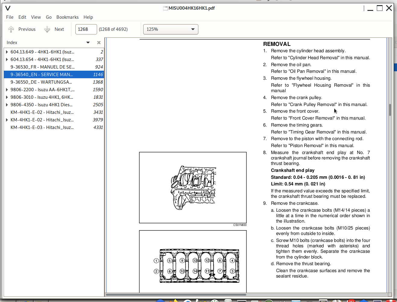
![]()