
John Deere 1023E, 1025R and 1026R Compact Utility Tractor Diagnosis and Repair Service Manual (TM126919)
Complete All Inclusive Technical Manual with electrical wiring diagrams for John Deere 1023E, 1025R and 1026R Compact Utility Tractors, with all the shop information to maintain, diagnose, repair, and rebuild like professional mechanics (Diagnosis, Operation, Tests, Repair, Service, Troubleshooting).
John Deere 1023E, 1025R and 1026R Compact Utility Tractor workshop technical service manual includes:
* Numbered table of contents easy to use so that you can find the information you need fast.
* Detailed sub-steps expand on repair procedure information
* Numbered instructions guide you through every repair procedure step by step.
* Troubleshooting and electrical service procedures are combined with detailed wiring diagrams for ease of use.
* Notes, cautions and warnings throughout each chapter pinpoint critical information.
* Bold figure number help you quickly match illustrations with instructions.
* Detailed illustrations, drawings and photos guide you through every procedure.
* Enlarged inset helps you identify and examine parts in detail.
tm126919 - John Deere 1023E, 1025R and 1026R Compact Utility Tractor Technical Manual.pdf
tm126919 - John Deere 1023E, 1025R and 1026R Compact Utility Tractor Technical Manual.epub
Total Pages: 1,056 pages
File Format: PDF/EPUB/MOBI/AZW (PC/Mac/Android/Kindle/iPhone/iPad; bookmarked, ToC, Searchable, Printable)
Language: English
Table of Contents
Foreword
Section 10: General Information
Group 05: Safety
Recognize Safety Information
Handle Fuel Safely—Avoid Fires
Prevent Battery Explosions
Prepare for Emergencies
Prevent Acid Burns
Service and Operate Chemical Sprayers Safely
Handle Chemical Products Safely
Avoid High-Pressure Fluids
Park Machine Safely
Support Machine Properly
Wear Protective Clothing
Work in Clean Area
Service Machines Safely
Work In Ventilated Area
Illuminate Work Area Safely
Replace Safety Signs
Use Proper Lifting Equipment
Remove Paint Before Welding or Heating
Avoid Heating Near Pressurized Fluid Lines
Keep ROPS Installed Properly
Service Tires Safely
Avoid Harmful Asbestos Dust
Practice Safe Maintenance
Use Proper Tools
Dispose of Waste Properly
Prevent Machine Runaway
Handle Starting Fluid Safely
Service Cooling System Safely
Stay Clear of Rotating Drivelines
Protect Against High Pressure Spray
Construct Dealer-Made Tools Safely
Clean Vehicle of Hazardous Pesticides
Servicing Electronic Control Units
Welding Near Electronic Control Units
Keep Electronic Control Unit Connectors Clean
Live With Safety
Group 10: General Specifications
Machine Specifications 1023E, 1025R, and 1026R EEC
Service Recommendations for O-Ring Boss Fittings
Service Recommendations For Flat Face O-Ring Seal Fittings
Metric Cap Screw Torque Values—Grade 7
Metric Bolt and Screw Torque Values
Unified Inch Bolt and Screw Torque Values
Group 15: Fuel and Lubricants
Diesel Fuel
Handling and Storing Diesel Fuel
Do Not Use Galvanized Containers
Lubricity of Diesel Fuel
Testing Diesel Fuel
BioDiesel Fuel
Filling Fuel Tank
Diesel Engine Break-In Oil
Diesel Engine Oil — Non-Emissions Certified and Certified Tier 1 and Stage I
Oil Filters
Diesel Engine Coolant (engine with wet sleeve cylinder liners)
Operating in Warm Temperature Climates
Additional Information About Diesel Engine Coolants and John Deere LIQUID COOLANT CONDITIONER
Testing Diesel Engine Coolant
Transmission and Hydraulic Oil
Use Correct Transmission/Hydraulic Filter Element
MFWD Axle Housing and Wheel Hub Oil
Grease
Grease (Specific Application)
Mixing of Lubricants
Alternative and Synthetic Lubricants
Lubricant Storage
Group 20: Serial Number Locations
Serial Numbers
Product Identification Number Location
Engine Serial Number Location
Section 20: Engine Repair
Group 05: Engine
Specifications
Other Material
Service Equipment and Tools
Essential or Recommended Tools
Remove Engine—1023E (S.N. —512600), 1025R (S.N. —324500), 1026R (S.N. —510500)
Install Engine—1023E (S.N. —512600), 1025R (S.N. —324500), 1026R (S.N. —510500)
Remove Engine—1023E (S.N. 512601— ), 1025R (S.N. 324501— ), 1026R (S.N. 510501— )
Install Engine—1023E (S.N. 512601— ), 1025R (S.N. 324501— ), 1026R (S.N. 510501— )
Remove and Install Valve Cover
Remove and Install Rocker Arm Assembly and Push Rods
Disassemble, Inspect, and Assemble Rocker Arm Assembly and Push Rods
Remove and Install Exhaust Manifold
Remove and Install Cylinder Head
Disassemble and Assemble Cylinder Head
Recondition Cylinder Head
Replace Crankshaft Rear Oil Seal: 3TNM74
Replace Crankshaft Rear Oil Seal: 3TNV76 and 3TNV80
Remove and Install Crankshaft Rear Oil Seal Case: 3TNV76 and 3TNV80
Replace Crankshaft Front Oil Seal
Remove and Install Timing Gear Cover
Remove, Inspect, and Install Idler Gear
Remove, Inspect, and Install Camshaft Followers
Remove and Install Camshaft
Inspect Camshaft, Gear, Bushing and Bores
Remove and Install Oil Pan and Strainer: 3TNM74
Remove and Install Oil Pan and Strainer: 3TNV76 and 3TNV80
Check Connecting Rod Side Play
Check Crankshaft End Play
Check Connecting Rod Bearing Clearance
Check Crankshaft Main Bearing Clearance
Remove Piston and Connecting Rod
Install Piston and Connecting Rod
Disassemble and Inspect Piston and Connecting Rod
Assemble Piston and Connecting Rod
Inspect Cylinder Bore
Rebore Cylinder
Remove Crankshaft and Main Bearings: 3TNM74
Install Crankshaft and Main Bearings: 3TNM74
Remove Crankshaft and Main Bearings: 3TNV76 and 3TNV80
Install Crankshaft and Main Bearings: 3TNV76 and 3TNV80
Remove and Install Flywheel
Remove and Install Engine Back Plate
Inspect Oil Pump: 3TNM74
Inspect Oil Pump: 3TNV76 and 3TNV80
Group 10: Cooling System
Specifications
Remove and Install Fan and Alternator Belt
Remove and Install Radiator—1023E (S.N. —512600), 1025R (S.N. —324500), 1026R (S.N. —510500)
Remove and Install Radiator—1023E (S.N. 512601— ), 1025R (S.N. 324501— ), 1026R (S.N. 510501— )
Remove and Install Water Pump—1023E (S.N. —512600), 1025R (S.N. —324500), 1026R (S.N. —510500)
Remove and Install Water Pump—1023E (S.N. 512601— ), 1025R (S.N. 324501— ), 1026R (S.N. 510501— )
Remove and Install Thermostat
Remove and Install Coolant Temperature Sensor
Install Block Heater: 3TNM74
Install Block Heater: 3TNV76 and 3TNV80
Section 30: Fuel and Air Repair
Group 05: Fuel System
Specifications
Other Material
Service Equipment and Tools
Bleed Fuel System
Remove and Install Fuel Transfer Pump
Remove and Install Fuel Injection Nozzle
Clean and Inspect Fuel Injection Nozzle
Remove Fuel Injection Pump: 3TNM74
Install Fuel Injection Pump: 3TNM74
Remove Fuel Injection Pump: 3TNV76 and 3TNV80
Install Fuel Injection Pump: 3TNV76 and 3TNV80
Remove and Install Fuel Shutoff Solenoid
Remove and Install Fuel Filter Assembly
Disassemble and Assemble Fuel Filter and Water Separator
Remove and Install Inline Fuel Filter
Group 10: Air Intake and Exhaust Systems
Remove and Install Muffler—1023E (S.N. —512600), 1025R (S.N. —324500), 1026R (S.N. —510500)
Remove and Install Muffler—1023E (S.N. 512601— ), 1025R (S.N. 324501— ), 1026R (S.N. 510501— )
Group 15: Speed Control Linkage
Replace Throttle Cable—1023E (S.N. —512600), 1025R (S.N. —324500), 1026R (S.N. —510500)
Replace Throttle Cable—1023E (S.N. 512601— ), 1025R (S.N. 324501— ), 1026R (S.N. 510501— )
Section 40: Electrical Repair
Group 05: Battery, Starter and Alternator
Specifications
Essential or Recommended Tools
Remove and Install Battery
Remove and Install Starting Motor
Remove and Install Alternator
Disassemble and Inspect Alternator
Assemble Alternator
Group 15: Wiring Harness
Main Wiring Harness—1023E (S.N. —512600)
Main Wiring Harness—1025R (S.N. —324500)
Main Wiring Harness—1026R (S.N. —510500)
Main Wiring Harness—1023E (S.N. 512601— ) and 1025R (S.N. 324501— )
Main Wiring Harness—1026R (S.N. 510501— )
Fender Wiring Harness
Section 50: Power Train Repair
Group 15: Transmission
Specifications
Other Material
Remove Transmission—1023E (S.N. —512600), 1025R (S.N. —324500), 1026R (S.N. —510500)
Install Transmission—1023E (S.N. —512600), 1025R (S.N. —324500), 1026R (S.N. —510500)
Remove Transmission—1023E (S.N. 512601— ), 1025R (S.N. 324501— ), 1026R (S.N. 510501— )
Install Transmission—1023E (S.N. 512601— ), 1025R (S.N. 324501— ), 1026R (S.N. 510501— )
Remove and Install Hydrostatic Drive
Disassemble and Inspect Hydrostatic Drive
Assemble Hydrostatic Drive
Remove and Install Range Transmission
Group 20: Rear PTO Driveshaft
Specifications
Other Material
Essential or Recommended Tools
Remove PTO Clutch
Disassemble and Inspect PTO Clutch
Assemble PTO Clutch
Install PTO Clutch
Remove and Inspect Rear PTO Driveshaft and Gears
Install Rear PTO Driveshaft and Gears
Remove and Inspect Mid PTO Driveshaft and Gears
Install Mid PTO Driveshaft and Gears
Group 25: Differential
Specifications
Other Material
Remove and Install Differential
Disassemble and Inspect Differential
Assemble Differential
Group 30: Final Drives
Essential or Recommended Tools
Remove and Install Rear Axle
Group 35: Mechanical Front Wheel Drive
Specifications
Remove Front Axle
Install Front Axle
Disassemble Front Axle
Assemble Front Axle
Disassemble Front Outer Axle
Assemble Front Outer Axle
Disassemble MFWD Differential
Assemble MFWD Differential
Section 60: Steering and Brake Repair
Group 05: Steering Repair
Specifications
Remove and Install Steering Wheel
Remove and Install Steering Cylinder
Remove and Install Tilt Steering Assembly—1023E (S.N. —512600), 1025R (S.N. —324500), 1026R (S.N. —510500)
Remove and Install Tilt Steering Assembly—1023E (S.N. 512601— ), 1025R (S.N. 324501— ), 1026R (S.N. 510501— )
Disassemble Tilt Steering Assembly—1023E (S.N. —512600), 1025R (S.N. —324500), 1026R (S.N. —510500)
Assemble Tilt Steering Assembly—1023E (S.N. —512600), 1025R (S.N. —324500), 1026R (S.N. —510500)
Disassemble Tilt Steering Assembly—1023E (S.N. 512601— ), 1025R (S.N. 324501— ), 1026R (S.N. 510501— )
Assemble Tilt Steering Assembly—1023E (S.N. 512601— ), 1025R (S.N. 324501— ), 1026R (S.N. 510501— )
Remove Steering Control Unit (SCU)—1023E (S.N. —512600), 1025R (S.N. —324500), 1026R (S.N. —510500)
Install Steering Control Unit (SCU)—1023E (S.N. —512600), 1025R (S.N. —324500), 1026R (S.N. —510500)
Remove Steering Control Unit (SCU)—1023E (S.N. 512601— ), 1025R (S.N. 324501— ), 1026R (S.N. 510501— )
Install Steering Control Unit (SCU)—1023E (S.N. 512601— ), 1025R (S.N. 324501— ), 1026R (S.N. 510501— )
Remove and Install Tie Rod
Group 10: Brake Repair
Specifications
Other Material
Disassemble and Inspect Brakes
Assemble Brakes
Section 70: Hydraulics Repair
Group 05: Hydraulic Pump and Filter
Specifications
Remove and Install Hydraulic Pump
Disassemble and Inspect Hydraulic Pump
Assemble Hydraulic Pump
Remove and Install Oil Suction Screen
Remove PTO Valve
Install PTO Valve
Group 10: Rockshaft
Specifications
Other Material
Remove Rockshaft Housing
Install Rockshaft Housing
Disassemble Rockshaft
Assemble Rockshaft
1025R Disassemble Rockshaft Position Feedback
1025R Assemble Rockshaft Position Feedback
Group 15: Selective Control Valve
Specifications
Remove and Install Selective Control Valve (SCV)
Inspect Selective Control Valve (SCV)
Section 80: Miscellaneous Repair
Group 10: Wheels
Specifications
Remove and Install Front Wheels
Remove and Install Rear Wheels
Group 15: 3-Point Hitch
Adjust 3-Point Hitch
Remove and Install 3-Point Hitch
Group 20: Hood
Remove and Install Hood—1023E (S.N. —512600), 1025R (S.N. —324500), 1026R (S.N. —510500)
Remove and Install Hood—1023E (S.N. 512601— ), 1025R (S.N. 324501— ), 1026R (S.N. 510501— )
Group 25: Mid-Mount Lift
Specifications
Remove Mid Mount Mower Draft Arm
Install Mid Mount Mower Draft Arm
Remove Mid Mount Rockshaft and Lift Arm
Install Mid Mount Rockshaft and Lift Arm
Install Mid Mount Lift Actuator, Mechanical
Install Mid Mount Lift Actuator, Hydraulic
Remove Mid Mount Mower Lift Hydraulic Hose and Cylinder
Install Mid Mount Mower Lift Hydraulic Cylinder and Hose
Adjust Mid Mount Lift - Mechanical Lift
Section 90: Operator's Station Repair
Group 05: Seat and Support
Specifications
Remove Seat
Install Seat
Remove Seat Base
Install Seat Base
Group 10: ROLL-GARD
Specifications
Remove ROPS
Install ROPS
Group 15: Operator Platform
Specifications
Remove Control Panel—1023E (S.N. —512600), 1025R (S.N. —324500), 1026R (S.N. —510500)
Install Control Panel—1023E (S.N. —512600), 1025R (S.N. —324500), 1026R (S.N. —510500)
Remove Control Panel—1023E (S.N. 512601— ), 1025R (S.N. 324501— ), 1026R (S.N. 510501— )
Install Control Panel—1023E (S.N. 512601— ), 1025R (S.N. 324501— ), 1026R (S.N. 510501— )
Remove and Install Center Closeout Panel
Remove and Install Foot Deck—1023E (S.N. 512601— ), 1025R (S.N. 324501— ), 1026R (S.N. 510501— )
Group 20: Fenders
Remove Right Fender
Install Right Fender
Remove Left Fender and Fuel Tank
Install Left Fender and Fuel Tank
Section 210: Operational Checkout Procedures
Group 05: Operational Checkout Procedures
Summary of References
System Checks
Rear Differential Lock Operational Check
PTO Operational Checks
RIO Operational Check
PTO and Seat Switch Interface Check
Brakes Operational Check
Steering Preliminary Check
Steering Operational Check
Hydraulic System Operational Checks
Section 220: Engine Operation, Tests, and Adjustments
Group 05: Component Location
Summary of References
3TNM74 Engine Component Locations
3TNV76 and 3TNV80 Engine Component Locations
Group 10: Theory of Operation
Summary of References
Cooling System Theory of Operation
Lubrication System Theory of Operation
Group 15: Diagnosis, Tests, and Adjustments
Summary of References
Specifications
Other Material
Service Equipment and Tools
Essential or Recommended Tools
Adjust Throttle Cable
Adjust Slow Idle
Adjust Fast Idle
Adjust Valve Clearance
Check Camshaft End Play
Check Timing Gear Backlash
Cylinder Compression Test—3TNM74
Cylinder Compression Test—3TNV76 and 3TNV80
Pressure Test Cooling System
Test Thermostat
Pressure Test Radiator Cap
Test Oil Pressure
Adjust Fan and Alternator Belt
Section 230: Fuel and Air Operation, Tests, and Adjustments
Group 05: Component Location
Summary of References
Fuel System
Group 10: Theory of Operation
Summary of References
Air Intake System Theory of Operation
Fuel System Theory of Operation
Group 15: Diagnosis, Test and Adjustments
Summary of References
Specifications
Other Material
Service Equipment and Tools
Essential or Recommended Tools
Test Fuel Injection System
Test Fuel Injection Nozzle
Injection Pump Timing (EPA Engines)
Check Injection Pump Static Timing
Adjust Fuel Injection Timing: 3TNM74
Adjust Fuel Injection Timing: 3TNV76 and 3TNV80
Test Fuel Supply Pressure and Flow
Test Air Filter Restriction Indicator
Section 240: Electrical System Operation, Tests, and Adjustments
Group 05: Theory of Operation
Summary of References
Charging Circuit Theory of Operation
Cranking and Starting Circuit Theory of Operation
Instrument Control Cluster (ICC) Theory of Operation
Power Circuit Theory of Operation
PTO Circuit Theory of Operation
Lighting Circuit Theory of Operation
Group 10: Wiring Schematics
Wiring Schematics - Summary of References
Schematic Information
(SE01) Operator Station, Key Switch, Starting, and Charging
(SE02A) Lighting, Turn Signal, and Work Lights—1023E and 1025R
(SE02B) Lighting, Turn Signal and Horn—1026R
(SE03 - SE06) Instrument Control Cluster, Seat, Brake, Park Brake, Neutral Switches PTO, Power Port, and Mower
Group 15: Diagnosis, Test and Adjustments
Summary of References
Specifications
Service Equipment and Tools
Essential or Recommended Tools
Power Circuit Diagnosis
Charge Circuit Diagnosis
Crank Circuit Diagnosis
Fuel Shutoff Circuit Diagnosis
Glow Plug Circuit Diagnosis
PTO Circuit Diagnosis
Lighting Circuit Diagnosis—1023E
Lighting Circuit Diagnosis—1025R
Instrument Control Cluster (ICC) Diagnosis
Key Switch Test
PTO Switch Test
Park Brake Switch Test
Reverse Pedal Switch Test
Reverse Pedal Switch Adjustment
Seat Switch Test
Light Switch Test
Turn Signal Switch Test
Hazard Switch Test
PTO MBR Switch Test
PTO Solenoid Test
Neutral Switch Test
Horn Switch Test
Relay Test
Oil Pressure Switch Test
Coolant Temperature Sensor Test
Fuel Shutoff Solenoid Test
Regulated Voltage Output Test
Group 20: Connector Information
Summary of References
E01 and E02 Headlight Connector
G02 Alternator Connector
J1 Display Connector—ICC
J2 Display Connector—ICC
J3 Display Connector—ICC
K01—K04 Relay Connector
K05—K06 Relay Connector
M01 Start Motor Connector
M02 Fuel Pump Connector
R01 Glow Plug Connector
S01 Key Switch Connector
S02 Light Switch Connector
S03 Turn Signal Switch Connector
S04 Neutral Start Switch Connector
S05 PTO Switch Connector
S08 MBR Switch Connector
S10 Mow Lift Switch Connector
S13 Hazard Switch Connector
S38 Seat Switch Connector
S40 Front Hitch Detection Connector
S41 Park Brake Switch Connector
S42 Brake Switch Connector
S60 Reverse Pedal Sense Connector
X03 Power Port Connector
X09 Mow Lift Solenoid Connector
X54 RH Fender Light Connector
X55 LH Fender Light Connector
Y02 Fuel Shutoff Solenoid Connector
Y03 PTO Solenoid Connector
Group 25: Component Location
Summary of References
Electrical Components
Load Center
Section 250: Power Train Operation, Tests, and Adjustments
Group 05: Component Location
Summary of References
Transmission Sub-Assemblies
Driveshaft
Hydraulic Transmission
Gear Transmission Sub-Assemblies
Transmission Housing
Range Gears, Pinion, and Bevel Gear
Differential
Brakes
Axles
Mechanical Front Wheel Drive (MFWD)
PTO Clutch
PTO Drive
Rockshaft - 1023E
Rockshaft With Feedback - 1025R
Hydraulic Pump and PTO Valve
Front Axle Input Gear and Differential
Front Axle Case and Tie Rod
Front Axle Final Drive Gears
Group 10: Theory of Operation
Summary of References
Gear Train Operation
Range Gear Operation
MFWD Operation
PTO Operation
Group 15: Diagnosis, Test and Adjustments
Summary of References
Specifications
Essential or Recommended Tools
MFWD Diagnosis
Adjust Neutral Creep
Adjust Differential Lock
Adjust Forward and Reverse Pedals
Cone Point and Backlash Setting
Section 260: Steering and Brake Operation, Tests, and Adjustments
Group 05: Component Location
Summary of References
Steering Components
Tilt Steering Components—1023E (S.N. —512600), 1025R (S.N. —324500), 1026R (S.N. —510500)
Tilt Steering Components—1023E (S.N. 512601— ), 1025R (S.N. 324501— ), 1026R (S.N. 510501— )
Brake Components
Park Brake Components - Export
Group 10: Theory of Operation
Summary of References
Steering System Operation
Group 15: Diagnosis, Test and Adjustments
Summary of References
Specifications
Adjust Brakes
Adjust Park Brake Engagement
Adjust Park Brake Engagement EEC
Check Toe-in
Steering Pressure Check
Steering System Test
Section 270: Hydraulic System Operation, Tests, and Adjustments
Group 05: Component Location
Summary of References
Hydraulic Pump—1023E (S.N. —512600), 1025R (S.N. —324500), 1026R (S.N. —510500)
Hydraulic Pump—1023E (S.N. 512601— ), 1025R (S.N. 324501— ), 1026R (S.N. 510501— )
PTO Solenoid
Group 10: Theory of Operation
Summary of References
Surge Relief Valve Operation
Group 15: Diagnosis
Summary of References
Diagnostic Information
Preliminary Hydraulic System Inspection
Entire Hydraulic System Fails to Function/No Hydraulic Pump Output
Insufficient Pump Delivery
Hydraulic Functions Too Slow
Excessive Pump Pressure
Slow Hydraulic Pump Response
Excessive Pump Noise During Operation
Rockshaft Does Not Lift or Lifts Slowly
Rockshaft Does Not Lower or Lowers Slowly
Neutral Position Unstable, Rockshaft Drops after Engine Shut Down
Mid-Mount Joystick Does Not Return to Neutral Position—Mid-Mount SCV
Mid-Mount Joystick Does Not Remain in Detent Position—Mid-Mount SCV
Remote Cylinder Does Not Extend or Retract
Remote Cylinder Settles Under Load
Remote Cylinder Operates Too Fast or Too Slow
Group 20: Hydraulic Tests
Summary of References
Specifications
Essential or Recommended Tools
Hydraulic Oil Warm-up Procedure
Test SCV Implement Relief Pressure
Test PTO Cluch Pressure
Test HST Charge Pressure
Check Rate of Drop/Stop Valve
Pump Flow Test (Tractors With SCV)
Main Relief Valve Test (Tractors With SCV)
SCV Leakage Test
Rockshaft Lift Cycle Test
Rockshaft Leakdown Test
Group 25: Adjustments
Summary of References
Specifications
Adjust Rockshaft Position Feedback
Adjust Rockshaft Feedback Friction Washers
Group 30: Hydraulic Schematics
Summary of References
Hydraulic Circuit Symbols
1023E Hydraulic Schematic
1025R Hydraulic Schematic
Section 299: Service Tools
Group 05: Dealer Fabricated Tools
Summary of References
PTO Clutch Spring Compression Tool
Group 10: Service Tools and Kits
Essential or Recommended Tools
John Deere 1023E, 1025R and 1026R Compact Utility Tractor Diagnosis and Repair Service Manual (TM126919)
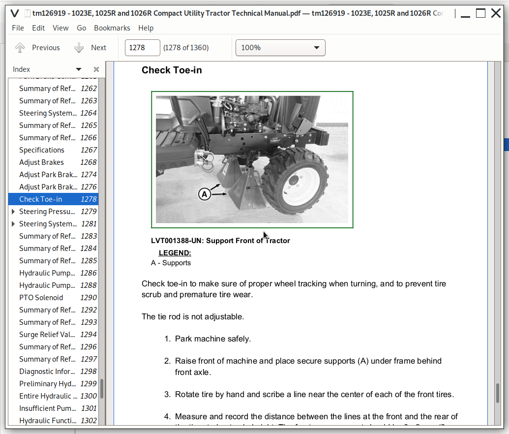
![]()