
Hitachi ZX470-6, ZX470LC-6, ZX490H-6, ZX490LCH-6, ZX490R-6, ZX490LCR-6, ZX530LCH-6 Excavators Repair Service Manuals
Complete service repair manual with electrical wiring diagrams for Hitachi ZX470-6, ZX470LC-6, ZX490H-6, ZX490LCH-6, ZX490R-6, ZX490LCR-6, ZX530LCH-6 Excavators, with all the shop information to maintain, diagnose, repair, and service like professional mechanics.
Hitachi ZX470-6, ZX470LC-6, ZX490H-6, ZX490LCH-6, ZX490R-6, ZX490LCR-6, ZX530LCH-6 Excavators workshop service repair manual includes:
* Numbered table of contents easy to use so that you can find the information you need fast.
* Detailed sub-steps expand on repair procedure information
* Numbered instructions guide you through every repair procedure step by step.
* Troubleshooting and electrical service procedures are combined with detailed wiring diagrams for ease of use.
* Notes, cautions and warnings throughout each chapter pinpoint critical information.
* Bold figure number help you quickly match illustrations with instructions.
* Detailed illustrations, drawings and photos guide you through every procedure.
* Enlarged inset helps you identify and examine parts in detail.
Total Pages: 1,729 pages
File Format: PDF (bookmarked, ToC, Searchable, Printable, high quality)
Language: English
MANUAL LIST:
TOJAG50-EN-00 - Hitachi ZX470-6, ZX470LC-6, ZX490H-6, ZX490LCH-6, ZX490R-6, ZX490LCR-6, ZX530LCH-6 Hydraulic Excavator Technical Manual (Operational Principle).pdf
TTJAG50-EN-00 (attach to) - Hitachi ZX470-6, ZX470LC-6, ZX490H-6, ZX490LCH-6, ZX490R-6, ZX490LCR-6, ZX530LCH-6 Hydraulic Excavator Electrical Circuit Diagram.pdf
TTJAG50-EN-00 - Hitachi ZX470-6, ZX470LC-6, ZX490H-6, ZX490LCH-6, ZX490R-6, ZX490LCR-6, ZX530LCH-6 Hydraulic Excavator Technical Manual (Troubleshooting).pdf
WAG50-EN-00 - Hitachi ZX470-6, ZX470LC-6, ZX490H-6, ZX490LCH-6, ZX490R-6, ZX490LCR-6, ZX530LCH-6 Hydraulic Excavator Workshop Manual.pdf
MAIN SECTIONS
TOJAG50-EN-00 - Hitachi ZX470-6, ZX470LC-6, ZX490H-6, ZX490LCH-6, ZX490R-6, ZX490LCR-6, ZX530LCH-6 Hydraulic Excavator Technical Manual (Operational Principle).....1
TOJAG50-EN-00.....1
CONTENTS.....3
INTRODUCTION.....9
SYMBOL AND ABBREVIATION.....11
SECTION AND GROUP CONTENTS.....13
SECTION 1GENERAL.....15
Group 1 Specifications.....17
Specifications ZX470-6, 470LC-6.....17
Working Ranges ZX470-6, 470LC-6.....18
Specifications ZX490H-6, 490LCH-6.....19
Working Ranges ZX490H-6, 490LCH-6.....20
Specifications ZX530LCH-6.....21
Working Ranges ZX530LCH-6.....22
Group 2 Component Layout.....23
Main Component.....23
Electrical System (Overview).....25
Electrical System (Rear Tray).....26
Electrical System (Switch Panel).....27
Electrical System (Cab Behind Side).....28
Engine 1.....30
Engine 2.....31
Aftertreatment Device.....32
Pump Device.....33
Control Valve.....34
DEF Tank.....35
Expansion Tank.....35
Check Valve.....36
Signal Control Valve.....36
4-Spool Solenoid Valve Unit.....39
2-Spool Solenoid Valve Unit.....39
Fan Valve.....39
Layout of Attachment Spec. Parts (Hydraulic System).....40
Group 3 Component Specifications.....45
Engine.....45
Engine Accessories.....49
Hydraulic Component.....51
Electrical Component.....55
SECTION 2SYSTEM.....59
Group 1 Controller.....61
Outline.....61
CAN Circuit.....62
Group 2 Control System.....65
Outline.....65
Engine Control.....68
Pump Control.....98
Valve Control (Standard).....126
Other Control.....158
Group 3 Engine System.....171
Outline.....171
ECM System.....172
Fuel Injection Control.....174
Fuel Injection Amount Correction Control.....182
EGR Control.....184
Preheating Control.....186
Variable Turbocharger Control.....187
Alarm Control.....188
Urea SCR System.....189
Engine Output Restriction Control (INDUCEMENT).....200
Aftertreatment Device.....204
Aftertreatment Device Regeneration Control.....206
Group 4 Hydraulic System.....209
Outline.....209
Pilot Circuit.....210
Main Circuit.....226
Breaker/Pulverizer/Crusher Circuit (Optional).....252
Group 5 Electrical System.....261
Outline.....261
Main Circuit.....262
Electric Power Circuit (Key Switch: OFF).....264
CAN Circuit.....266
Accessory Circuit (Key Switch: ACC).....268
Starting Circuit (Key Switch: START).....270
Charging Circuit (Key Switch: ON).....272
Surge Voltage Prevention Circuit.....276
Pilot Shut-Off Circuit (Key Switch: ON).....278
Auto Shut-Down Circuit/Automatic Engine Stop Circuit at Low Temperature.....280
Engine Stop Circuit.....282
Monitor Circuit.....285
Security Circuit.....286
Radio Circuit.....288
Air Conditioner Circuit.....288
Accessory Circuit.....291
Work Light Circuit.....292
Wiper/Washer Circuit.....294
Cab Light Circuit.....296
SECTION 3COMPONENT OPERATION.....301
Group 1 Pump Device.....303
Outline.....303
Main Pump.....304
Regulator.....306
Pump Control Solenoid Valve.....314
Fan Pump.....316
Fan Pump Flow Rate Control.....318
Pilot Pump.....320
Pump Delivery Pressure Sensor.....320
Pump Control Pressure Sensor.....320
Group 2 Swing Device.....321
Outline.....321
Swing Reduction Gear.....322
Swing Motor.....323
Swing Parking Brake.....324
Valve Unit.....326
Group 3 Control Valve.....329
Outline.....329
Hydraulic Circuit.....346
Flow Combiner Valve.....352
Main Relief valve.....354
Overload Relief Valve (with Make-Up Function).....358
Boom Overload Relief Valve (Low Pressure).....364
Regenerative Valve.....366
Anti-Drift Valve.....370
Flow Rate Control Valve.....374
Boom Lower Meter-In Cut Valve.....382
Bypass Shut-Out Valve.....384
Auxiliary Flow Combiner Valve.....388
Group 4 Pilot Valve.....391
Outline.....391
Operation (Front Attachment/Swing and Travel Pilot Valves).....393
Operation (Auxiliary, Counterweight Removal/Installation Pilot Valves).....401
Shockless Function (Only for Travel Pilot Valve).....406
Group 5 Travel Device.....407
Outline.....407
Travel Reduction Gear.....408
Travel Motor.....410
Parking Brake.....412
Travel Brake Valve.....414
Overload Relief Valve.....418
Travel Mode Control.....420
Group 6 Signal Control Valve.....425
Outline.....425
Pilot Port.....426
Shuttle Valve.....430
Shockless Valve.....434
Pump 1 and Pump 2 Flow Rate Control Valves.....438
Arm Flow Rate Control Valve Control Spool, Flow Combiner Valve Control Spool, Swing Parking Brake Release Spool.....440
Group 7 Others (Upperstructure).....441
Pilot Shut-Off Solenoid Valve.....441
Solenoid Valve.....443
Hose Rupture Valve (Optional).....446
Fan Motor.....450
Fan Valve.....451
Pilot Relief Valve.....457
Shockless Valve.....458
Accumulator (Pilot Circuit).....460
Accumulator (Attachment Circuit) (Optional).....461
Selector Valve (Optional).....462
Distribution Valve.....464
Group 8 Others (Undercarriage).....467
Swing Bearing.....467
Centerjoint.....468
Track Adjuster.....469
SERVICE MANUAL REVISION REQUEST FORM.....473
TTJAG50-EN-00 (attach to) - Hitachi ZX470-6, ZX470LC-6, ZX490H-6, ZX490LCH-6, ZX490R-6, ZX490LCR-6, ZX530LCH-6 Hydraulic Excavator Electrical Circuit Diagram.....475
ELECTRICAL CIRCUIT DIAGRAM.....475
AIR CONDITIONER CIRCUIT DIAGRAM.....476
CONNECTORS.....477
CAB HARNESS.....478
MAIN HARNESS.....479
ENGINE HARNESS.....480
PUMP HARNESS.....481
CONTROL VALVE HARNESS.....482
NOx HARNESS.....483
EXPANSION TANK SUB HARNESS.....484
DEF SENSOR UNIT HARNESS.....485
MONITOR HARNESS.....486
KEY SWITCH HARNESS.....487
MANUAL REGENERATION SWITCH HARNESS.....488
OIL COOLER FAN REVERSE ROTATION SWITCH HARNESS.....489
ENGINE STOP SWITCH HARNESS.....490
FLOOR EARTH HARNESS.....491
PILOT SHUT-OFF SOLENOID VALVE HARNESS.....492
STARTER HARNESS.....493
GSM (MOBILE COMMUNICATION TERMINAL) HARNESS.....494
SATELLITE COMMUNICATION HARNESS.....495
AUTO LUBRICATION HARNESS.....496
AUTO LUBRICATION ON/OFF SWITCH HARNESS.....497
REARVIEW CAMERA HARNESS.....498
COUNTERWEIGHT REMOVAL SWITCH HARNESS (OPTION).....499
BOOM MODE SWITCH AND SEAT HEATER SWITCH HARNESS (OPTION).....500
BREAKER HARNESS (OPTION).....501
WORK LIGHT (ON THE CAB ROOF) HARNESS 1 (OPTION).....502
WORK LIGHT (ON THE CAB ROOF) HARNESS 2 (OPTION).....503
ADDITIONAL WORK LIGHT (ON THE CAB ROOF) HARNESS (OPTION).....504
HYDRAULIC CIRCUIT DIAGRAM (STANDARD).....505
HYDRAULIC CIRCUIT DIAGRAM (OPTIONAL).....506
HYDRAULIC CIRCUIT DIAGRAM (WITH HOSE RUPTURE VALVE)(OPTIONAL.....507
HYDRAULIC CIRCUIT DIAGRAM (WITH COUNTERWEIGHT REMOVAL AND INSTALLATION DEVICE)(OPTIONAL).....508
TTJAG50-EN-00 - Hitachi ZX470-6, ZX470LC-6, ZX490H-6, ZX490LCH-6, ZX490R-6, ZX490LCR-6, ZX530LCH-6 Hydraulic Excavator Technical Manual (Troubleshooting).....509
TTJAG50-EN-00.....509
CONTENTS.....511
INTRODUCTION.....515
SYMBOL AND ABBREVIATION.....517
SAFETY.....519
SECTION AND GROUP CONTENTS.....561
SECTION 4 OPERATIONAL PERFORMANCE TEST.....563
Group 1 Introduction.....565
Operational Performance Tests.....565
Preparation for Performance Tests.....566
Group 2 Standard.....567
Operational Performance Standard Table.....567
Main Pump P-Q Diagram.....571
Fan Pump P-Q Diagram.....572
Sensor Activating Range.....573
MPDR. Monitor Indicating Values (MC).....574
MPDr. Monitor Indicating Values (ECM).....580
Group 3 Engine Test.....581
Engine Speed.....581
Lubricant Consumption.....584
Group 4 Machine Performance Test.....585
Travel Speed.....585
Track Revolution Speed.....586
Mistrack Check.....587
Travel Parking Leakage.....588
Swing Speed.....589
Swing Function Drift Check.....590
Swing Motor Leakage.....592
Maximum Swingable Slant Angle.....594
Swing Bearing Play.....596
Hydraulic Cylinder Cycle Time.....598
Dig Function Drift Check.....600
Control Lever Operating Force.....603
Control Lever Stroke.....604
Combined Operation of Boom Raise and Swing Function Check.....605
Group 5 Component Test.....607
Primary Pilot Pressure.....607
Secondary Pilot Pressure.....609
4-Spool Solenoid Valve Set Pressure.....610
2-Spool Solenoid Valve Set Pressure.....611
Main Pump Delivery Pressure.....613
Fan Pump Delivery Pressure.....614
Main Relief Valve Set Pressure.....615
Overload Relief Valve Set Pressure.....621
Main Pump Flow Rate Measurement.....624
Fan Pump Flow Rate Measurement.....630
Swing Motor Drainage.....636
Travel Motor Drainage.....638
Group 6 Adjustment.....641
Pump Learning.....641
Torque Adjustment.....642
Connection.....643
Rewrite of Aftertreatment Device Serial No.....645
How to Clear Fault Code.....646
Procedure after Replacing DCU and ECM.....647
Air Bleeding from the Diesel Exhaust Fluid Defrosting Piping.....648
How to Check Manual Regeneration Switch.....649
Remedy at DEF Pressure Decrease.....650
Remedy at DEF Abnormal Quality.....652
Clean DEF Tank.....654
Remedy When Mixing Oil DEF Tank.....655
SECTION 5 TROUBLESHOOTING.....659
Group 1 Diagnosing Procedure.....661
Introduction.....661
Diagnosis Procedure.....662
Electrical System Inspection.....665
Precautions for Inspection and Maintenance.....666
Instructions for Disconnecting Connectors.....668
Fuse Inspection.....670
Fusible Link Inspection.....673
Battery Voltage Check.....674
Alternator Check.....675
Continuity Check.....676
Voltage and Current Measurement.....678
Check by False Signal.....685
Test Wire Harness.....686
Group 2 Monitor.....689
Outline.....689
Operating Procedures of Service Menu.....690
Setting Menu.....659
Inspection of Engine Oil Level, Coolant Level,Hour Meter, and Fuel Gauge.....728
Fuel Gauge, Coolant Temperature Gauge,DEF/AdBlue Gauge.....729
Group 3 e-Service.....731
Outline.....731
List of Operation Data.....732
Communication System.....734
Group 4 Component Layout.....735
Main Component.....735
Electrical System (Overview).....737
Electrical System (Rear Tray).....738
Electrical System (Switch Panel).....739
Electrical System (Cab Behind Side).....740
Engine 1.....742
Engine 2.....743
Aftertreatment Device.....744
Pump Device.....745
Control Valve.....746
DEF Tank.....747
Expansion Tank.....747
Check Valve.....748
Signal Control Valve.....748
Swing Device.....750
Travel Device.....750
4-Spool Solenoid Valve Unit.....751
Fan Valve.....751
2-Spool Solenoid Valve Unit.....751
Layout of Attachment Spec. Parts(Hydraulic System).....752
Layout of Control Valve.....756
Pilot Port (Signal Control Valve).....772
Layout of Connector.....776
Port Layout of Control Valve (Main Circuit).....786
Port Layout of Control Valve (Pilot Circuit).....788
Group 5 Troubleshooting A.....791
Troubleshooting A (Base Machine DiagnosisBy Using Fault Codes) Procedure.....791
MC Fault Code List.....793
ECM Fault Code List.....815
DCU Fault Code List.....829
Monitor Controller (Monitor) Fault Code List.....836
Air Conditioner Controller Fault Code List.....840
Communication Terminal Fault Code List.....841
MC Fault Codes 11000 to 11002.....843
MC Fault Code 11003.....844
MC Fault Codes 11004, 11006, 11007,11009Monitor Controller (Monitor)Fault Codes 13002, 13003, 13005.....846
CAN0 Harness Check.....847
ISO-CAN (Engine) Harness Check.....850
MC Fault Codes 11005, 11008, 11010Monitor Controller (Monitor)Fault Codes 13004, 13006, 13007.....853
CAN1 Harness Check.....854
MC Fault Code 11100.....857
MC Fault Code 11101.....858
MC Fault Codes 11200, 11202.....859
MC Fault Codes 11992, 11994.....860
MC Fault Codes 11301 to 11303.....861
MC Fault Codes 11304, 11325.....862
MC Fault Codes 11995, 11997, 11998.....863
MC Fault Codes 11942 to 11944.....864
MC Fault Codes 11945, 11978, 11979.....865
MC Fault Code 11990.....866
MC Fault Code 11405.....867
MC Fault Code 11408.....868
MC Fault Code 11412.....869
MC Fault Code 11428.....870
MC Fault Code 11948.....871
MC Fault Code 11950.....872
MC Fault Code 11951.....873
MC Fault Code 11952.....874
MC Fault Code 11953.....875
MC Fault Code 11981.....876
MC Fault Code 11982.....877
MC Fault Code 11989.....878
MC Fault Code 11802.....879
MC Fault Code 11901.....880
MC Fault Codes 11910, 11911, 11914,11918, 11920.....881
MC Fault Code 11946.....882
MC Fault Code 11947.....883
MC Fault Codes 11971, 11972.....884
MC Fault Codes 11974, 11975.....885
MC Fault Codes 11983, 11984.....886
MC Fault Codes 11985, 11986.....887
MC Fault Codes 20000, 20003, 20005, 20006,20008.....888
MC Fault Codes 20009, 20010, 20062.....889
Monitor Controller (Information)Fault Codes 13304, 13310.....890
Monitor Controller (Information)Fault Code 13311.....891
Monitor Controller (Information)Fault Codes 20100 to 20107, 20114.....892
Monitor Controller (Information)Fault Codes 20109, 20110, 20113, 20133, 20141,20142, 20145, 20146, 20149.....893
Air Conditioner Controller Fault Codes11 to 22.....894
Air Conditioner Controller Fault Codes43 to 92.....895
Group 6 Troubleshooting B.....897
Troubleshooting B (Machine Diagnosis byUsing Trouble Symptom) Procedure.....897
Relationship between Machine TroubleSymptoms and Related Parts.....899
Correlation between Trouble Symptoms andPart Failures.....927
Engine System Troubleshooting.....945
All Actuator System Troubleshooting.....952
Front Attachment System Troubleshooting.....959
Swing System Troubleshooting.....972
Travel System Troubleshooting.....975
Other System Troubleshooting.....979
Exchange Inspection.....986
Emergency Boom Lowering Procedure.....989
Group 7 Air Conditioner.....991
Outline.....991
Functions of Main Parts.....994
Troubleshooting.....999
Air Conditioner Controller Fault Code List.....1000
Air Conditioner Controller Fault Codes 11 to 22.....1001
Air Conditioner Controller Fault Codes 43 to 92.....1002
Work after Replacing Components.....1024
Refill Compressor Oil.....1025
Charge Air Conditioner with Refrigerant.....1026
Hose and Pipe Tightening Torque.....1034
SERVICE MANUAL REVISION REQUEST FORM.....1037
The Attached Diagram List.....1038
WAG50-EN-00 - Hitachi ZX470-6, ZX470LC-6, ZX490H-6, ZX490LCH-6, ZX490R-6, ZX490LCR-6, ZX530LCH-6 Hydraulic Excavator Workshop Manual.....1039
WJAG50-EN-00.....1039
CONTENTS.....1041
SECTION 1 GENERAL.....1041
SECTION 2 .....1043
SECTION 3 .....1045
SECTION 4 .....1047
SECTION 5 .....1049
INTRODUCTION.....1051
To The Reader.....1051
Additional References.....1051
Manual Composition.....1051
Page Number.....1051
Trademark.....1051
Safety Alert Symbol and Headline Notations.....1052
Units Used.....1052
SYMBOL AND ABBREVIATION.....1053
SAFETY.....1055
Recognize Safety Information.....1055
Understand Signal Words.....1055
Follow Safety Instructions.....1056
Prepare for Emergencies.....1057
Wear Protective Clothing.....1057
Protect Against Noise.....1058
Inspect Machine.....1058
General Precautions for the Cab.....1059
Use Handholds and Steps.....1060
Adjust the Operator's Seat.....1060
Ensure Safety Before Rising from or Leaving Operator’s Seat.....1061
Fasten Your Seat Belt.....1061
Move and Operate Machine Safely.....1062
Operate Only from Operator's Seat.....1062
Jump Starting.....1063
Keep Riders off Machine.....1063
Precautions for Operations.....1064
Investigate Job Site Beforehand.....1065
Install OPG Guard.....1066
Restriction of Attachment Installation.....1066
Provide Signals for Jobs Involving Multiple Machines.....1067
Confirm Direction of Machine to Be Driven.....1067
Drive Machine Safely.....1068
Avoid Injury from Rollaway Accidents.....1070
Avoid Injury from Back-Over and Swing Accidents.....1071
Keep People Clear from Working Area.....1072
Never Position the Bucket Over Anyone.....1072
Avoid Undercutting.....1073
Avoid Tipping.....1073
Never Undercut a High Bank.....1074
Dig with Caution.....1074
Operate with Caution.....1074
Avoid Power Lines.....1075
Precautions for Lightning.....1075
Object Handling.....1076
Protect Against Flying Debris.....1076
Park Machine Safely.....1077
Handle Fluids Safely−Avoid Fires.....1077
Transport Safely.....1078
Practice Safe Maintenance.....1079
Warn Others of Service Work.....1080
Support Machine Properly.....1080
Stay Clear of Moving Parts.....1081
Prevent Parts from Flying.....1081
Avoid Injury from Attachment Falling Accident.....1082
Prevent Burns.....1082
Replace Rubber Hoses Periodically.....1083
Avoid High-Pressure Fluids.....1083
Prevent Fires.....1084
Evacuating in Case of Fire.....1086
Beware of Exhaust Fumes.....1086
Precautions for Welding and Grinding.....1087
Avoid Heating Near Pressurized Fluid Lines.....1088
Avoid Applying Heat to Lines Containing Flammable Fluids.....1088
Precautions for Handling Accumulator and Gas Damper.....1088
Remove Paint Before Welding or Heating.....1089
Beware of Asbestos and Silica Dust and Other Contamination.....1089
Prevent Battery Explosions.....1090
Service Air Conditioning System Safely.....1090
Handle Chemical Products Safely.....1091
Dispose of Waste Properly.....1091
Never Ride Attachment.....1092
Notes on Aftertreatment Device.....1092
Precautions for Communication Terminal.....1092
Precautions for Communication Terminal Equipment.....1093
Notes on Protection of Operator’s Station when the Machine Rolls Over.....1095
Before Returning the Machine to the Customer.....1096
SECTION AND GROUP CONTENTS.....1097
SECTION 1 GENERAL.....1101
Group 1 Precautions for Disassembling and Assembling.....1103
Precautions for Disassembling and Assembling.....1103
Group 2 Tightening.....1109
Tightening Bolts and Nuts.....1109
Piping Joint.....1112
Group 3 Painting.....1119
Painting.....1119
Group 4 Bleeding Air.....1121
Bleeding Air from Hydraulic System.....1121
Bleeding Air from Fuel System.....1122
Air Bleeding from the Diesel Exhaust Fluid Defrosting Piping.....1124
Group 5 Preparation.....1125
Preparation before Inspection and Maintenance.....1125
Hydraulic Circuit Pressure Release Procedure.....1127
Pressure Release from Hydraulic Oil Tank.....1128
Pressure Release from Expansion Tank.....1129
SECTION 2 MAINTENANCE STANDARD.....1133
Group 1 Upperstructure.....1135
Pump Device.....1135
Swing Motor.....1139
Group 2 Undercarriage.....1143
Travel Motor.....1143
Sprocket.....1145
Center Joint.....1147
Front Idler.....1149
Upper Roller.....1151
Lower Roller.....1152
Track.....1153
Group 3 Front Attachment.....1157
Pin and Bushing.....1157
Side Cutter.....1159
Point (4512365).....1160
Standard Dimensions for Arm and Bucket Connection.....1161
Standard Dimensions for Arm and Boom Connection.....1162
Cylinder.....1163
SECTION 3 UPPERSTRUCTURE.....1167
Group 1 Cab.....1169
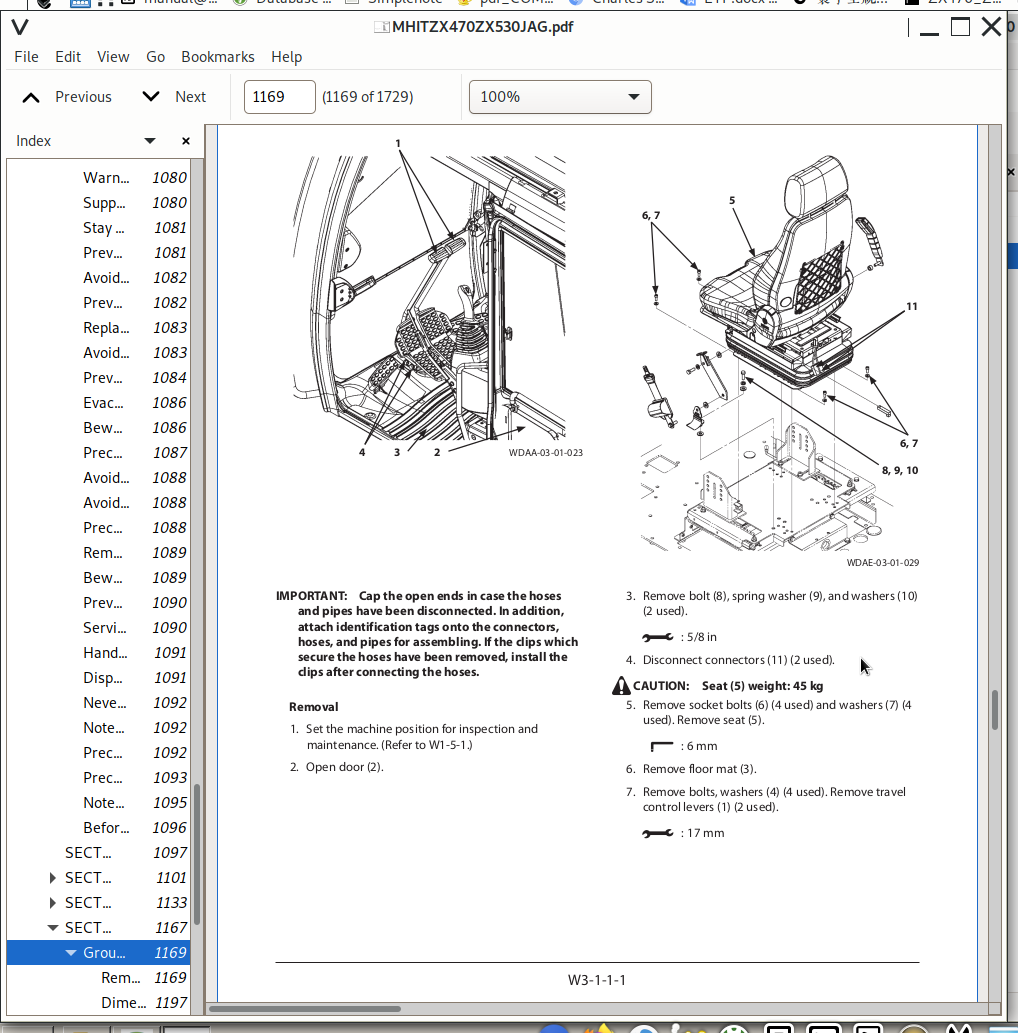
Removal and Installation of Cab.....1169
Dimensions of Cab Glass (Standard Cab).....1197
Dimensions of Cab Glass (H Cab).....1216
Group 2 Counterweight.....1219
Removal and Installation of Counterweight.....1219
Group 3 Main Frame.....1225
Removal and Installation of Main Frame.....1225
Group 4 Engine.....1235
Removal and Installation of Engine.....1235
Group 8 Pump Device.....1267
Removal and Installation of Pump Device.....1267
Disassembly of Main Pump.....1287
Assembly of Main Pump.....1292
Disassembly of Regulator for Main Pump.....1299
Assembly of Regulator for Main Pump.....1301
Disassembly of Fan Pump.....1305
Assembly of Fan Pump.....1309
Structure of Pilot Pump.....1313
Group 9 Control Valve.....1315
Removal and Installation of Control Valve.....1315
Disassembly and Assembly of Housing.....1329
Disassembly of Control Valve 4-Spool Side.....1333
Assembly of Control Valve 4-Spool Side.....1341
Disassembly of Control Valve 5-Spool Side.....1349
Assembly of Control Valve 5-Spool Side.....1356
Group 10 Swing Device.....1363
Removal and Installation of Swing Device.....1363
Disassembly of Swing Device.....1367
Assembly of Swing Device.....1373
Disassembly of Swing Motor.....1379
Assembly of Swing Motor.....1382
Group 11 Pilot Valve.....1387
Removal and Installation of Pilot Valve (Left).....1387
Removal and Installation of Pilot Valve (Right).....1399
Removal and Installation of Travel Pilot Valve.....1415
Disassembly of Pilot Valves (Right and Left).....1419
Assembly of Pilot Valves (Right and Left).....1422
Disassembly of Travel Pilot Valve.....1425
Assembly of Travel Pilot Valve.....1429
Group 12 Solenoid Valve.....1435
Removal and Installation of Pilot Shut-Off Solenoid Valve.....1435
Removal and Installation of 4-Spool Solenoid Valve Unit.....1439
Removal and Installation of 2-Spool Solenoid Valve Unit.....1443
Removal and Installation of Fan Pump Control Solenoid Valve.....1447
Disassembly of Pilot Shut-Off Solenoid Valve.....1451
Assembly of Pilot Shut-Off Solenoid Valve.....1453
Structure of 4-Spool Solenoid Valve Unit.....1455
Structure of 2-Spool Solenoid Valve Unit.....1457
Structure of Fan Pump Control Solenoid Valve.....1459
Group 13 Signal Control Valve.....1461
Removal and Installation of Signal Control Valve.....1461
Structure of Signal Control Valve.....1467
Group 14 Aftertreatment Device.....1471
Removal and Installation of Aftertreatment Device.....1471
Group 15 DEF Tank.....1479
Removal and Installation of DEF Tank.....1479
Group 16 Coolant Control Valve.....1495
Removal and Installation of Coolant Control Valve.....1495
Group 17 DEF Supply Module.....1501
Removal and Installation of DEF Supply Module.....1501
Group 19 Fan Valve.....1505
Removal and Installation of Fan Valve.....1505
Structure of Fan Valve.....1539
Group 20 Fan Motor.....1541
Removal and Installation of Fan Motor.....1541
Structure of Fan Motor.....1549
Group 21 Shockless Valve.....1551
Removal and Installation of Shockless Valve.....1551
Structure of Shockless Valve.....1553
SECTION 4 UNDERCARRIAGE.....1557
Group 1 Swing Bearing.....1559
Removal and Installation of Swing Bearing.....1559
Disassembly of Swing Bearing.....1563
Assembly of Swing Bearing.....1566
Group 2 Travel Device.....1569
Removal and Installation of Travel Device.....1569
Disassembly of Travel Device.....1573
Assembly of Travel Device.....1580
Disassembly of Travel Motor.....1589
Assembly of Travel Motor.....1593
Disassembly of Brake Valve.....1599
Assembly of Brake Valve.....1602
Group 3 Center Joint.....1607
Removal and Installation of Center Joint.....1607
Disassembly of Center Joint.....1611
Assembly of Center Joint.....1613
Replacement of Body and Spindle.....1616
Group 4 Track Adjuster.....1617
Removal and Installation of Track Adjuster.....1617
Disassembly of Track Adjuster.....1619
Assembly of Track Adjuster.....1624
Group 5 Front Idler.....1629
Removal and Installation of Front Idler.....1629
Disassembly of Front Idler.....1631
Assembly of Front Idler.....1634
Group 6 Upper and Lower Rollers.....1639
Removal and Installation of Upper Roller.....1639
Removal and Installation of Lower Roller.....1643
Disassembly of Lower Roller.....1649
Assembly of Lower Roller.....1651
Group 7 Track.....1655
Removal and Installation of Track.....1655
SECTION 5 FRONT ATTACHMENT.....1671
Group 1 Front Attachment.....1673
Removal and Installation of Front Attachment.....1673
Removal and Installation of Bushing.....1679
Group 2 Cylinder.....1681
Removal and Installation of Boom Cylinder.....1681
Removal and Installation of Arm Cylinder.....1689
Removal and Installation of Bucket Cylinder.....1697
Disassembly of Boom, Arm, and Bucket Cylinders.....1701
Assembly of Boom, Arm, and Bucket Cylinders.....1707
Group 3 Hose Rupture Valve.....1713
Removal and Installation of Hose Rupture Valve for Boom Cylinder.....1713
Removal and Installation of Hose Rupture Valve for Arm Cylinder.....1717
Structure of Hose Rupture Valve for Boom Cylinder.....1721
Structure of Hose Rupture Valve for Arm Cylinder (Bottom Side).....1723
Structure of Hose Rupture Valve for Arm Cylinder (Rod Side).....1725
SERVICE MANUAL REVISION REQUEST FORM.....1729
Hitachi ZX470-6, ZX470LC-6, ZX490H-6, ZX490LCH-6, ZX490R-6, ZX490LCR-6, ZX530LCH-6 Excavators Repair Service Manuals
![]()