
International/Navistar CF-Series, CityStar Trucks Repair Service Manual
Complete service repair manual with Electrical Wiring Diagrams for International/Navistar Models CF500, CF600, CityStar 3, CityStar 5, with all the technical information to maintain, diagnose, repair, rebuild like professional mechanics.
International/Navistar Models CF500, CF600, CityStar 3, CityStar 5 workshop service repair manual includes:
* Numbered table of contents easy to use so that you can find the information you need fast.
* Detailed sub-steps expand on repair procedure information
* Numbered instructions guide you through every repair procedure step by step.
* Troubleshooting and electrical service procedures are combined with detailed wiring diagrams for ease of use.
* Notes, cautions and warnings throughout each chapter pinpoint critical information.
* Bold figure number help you quickly match illustrations with instructions.
* Detailed illustrations, drawings and photos guide you through every procedure.
* Enlarged inset helps you identify and examine parts in detail.
PRODUCT DETAILS:
Total Pages: 7,974 pages
File Format: PDF (Internal Links, Bookmarked, Table of Contents, Searchable, Printable, high quality)
Language: English
0001027267 - 2017–2020 IC Bus RE Series Technician Manual (Service and Diagnostic), Revision 6.pdf
CTS-5123V - 3600, 3800, 4000FBC Chassis Built November 1997 through February 1999 Electrical Circuit Diagrams.pdf
0000003042 - JAC CityStar 5 (HFC1061 SERIES) Workshop Manual.pdf
0000019443 - IC Bus RE Series (Built September 2017 and After) Body Electrical Circuit Diagrams Diagrams.pdf
0000002843 - IC Bus RE Series Built November 2011 and After Body Electrical Circuit Diagrams.pdf
0000003034 - JAC CityStar 3 (HFC1041 SERIES) Workshop Manual.pdf
S08335 - RE Bus Models Built 1999 to 2006 Body Electrical Circuit DiagramsCircuit Diagrams.pdf
0000002484 - BE, CE, CE Propane Autogas, HC and RE Buses Exhaust Aftertreatment System with DPF (Supersedes S07006) Revision 2 Service Manual.pdf
0000019442 - IC Bus RE Series (Built September 2017 and After) Chassis (Cummins L9) Electrical Circuit Diagrams.pdf
0000019822 - FE and SFC Bus Series Euro III & V Circuit Diagram Manual.pdf
S47004 - CE 200 AND CE 300 BUS BODY COMPONENTS CE 200, CE 300 Service Manual.pdf
S08351 - RE Bus Series Built January 2010 to June 2011 Body Electrical Circuit Diagrams.pdf
S13036 - CF 500, CF 600 Transmission Manual.pdf
S08226XA - 3400, 3800, 4000 FBC Chassis Electrical Circuit Diagram Built October 1, 1999 and After, Supersedes CTS-5123X (April 1999).pdf
S08208Y - 3000 FE, 3000 RE Models Electrical Circuit Diagrams Built August 1, 2000 To February 29, 2004, Supersedes CTS-5216W (March 2000).pdf
S08311 - CF 500, CF 600 Build End Date January 31, 2006 Electrical Circuit Diagrams (March 2005) Service Manual.pdf
S08297 - FE 300, RE 200, RE 300 Series Built March 1, 2004 and After Electrical Circuit Diagrams.pdf
S08317 - CF 500, CF 600 Models Built February 1, 2006 to August 31, 2007 Electrical Circuit Diagrams Manual.pdf
S12023 - RE Bus Side Mount Cooling Package (Aug 2012) Service Manual.pdf
S16032 - CF 500, CF 600 Cab Service Manual.pdf
S08342 - 3100 Bus Starting October, 2009 (Mexico and Latin America Markets) Electrical Circuit Diagrams Manual.pdf
S08307 - CF 500, CF 600 Electrical (Nov 2005) Service Manual.pdf
S08356 - 3100 Bus (For Brazil Market) Starting March, 2011 Electrical Circuit Diagrams.pdf
S08334 - RE Bus Models Built July 01, 2007 and After Electrical Circuit Diagrams.pdf
S04049 - CF 500, CF 600 Brakes (Jan 2007) Service Manual.pdf
S08331 - FE 300 Models Built June 11, 2007 and After Electrical Circuit Diagrams.pdf
S08332 - CF 500, CF 600 Models Starting September 1, 2007 Electrical Circuit Diagrams Manual.pdf
S040393 - Lucas Varity _ TRW Hydraulic Antilock Brake System (Dec 2003) Service Manual.pdf
S08345 - RE Bus Models Built August 16, 2010 and After Electrical Circuit Diagrams.pdf
S07003 - Exhaust Aftertreatment and Diesel Particulate Filter (DPF) (Oct 2009) Manual.pdf
S16030 - CF 500, CF 600 Heat Ventilation Air Conditioning (HVAC) System Service Manual.pdf
S12059 - FE Bus _ 3100 Bus Radiator_Cooling System Service Manual (Brazilian Market) (Aug 2012) Service Manual.pdf
S08314 - RE 200 and RE 300 Instruments (Data Link Driven Instrument Cluster) Service Manual.pdf
S05028 - RE Bus Steering Column Assembly Service Manual (March 2012).pdf
S03014 - CF 500, CF 600 Suspension (Dec 2005) Service Manual.pdf
S03019 - Primaax Rear Air Suspension (2012) Service Manual.pdf
S14020 - CF 500, CF 600 Rear Axle Service Manual.pdf
S05023 - RE Bus Steering Column Assembly Service Manual (March 2012).pdf
S05017 - CF 500, CF 600 Steering (May 2005) Service Manual.pdf
S10019 - CF 500, CF 600 General Service Manual (May 2005).pdf
S03017 - Parasteer™ Front Air Suspension (2012) Service Manual.pdf
S12015 - Cooling System (April 2005) Service Manual.pdf
S07004 - Exhaust Aftertreatment and Diesel Particulate Filter (DPF) (Oct 2009)Aftertreatment.pdf
S07009 - Exhaust Aftertreatment System and Diesel Particulate Filter (2012) Manual.pdf
S03013 - International Ride Optimized Suspension (Dec 2005) Manual.pdf
S15002 - CF 500, CF 600 Fuel Tanks Service Manual.pdf
S08327 - 2007 - 2010 Body Controller (BC) Diagnostic Trouble Codes.pdf
S17002 - CF 500, CF 600 Wheels and Tires Manual.pdf
S12014 - Intake Air Distribution_Filtering and Charge Air Cooler (April 2005) Service Manual.pdf
S07002 - CF 500, CF 600 Exhaust System (April 2005) Service Manual.pdf
S16031 - CF 500, CF 600 Entertainment System Service Manual.pdf
S09012 - CF 500, CF 600 Front End (April 2005) Service Manual.pdf
TABLE OF CONTENTS
0000002484 - BE, CE, CE Propane Autogas, HC and RE Buses Exhaust Aftertreatment System with DPF (Supersedes S07006) Revision 2 Service Manual....1
toc....3
Summary of Changes....3
1. Description....7
1.1. Theory of Operation....14
MaxxForce® DT....14
MaxxForce® 7....14
Cummins® ISB6.7....14
PSI 8.8 LPG Engine....14
1.2. Single Horizontal / Horizontal....15
2. General Service Information....16
2.1. Exhaust Aftertreatment System Modifications....17
2.2. Diesel Particulate Filter (DPF) Cleaning....18
Diesel Particulate Filter (DPF) and Diesel Oxidation Catalyst (DOC) Inspection....18
2.3. Gaskets And Fasteners....18
2.4. Diesel Particulate Filter (DPF) Indexing....19
2.5. Decomposition Reactor Tube Cleaning....19
2.6. Diesel Exhaust Fluid (DEF) Dosing Valve Cleaning....20
2.7. Diesel Exhaust Fluid (DEF) Tank Draining....21
3. Component Replacement....23
3.1. MaxxForce® 7 OR DT Systems....23
Pressure Tubes and Pressure Sensor – Removal....23
Pressure Tubes and Pressure Sensor – Installation....24
Temperature Sensor – Removal....25
Temperature Sensor – Installation....25
Doser Control Unit (DCU) (CE and BE) – Removal....26
Doser Control Unit (DCU) (CE and BE) – Installation....26
Doser Control Unit (DCU) (HC) – Removal....27
Doser Control Unit (DCU) (HC) – Installation....27
Doser Control Unit (DCU) (RE) – Removal....28
Doser Control Unit (DCU) (RE) – Installation....28
4. Single Horizontal / Horizontal....30
4.1. MaxxForce® 7 OR DT ENGINE....30
Diesel Particulate Filter (DPF) (RE Bus) – Removal....30
Diesel Particulate Filter (DPF) (RE Bus) – Installation....31
Diesel Particulate Filter (DPF) (BE, CE, and HC Bus) – Removal....32
Diesel Particulate Filter (DPF) (BE, CE, and HC Bus) – Installation....33
5. In–Line....34
5.1. Cummins® ISB6.7 Engine....34
Diesel Particulate Filter (DPF) – Removal....34
Diesel Particulate Filter (DPF) – Installation....34
Decomposition Reactor Tube – Removal....36
Decomposition Reactor Tube – Installation....37
Selective Catalyst Reduction (SCR) Canister – Removal....38
Selective Catalyst Reduction (SCR) Canister – Installation....39
Selective Catalyst Reduction (SCR) NOx Out Sensor and Module – Removal....40
Selective Catalyst Reduction (SCR) NOx Out Sensor and Module – Installation....41
Selective Catalyst Reduction (SCR) Ammonia (NH3) Sensor Module – Removal....42
Selective Catalyst Reduction (SCR) Ammonia (NH3) Sensor Module – Installation....42
Selective Catalyst Reduction (SCR) Ammonia (NH3) Sensor – Removal....43
Selective Catalyst Reduction (SCR) Ammonia (NH3) Sensor – Installation....43
Selective Catalyst Reduction (SCR) Temperature Sensors and Module – Removal....44
Selective Catalyst Reduction (SCR) Temperature Sensors and Module – Installation....44
Diesel Oxidation Catalyst (DOC) / Diesel Particulate Filter (DPF) Temperature Sensors and Module – Removal....45
Diesel Oxidation Catalyst (DOC) / Diesel Particulate Filter (DPF) Temperature Sensors and Module – Installation....46
Diesel Particulate Filter (DPF) Differential Pressure / Outlet Pressure Sensor Module – Removal....47
Diesel Particulate Filter (DPF) Differential Pressure / Outlet Pressure Sensor Module – Installation....48
Diesel Particulate Filter (DPF) Differential Pressure Tube – Removal....49
Diesel Particulate Filter (DPF) Differential Pressure Tube – Installation....49
Diesel Particulate Filter (DPF) Differential Outlet Pressure Tube – Removal....50
Diesel Particulate Filter (DPF) Differential Outlet Pressure Tube – Installation....50
6. Switchback / Horizontal....51
6.1. Cummins® ISB6.7 Engine....51
Switchback / Horizontal....51
7. Horizontal Dual Catalytic Converters....52
7.1. PSI 8.8L LPG Engine....52
Horizontal Dual Catalytic Converters....52
8. Diesel Exhaust Fluid (DEF) System....53
8.1. Cummins® ISB6.7....53
Diesel Exhaust Fluid (DEF) Tank – Removal....53
Diesel Exhaust Fluid (DEF) Tank – Installation....55
Diesel Exhaust Fluid (DEF) Tank Wiring Harness – Removal....56
Diesel Exhaust Fluid (DEF) Tank Wiring Harness – Installation....57
Diesel Exhaust Fluid (DEF) Tank Lines – Removal....58
Diesel Exhaust Fluid (DEF) Tank Lines – Installation....59
Diesel Exhaust Fluid (DEF) Supply Module – Removal....60
Diesel Exhaust Fluid (DEF) Supply Module – Installation....61
Diesel Exhaust Fluid (DEF) Dosing Unit Filter – Removal....62
Diesel Exhaust Fluid (DEF) Dosing Unit Filter – Installation....62
Diesel Exhaust Fluid (DEF) Tank Pickup Assembly – Removal....63
Diesel Exhaust Fluid (DEF) Tank Pickup Assembly – Installation....64
Diesel Exhaust Fluid (DEF) Tank Heater Valve – Removal....66
Diesel Exhaust Fluid (DEF) Tank Heater Valve – Installation....67
Diesel Exhaust Fluid (DEF) Pressure Line and Coolant Lines – Removal....68
Diesel Exhaust Fluid (DEF) Pressure Line and Coolant Lines – Installation....70
9. Acronym List....71
tables....17
Table 2Minimum Clearance Between Exhaust System Components and Other Chassis Components....17
Table 3Acronym List....71
Table 4Torque Chart....71
0000002843 - IC Bus RE Series Built November 2011 and After Body Electrical Circuit Diagrams....72
toc....74
Table of Contents....74
2. INSTRUCTIONS AND CHARTS (CHAPTER 2)....90
2.1. Abbreviations, P. 1....90
2.2. Acronyms, P. 2....91
2.3. Circuit Diagram Instructions, P. 3....92
2.4. Circuit Number Identification And Color, P. 4....93
2.5. Circuit Number Identification And Color (Cont.), P. 5....94
2.6. Circuit Number Identification And Color (Cont.), P. 6....95
2.7. Circuit Number Identification And Color (Cont.), P. 7....96
2.8. Lamp Bulb Chart, P. 8....97
2.9. Relay Function And Wiring Guide, P. 9....98
2.10. Schematic Symbol Chart, P. 10....99
2.11. Schematic Symbol Chart (Cont.), P. 11....100
2.12. Schematic Symbol Chart (Cont.), P. 12....101
2.13. Schematic Symbol Chart (Cont.), P. 13....102
2.14. Schematic Symbol Chart (Cont.), P. 14....103
2.15. Schematic Symbol Chart (Cont.), P. 15....104
2.16. Schematic Symbol Chart (Cont.), P. 16....105
2.17. Schematic Symbol Chart (Cont.), P. 17....106
2.18. Schematic Symbol Chart (Cont.), P. 18....107
2.19. RE Bus Wiring Layout, P. 19....108
2.20. Bus Body Fuse Block, P. 20....109
3. 12 VOLT POWER DISTRIBUTION AND DATA LINK (CHAPTER 3)....110
3.1. Battery Feeds, P. 1....110
3.2. Ignition Feeds, P. 2....111
3.3. Chassis Ground, P. 3....112
3.4. Chassis Ground (Cont.), P. 4....113
3.5. Chassis Ground (Cont.), P. 5....114
3.6. Chassis Ground (Cont.), P. 6....115
3.7. Body Ground – Electric Panel, P. 7....116
3.8. Body Ground – Electric Panel (Cont.), P. 8....117
3.9. Body Ground – Electric Panel (Cont.), P. 9....118
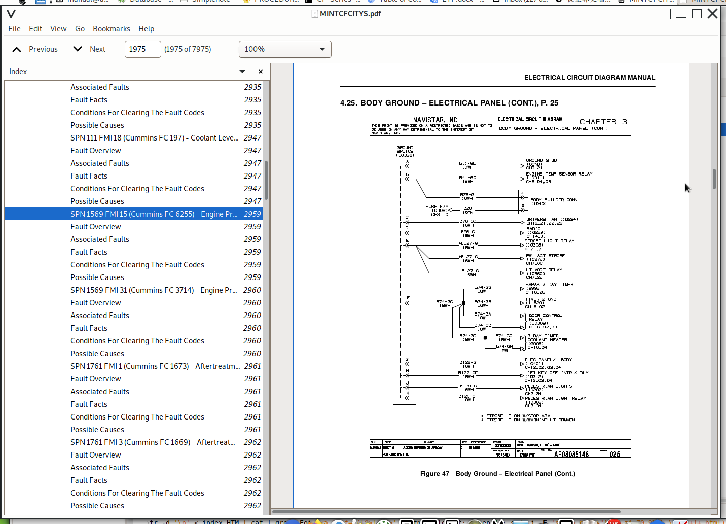
3.10. Body Ground – Electric Panel (Cont.), P. 10....119
3.11. Body Ground – Electric Panel (Cont.), P. 11....120
3.12. Body Ground – Electric Panel (Cont.), P. 12....121
3.13. Body Ground – Front Cap, P. 13....122
3.14. Body Ground – Front Cap (Cont.), P. 14....123
3.15. Body Ground – Front End, P. 15....124
3.16. Body Ground – Rear Cap, P. 16....125
3.17. Body Ground – Rear Cap (Cont.), P. 17....126
3.18. Body Ground – Left Hand Body, P. 18....127
3.19. Body Ground – Left Hand Body (Cont.), P. 19....128
3.20. Body Ground – Right Hand Body, P. 20....129
3.21. Body Ground – Right Hand Body (Cont.), P. 21....130
3.22. Body Ground – Front End, P. 22....131
3.23. Power Distribution Control Module, P. 23....132
3.24. Power Distribution Control Module (Cont.), P. 24....133
3.25. Power Distribution Control Module (Cont.), P. 25....134
3.26. Body Circuit – ACC and IGN Feed, P. 26....135
3.27. Body Circuit – Master Disconnect, P. 27....136
3.28. Body Circuit – Noise Suppression, P. 28....137
3.29. Body Circuit Fuse Block, P. 29....138
3.30. Body Circuit Fuse Block (Cont.), P. 30....139
3.31. Body Circuit Fuse Block (Cont.), P. 31....140
3.32. Body Circuit Fuse Block (Cont.), P. 32....141
3.33. Body Circuit Fuse Block (Cont.), P. 33....142
3.34. Body Circuit Fuse Block (Cont.), P. 34....143
3.35. DC Outlet, P. 35....144
3.36. J1708 Datalink, P. 36....145
3.37. J1939 Datalink Connection with WTEC Trans, P. 37....146
3.38. J1939 Datalink Connection with LCT Trans, P. 38....147
3.39. Battery Isolator, P. 39....148
3.40. J1939 Datalink Connection with WTEC Trans with Tachograph,....149
3.41. Reference Splice, P. 41....150
4. CHARGING AND CRANKING SYSTEM (CHAPTER 4)....151
4.1. Charging System, P. 1....151
4.2. Cranking System, P. 2....152
4.3. Starter Interrupt / Vandal Lock – Emergency Exit, P. 3....153
4.4. Starter Connections with 222WB, P. 4....154
5. GAUGES AND WARNING LIGHTS (CHAPTER 5)....155
5.1. Turn Signals, Douglas T / S Switch (Tilt Column), P. 1....155
5.2. Turn Signals, Douglas T / S Switch (Tilt Column) with AUX H....156
5.3. Headlight System with Tilt Column (Standard DRL), P. 3....157
5.4. Headlight System with Tilt Column (Headlight Always On), P.....158
5.5. Fuel Level Gauge, P. 5....159
5.6. Transmission Oil Temperature Gauge, P. 6....160
5.7. 300 Amp Ammeter, P. 7....161
5.8. Engine Oil Pressure, Speedometer, Tachometer, Water Tempera....162
5.9. Engine Compartment Temp Sensor / Indicator, P. 9....163
5.10. Engine Compartment and Electrical Panel Temp Sensor / Indi....164
5.11. Parking Brake and Warning Light with Air Brakes, P. 11....165
5.12. Low Oil Pressure, Hi Water Temp, Bk Warning, Low Coolant L....166
5.13. MSM Ignition / Ground, MSM Datalink, Wait to Start, Change....167
5.14. Fuel Filter Light, Water in Fuel Light, P. 14....168
5.15. Front and Rear Diagnostic / Programming Connector, P. 15....169
5.16. Headlight Warning Buzzer, P. 16....170
5.17. Stop Light Switch, P. 17....171
5.18. Tachograph, P. 18....172
5.19. Ammeter Sensor Connections, P. 19....173
5.20. Fire Suppression, P. 20....174
5.21. Rear Cap Fire Suppression and with Eng Compartment Temp Se....175
6. PUPIL WARNING LIGHT ACTIVATION (CHAPTER 6)....176
6.1. ELS – Sequential Flasher System, P. 1....176
6.2. ELS – Sequential Flasher System (Cont.), P. 2....177
6.3. Weldon Sequential Flasher System, P. 3....178
6.4. Weldon Sequential Flasher System (Cont.), P. 4....179
6.5. Weldon Non Sequential Flasher System, P. 5....180
6.6. Weldon Non Sequential Flasher System (Cont.), P. 6....181
6.7. Separate Override – Hot All Time, P. 7....182
6.8. Florida Warning Light System, P. 8....183
6.9. Florida Warning Light System (Cont.), P. 9....184
6.10. Maryland Warning Lights System, P. 10....185
6.11. Maryland Warning Lights System (Cont.), P. 11....186
6.12. Ohio Warning Light System, P. 12....187
6.13. Ohio Warning Light System (Cont.), P. 13....188
6.14. Virginia Warning Light System, P. 14....189
6.15. Virginia Warning Light System (Cont.), P. 15....190
6.16. Warning Light and Driver Alert Sign without Light Monitor,....191
6.17. Warning Light and Driver Alert Sign without Light Monitor ....192
6.18. Warning Light and Driver Alert Sign without Light Monitor ....193
6.19. Warning Lights with Lamp Monitor, P. 19....194
6.20. Driver Alert Warning Lights with Lamp Monitor, P. 20....195
6.21. Driver Alert Warning Lights with Lamp Monitor (Cont.), P. ....196
6.22. Driver Alert Warning Lights with Lamp Monitor (Cont.), P. ....197
6.23. Driver Alert Warning Lights with Lamp Monitor (Cont.), P. ....198
6.24. Driver Alert Warning Lights with Lamp Monitor (Cont.), P. ....199
6.25. Driver Alert Warning Lights with Lamp Monitor (Cont.), P. ....200
6.26. Driver Alert Warning Lights with Lamp Monitor (Cont.), P. ....201
6.27. Indicator Lights, P. 24....202
6.28. ELS – Sequential Flasher System with Sound Off Light Monit....203
6.29. Weldon – Sequential Flasher System with Sound Off Light Mo....204
7. EXTERNAL LIGHTS (CHAPTER 7)....205
7.1. Back-up Light and Alarm without Options, P. 1....205
7.2. Back-up Light and Alarm with Options, P. 2....206
7.3. Back-up Light Activated by Rear Oval Kick Out Window, P. 3....207
7.4. Destination Sign Front and Rear, P. 4....208
7.5. Fog Lights, P. 5....209
7.6. Head Lights, P. 6....210
7.7. Left Switch Panel Mounted Strobe Light Switch, P. 7....211
7.8. Strobe Light Activated by Warning Lights with Overhead Swit....212
7.9. Strobe Light Activated by Stop Arm with Overhead Switch, P.....213
7.10. Left Side Turn Lights, P. 10....214
7.11. Left Side Turn Lights (Cont.), P. 11....215
7.12. Left Side Turn Lights (Cont.), P. 11A....216
7.13. Right Side Turn Lights, P. 12....217
7.14. Right Side Turn Lights (Cont.), P. 13....218
7.15. Right Side Turn Lights (Cont.), P. 13A....219
7.16. Front Turn / Markers Lamps without Cowl Mounted Turn Lamps....220
7.17. Front Turn / Markers with Additional Turn Lamps Only on Co....221
7.18. Front Turn / Markers with Additional Park and Turn Lamps o....222
7.19. Clearance Lights, P. 15....223
7.20. Clearance Lights Front (Cont.), P. 16....224
7.21. Clearance Lights Rear (Cont.), P. 17....225
7.22. Clearance Lights (Cont.), P. 17A....226
7.23. Tail Lights without LT Monitor, P. 18....227
7.24. Tail Lights with LT Monitor, P. 19....228
7.25. Tail Lights, P. 20....229
7.26. Luggage Box Lights, P. 21....230
7.27. Standard Day Time Running Lights, P. 22....231
7.28. Special Day Time Running Lights, P. 23....232
7.29. Pedestrian Lights, P. 24....233
7.30. Auxiliary Hazard Light Switch, P. 25....234
7.31. Strobe LT MOM SW Overhead SW PNL, P. 26....235
7.32. Strobe LT Activated By Ignition, P. 27....236
7.33. Strobe Light Connections, P. 28....237
7.34. Full Time Running Lights, P. 30....238
7.35. Extra Marker Lights in Skirt, P. 31....239
7.36. Air Door Rotary SW Wired to Headlights, P. 32....240
8. INTERIOR LIGHTS (CHAPTER 8)....241
8.1. Dome Light Tied to Step Light and Ignition, P. 1....241
8.2. Dome Light Tied to Step Light and Ignition (Cont.), P. 2....242
8.3. Panel Light with Single Dimmer, P. 3....243
8.4. Panel Light with Dual Dimmer, P. 4....244
8.5. Switch Illumination, P. 5....245
8.6. Switch Illumination (Cont.), P. 6....246
8.7. Switch Illumination (Cont.), P. 7....247
8.8. Switch Illumination (Cont.), P. 8....248
8.9. Switch Illumination (Cont.), P. 9....249
8.10. Switch Illumination (Cont.), P. 10....250
8.11. Switch Illumination (Cont.), P. 11....251
8.12. Switch Illumination (Cont.), P. 12....252
8.13. Dome Light Single Switch, P. 13....253
8.14. Dome LT Split SW Overhead and L SW Panel, P. 14....254
8.15. Driver's Dome Light, P. 15....255
8.16. Driver's Dome Light (Cont.), P. 15A....256
8.17. Activity Dome Light, P. 16....257
8.18. Dome LT On with Any EMER Exit, P. 17....258
8.19. Dome LT On with Rear EMER Exit without Starter Interlock, ....259
8.20. Dome LT On with Rear EMER Exit with Starter Interlock, P. ....260
8.21. Dome LT Activated by Entrance Door, P. 20....261
8.22. Dome LT Activated by Entrance Door (Cont.), P. 20A....262
8.23. Engine Compartment Light, P. 21....263
8.24. Rear Row Dome Light, P. 22....264
8.25. Guard Dome Light, P. 23....265
8.26. Double Dome Light with Rear Row 15 Window Section, P. 24....266
8.27. Double Dome Light with Rear Row 15 Window Section (Cont.),....267
8.28. Double Dome Light with Rear Row 13 or 14 Window Section, P....268
8.29. Double Dome Light with Rear Row 13 or 14 Window Section (C....269
8.30. Double Dome Light with Rear Row 12 Window Section, P. 28....270
8.31. Double Dome Light with Rear Row 12 Window Section (Cont.),....271
8.32. Double Dome LT with Separate SW for FR and RR, and with Re....272
8.33. Double Dome LT with Separate SW for FR and RR, and with Re....273
8.34. Double Dome LT with Separate SW for FR and RR, and with Re....274
8.35. Double Dome LT with Separate SW for FR and RR, and with Re....275
8.36. Double Dome LT with Separate SW for FR and RR, and with Re....276
8.37. Double Dome LT with Separate SW for FR and RR, and with Re....277
8.38. Double Dome LT with Separate SW For FR and RR, and with Re....278
8.39. Standard Stagger Dome Light with Rear Row 15 Window Sectio....279
8.40. Standard Stagger Dome Light with Rear Row 13 or 14 Window ....280
8.41. Standard Stagger Dome Light with Rear Row 12 Window Sectio....281
8.42. STD Stagger Dome Light Front and Rear and with Rear Row 15....282
8.43. STD Stagger Dome Light with Separate SW for FR and RR with....283
8.44. STD Stagger Dome Light Front and Rear and with Rear Row 13....284
8.45. STD Stagger Dome Light with Separate SW for Front and Rear....285
8.46. Dome LT Above Each Seat with FR and Rear, P. 43....286
8.47. Dome LT Above Each Seat with FR and Rear (Cont.), P. 44....287
8.48. Dome LT Above Each Seat with FR and Rear (Cont.), P. 45....288
8.49. Compartment Light, P. 46....289
8.50. Emergency Door Light, P. 47....290
8.51. Dome LT Last Bow Sect PWR Overhead, P. 48....291
8.52. Dome LT Above Each Seat with Front and Rear, P. 49....292
8.53. Dome Lights Activated By Any Emer Exit, P. 50....293
9. STOP ARM / CROSSING GATE (CHAPTER 9)....294
9.1. Air and Electric Stop Arm Front Incandescent, P. 1....294
9.2. Air and Electric Stop Arm Front with Strobe, P. 2....295
9.3. Air and Electric Stop Arm Front and Rear Incandescent, P. 3....296
9.4. Air and Electric Stop Arm Front and Rear with Strobe, P. 4....297
9.5. Crossing Gate / Stop Arm without Cancel, P. 5....298
9.6. Crossing Gate / Stop Arm with Air Crossing Gate Cancel, P. ....299
9.7. Crossing Gate / Stop Arm with Electrical Crossing Gate Canc....300
9.8. Crossing Gate / Stop Arm with Stop Arm Cancel, P. 8....301
9.9. Crossing Gate / Stop Arm for Florida, P. 9....302
9.10. Electric and Air Crossing Gate, P. 10....303
9.11. Stop Arm / XGT with Stop Arm Cancel L SW PNL, P. 11....304
10. MIRROR SYSTEMS (CHAPTER 10)....305
10.1. Heated Only Mirror, P. 1....305
10.2. Motorized Only Mirror, P. 2....306
10.3. Heated / Motorized Mirror, P. 3....307
10.4. Heated / Motorized Mirror with 20 Minute Timer, P. 4....308
10.5. Heated Crossview Mirror and Rearview Mirror, P. 5....309
10.6. Heated and Motorized Mirror Control Switch (IKU), P. 6....310
10.7. Driver Side Heated and Motorized Mirror Control Switch (IK....311
10.8. Passenger Side Heated and Motorized Mirror Control Switch ....312
10.9. Heated and Motorized Mirror Control Switch (NGV), P. 9....313
10.10. Driver Side Heated and Motorized Mirror Control Switch (N....314
10.11. Passenger Side Heated and Motorized Mirror Control Switch....315
10.12. Left and Right Motorized Mirror Heat, P. 12....316
10.13. Heated Air Seat, P. 13....317
11. ENGINE AND ENGINE SYSTEMS (CHAPTER 11)....318
11.1. Fan Drive Control, P. 1....318
11.2. I6 Grid Heater, P. 2....319
11.3. Electronics Engine Controls 2010 Engines, P. 3....320
11.4. Electronics Engine Controls 2007 Engines, P. 4....321
11.5. Accelerator Pedal, P. 5....322
11.6. Cruise Control and Electronic Hand Throttle, P. 6....323
11.7. Electronics Engine Controls – Speedo, Tach, MAF Sensor, Ai....324
11.8. Exhaust Aftertreatment Controls System, P. 8....325
11.9. Exhaust Aftertreatment System 2010 Engine, P. 9....326
11.10. Exhaust Brakes, P. 10....327
11.11. Engine Compression Brakes, P. 11....328
11.12. Idle-Up With A/C, P. 12....329
11.13. Engine DCU Connections, P. 13....330
11.14. WIF Sensor Connections, P. 14....331
12. TRANSMISSION AND TRANSMISSION SYSTEMS (CHAPTER 12)....332
12.1. Allison with WTEC Transmission GEN IV, TCM, and Shifter IG....332
12.2. Transmission Retarder Controls, P. 2....333
12.3. Transmission Retarder Controls (Cont.), P. 3....334
12.4. Transmission Retarder Over Temp Light, P. 4....335
12.5. Allison WTEC Trans GEN IV / Check Trans Reverse Warning, P....336
12.6. Allison WTEC Trans GEN 5 Trans Bulkhead Connectors, P. 6....337
12.7. Allison WTEC Transmission GEN 5 Body Builder Connectors, P....338
12.8. Allison LCT Trans GEN IV TCM Ignition, Battery, Ground, P.....339
12.9. Allison LCT Trans GEN 5 Economy Mode SW, Range Inhibit, Ch....340
12.10. Allison WTEC TRANS GEN IV Bulkhead Connectors, P. 10....341
12.11. Allison LCT Trans GEN IV Body Builder Connectors, P. 11....342
12.12. Transmission Shift Inhibit, P. 12....343
12.13. Allison LCT Transmission GEN IV with Arens Shifter, P. 13....344
12.14. Allison LCT Transmission GEN IV with Arens Shifter (Cont.....345
12.15. Allison LCT XMSN GEN IV Economy Mode SW, Range Inhibit, C....346
12.16. Chassis 3000 RE with LCT XMSN, P. 16....347
13. CHASSIS SYSTEM (CHAPTER 13)....348
13.1. Electric Horn, P. 1....348
13.2. Air Horn with Pull Chain, with Rocker Switch, with Foot Sw....349
13.3. Air Horn Highway / City and Foot Switch, P. 3....350
13.4. Drain Valve Wiring, P. 4....351
13.5. Air Dryer (AD-9) with Air Brakes, P. 5....352
13.6. Air Dryer (AD-9) with Air Brakes, P. 6....353
13.7. ABS 6 with Bendix (Cont.), P. 7....354
13.8. ABS 6 with Bendix (Cont.), P. 8....355
13.9. Traction Sanders 5 or 10 Gallon, P. 9....356
13.10. Traction Aid – Spot Chain, P. 10....357
13.11. Dual Intermittent Windshield Wiper, P. 11....358
13.12. Dual Windshield Wiper Control, P. 12....359
13.13. Single Intermittent Windshield Wiper Control, P. 13....360
13.14. Single Windshield Wiper Control, P. 14....361
13.15. Windshield Wiper Motor, P. 15....362
13.16. Heated Wiper Blades, P. 16....363
13.17. Park Brake Interlocks, P. 17....364
13.18. Harness Chassis with ABS6 Air Brakes with ATC, P. 18....365
13.19. Harness Chassis with ABS6 Air Brakes & Brake Monitor, P. ....366
13.20. Harness Chassis with ABS6 Air Brakes 276 with ESPAR Heate....367
13.21. Seat Belt Alarm, P. 21....368
13.22. Locking Compartment with Buzzer and Start Interlock, P. 2....369
13.23. Brake Monitor, P. 23....370
14. EMERGENCY EXIT SYSTEM (CHAPTER 14)....371
14.1. Emergency Exit Buzzer, P. 1....371
14.2. Kick Out Window (Left Body) Section 1 to 8, P. 2....372
14.3. Kick Out Window (Left Body) Section 9 to 15, P. 3....373
14.4. Kick Out Window (Right Body) Section 1 to 6, P. 4....374
14.5. Kick Out Window (Right Body) Section 7 to 12, P. 5....375
14.6. Kick Out Window (Right Body) Section 13 to 15, P. 6....376
14.7. 3 Inch Red Light Over Kick Out Window (LHS) Section 1 to 4....377
14.8. 3 Inch Red Light Over Kick Out Window (LHS) Section 5 to 8....378
14.9. 3 Inch Red Light Over Kick Out Window (LHS) Section 9 to 1....379
14.10. 3 Inch Red Light Over Kick Out Window (LHS) Section 13 to....380
14.11. 3 Inch Red Light Over Kick Out Window (RHS) Section 1 to ....381
14.12. 3 Inch Red Light Over Kick Out Window (RHS) Section 7 to ....382
14.13. 3 Inch Red Light Over Kick Out Window (RHS) Section 13 to....383
14.14. Roof Hatches Section 1 to 10, P. 14....384
14.15. Roof Hatches Section 11 to 15, P. 15....385
14.16. Roof Hatch with Starter Interlock for Section 1 To 4 and ....386
14.17. Roof Hatch with Starter Interlock for Section 5 to 8, 13,....387
14.18. Left Side Emergency Door, P. 18....388
14.19. Emergency Accessory Feed Circuit for Right Side Emergency....389
14.20. Right Side Emergency Exit Door, P. 20....390
14.21. Right Side Emergency Door with Starter Interlock, P. 21....391
14.22. 3 Inch Red Light Over Right Side Emergency Door without K....392
14.23. 3 Inch Red Light Over Right Side Emergency Door with Kick....393
14.24. 3 Inch Red Light Over Right Side Emergency Door with Kick....394
14.25. 3 Inch Red Light Over Right Side Emergency Door Thru Acce....395
14.26. Rear Kick Out Window Switch and Rear Kick Out Window Vand....396
14.27. Emergency Exit Indicator Light in Cluster, P. 26....397
14.28. Splice Front Kick Out Window, P. 27....398
14.29. Rear Kick Out Window Connections, P. 28....399
14.30. Roof Hatch with Alarm and with Front Power Vent Section 2....400
14.31. Roof Hatch with Alarm and with Rear Power Vent Section 8 ....401
14.32. Roof Hatch with Rear Power Vent Section 2 and 7, P. 31....402
14.33. Roof Hatch with Rear Power Vent Section 12 and 14, P. 32....403
14.34. Splice Rear Kick Out Window, P. 33....404
15. WHEELCHAIR LIFT DOOR SYSTEM (CHAPTER 15)....405
15.1. Lift Interlock Key On with Allison LCT, P. 1....405
15.2. Lift Interlock Key On or Off with Allison LCT, P. 2....406
15.3. Lift Interlock Key On with Allison WTEC, P. 3....407
15.4. Lift Interlock Key On or Off with Rocker Switch with Allis....408
15.5. Lift Door Light, P. 5....409
15.6. Lift Door Switch Connection, P. 6....410
15.7. Lift Exterior Light, P. 7....411
15.8. Lift Interior Light, P. 8....412
15.9. Lift Door With Starter Interlock, P. 9....413
15.10. Lift Door Buzzer Connection, P. 10....414
15.11. Wheelchair Lift Interlock Connections, P. 11....415
15.12. AED Control 48 Inch with Vandal Lock, P. 12....416
15.13. Right Lift Door Connections, P. 13....417
15.14. Right Lift Door Connections (Cont.), P. 14....418
15.15. Right Lift Door Connections (Cont.), P. 15....419
15.16. Right Lift Door Connections (Cont.), P. 16....420
16. ENTRY DOOR (CHAPTER 16)....421
16.1. 2 – Position Rotary for Air Entrance Door, P. 1....421
16.2. 3-Position Rotary for Air Entrance Door, P. 2....422
16.3. 2-Position Rotary for Electric Entrance Door, P. 3....423
16.4. Electric Entrance Door with 2- or 3-Position Rotary Switch....424
16.5. Electric Entrance Door with 2- or 3-Position Rotary Switch....425
16.6. 3-Position Rotary for Electric Entrance Door, P. 5....426
16.7. Vandal Lock for Air Entrance Door, P. 6....427
16.8. Air Door with 3-Position Toggle Switch Door Control, P. 7....428
16.9. Electric Door with 3-Position Toggle Switch Door Control, ....429
16.10. Electric Door with 3-Position Toggle Switch Door Control ....430
16.11. Dump Valve Mounted in Dash or Exterior of Bus, P. 10....431
16.12. Alternate Entrance Door Control, P. 11....432
16.13. Alternate Entrance Door Control (Cont.), P. 12....433
16.14. Electric Sedan Door, P. 13....434
16.15. Alternate Entrance Door Connections, P. 14....435
17. RADIO / PA / CELLULAR – GPS (CHAPTER 17)....436
17.1. Radio and PA, P. 1....436
17.2. Speaker Wiring for QTY 2, P. 2....437
17.3. Speaker Wiring for QTY 4, P. 3....438
17.4. Speaker Wiring for QTY 6, P. 4....439
17.5. LHS Speaker Wiring for QTY 8, P. 5....440
17.6. Right Speaker Wiring for QTY 8, P. 6....441
17.7. Left Speaker Wiring for QTY 10, P. 7....442
17.8. Right Speaker Wiring for QTY 10, P. 8....443
17.9. Right Speaker Wiring for QTY 10 (Cont.), P. 8A....444
17.10. Left Speaker Wiring for QTY 12, P. 9....445
17.11. Right Speaker Wiring for QTY 12, P. 10....446
17.12. Video System, P. 11....447
17.13. Video System Term Strip, P. 12....448
17.14. Left 8 Speaker with 48 AED and 1st Located 1st Right Wind....449
17.15. Left 8 Speaker with 48 AED and 1st Located 1st Right Wind....450
17.16. Speaker Wiring for 2.4 –140 Inch Behind Stanchion, P. 15....451
17.17. Left Speaker Wiring for 2.4.6 – 140 Inch Behind Stanchion....452
17.18. Left Speaker Wiring for 6 – 140 Inch Behind Stanchion, P.....453
17.19. Left Speaker Wiring for 6 – 140 Inch Behind Stanchion (Co....454
17.20. Left Speaker Wiring for 8 – 140 Inch Behind Stanchion, P.....455
17.21. Left Speaker Wiring for 8 – 140 Inch Behind Stanchion (Co....456
17.22. Left Speaker Wiring QTY 12, P. 21....457
17.23. Left Speaker Wiring for 4 – AFT of Third Row of Seats, P.....458
17.24. Right 12 Speaker Wiring, P. 23....459
17.25. Right Speaker Wiring for 2.4 – 140 Inch Behind Stanchion,....460
17.26. Right Speaker Wiring For 6 – 140 Inch Behind Stanchion, P....461
17.27. Right Speaker Wiring 6 – 140 Inch Behind Stanchion (Cont.....462
17.28. Right Speaker Wiring For 8 – 140 Inch Behind Stanchion, P....463
17.29. Right Speaker Wiring For 8 – 140 Inch Behind Stanchion (C....464
17.30. Right Speaker Wiring For 8 – 140 Inch Behind Stanction (C....465
17.31. Right Speaker Wiring with 48 Inch AED QTY 4, P. 30....466
17.32. Right Speaker Wiring 4 – AFT of Third Row of Seats, P. 31....467
17.33. Two-Way Radio Supply Driver Compartment, P. 32....468
17.34. Dual Radio Speakers in Bulkhead, P. 33....469
18. CHILD REMINDER SYSTEM (CHAPTER 18)....470
18.1. Post Trip Inspection – CRS, P. 1....470
18.2. Child Checkmate System, P. 2....471
18.3. Bus Scan Module, P. 3....472
18.4. Monitor Post Trip Inspection, P. 4....473
18.5. Tire Carrier Winch Type, P. 5....474
19. HEATER / AIR CONDITIONING (CHAPTER 19)....475
19.1. Booster Pump, P. 1....475
19.2. Fuel Fired Heater, P. 2....476
19.3. Driver's Heater, P. 3....477
19.4. Left Front Auxiliary Heater, P. 4....478
19.5. Right Front Auxiliary Heater, P. 5....479
19.6. Left Rear Auxiliary Heater, P. 6....480
19.7. Heated Step, P. 7....481
19.8. Defog Fan or Center Blower with Left Switch Panel, P. 8....482
19.9. Defog Fan or Center Blower with Right Switch Panel, P. 9....483
19.10. Defog Fan or Center Blower with Dual Switches, P. 10....484
19.11. Driver Fan and Defog Fan or Center Blower with Left Switc....485
19.12. Driver Fan with Left SW Defog Fan or Center Blower with D....486
19.13. Driver Fan with Right Switch Defog Fan or Center Blower w....487
19.14. Defog Fan Left Switch Output, P. 14....488
19.15. Defog Fan Right Switch Output, P. 15....489
19.16. Defog Fan Right Switch Output (Cont.), P. 15A....490
19.17. Passenger Convection Heater, P. 16....491
19.18. Roof Hatches Power Vent, P. 17....492
19.19. Stepwell Heater Fan, P. 18....493
19.20. Step Defrost Heater, P. 19....494
19.21. Right Rear AUX Heater, P. 20....495
19.22. Booster Pump ESPAR with 7-Day Timer, P. 21....496
19.23. Air Dryer Heater 890 MM / 3900 MM, P. 22....497
19.24. Booster Pump with ESPAR with White Timer, P. 23....498
19.25. Booster Pump with 7-Day Timer, ESPAR, P. 24....499
19.26. Drivers Blower, P. 25....500
19.27. Webasto Heater with Timer, P. 26....501
20. CONNECTOR COMPOSITE (1 – 2500) (CHAPTER 20)....502
20.1. Connector Composite (1), P. 1....502
20.2. Connector Composite (1), P. 2....503
20.3. Intentionally Left Blank, P. 3....504
20.4. Connector Composite (1 / 2A), P. 4....505
20.5. Connector Composite (2F), P. 5....506
20.6. Connector Composite (2M), P. 6....507
20.7. Connector Composite (4M / 7M / 8M), P. 7....508
20.8. Connector Composite (9 / 10 / 11M), P. 8....509
20.9. Connector Composite (12M / 13M / 20M), P. 9....510
20.10. Connector Composite (22M / 23M), P. 10....511
20.11. Connector Composite (24 / 35M / 35X3), P. 11....512
20.12. Connector Composite (37F / 43M / 50 / 51 / 69), P. 12....513
20.13. Connector Composite (74M / 75M / 78M / 79M), P. 13....514
20.14. Connector Composite (162 / 165 / 168 / 168A), P. 14....515
20.15. Connector Composite (211M / 212M / 226F / 288X1), P. 15....516
20.16. Connector Composite (289 / 290 / 291 / 292), P. 16....517
20.17. Connector Composite (297 / 299 / 350X2), P. 17....518
20.18. Connector Composite (351 / 352 / 353), P. 18....519
20.19. Connector Composite (353 / 354), P. 18A....520
20.20. Connector Composite (382M / 383M / 383F / 384M / 386A), P....521
20.21. Connector Composite (391 / 392 / 417), P. 20....522
20.22. Connector Composite (420A / 420B / 438), P. 21....523
20.23. Connector Composite (523), P. 22....524
20.24. Connector Composite (523A / 523B / 524 / 533), P. 22A....525
20.25. Connector Composite (643 / 644F / 644M / 898), P. 23....526
20.26. Connector Composite (899 / 922 / 922A), P. 24....527
20.27. Connector Composite (925 / 926 / 996M / 997 / 998), P. 25....528
20.28. Connector Composite (1003 / 1004), P. 26....529
20.29. Connector Composite (1008 / 1023), P. 27....530
20.30. Connector Composite (1030), P. 28....531
20.31. Connector Composite (1030), P. 29....532
20.32. Connector Composite (1030P), P. 29A....533
20.33. Connector Composite (1031 / 1032 / 1033), P. 30....534
20.34. Connector Composite (1034 / 1036 / 1037 / 1038), P. 31....535
20.35. Connector Composite (1040), P. 32....536
20.36. Connector Composite (1041 / 1042A / 1042B / 1050), P. 33....537
20.37. Connector Composite (1060A / 1060B / 1061A / 1061B / 1062....538
20.38. Connector Composite (1062B / 1063A / 1063B / 1065A), P. 3....539
20.39. Connector Composite (1065B / 1066 / 1100A / 1100B), P. 36....540
20.40. Connector Composite (1111M / 1135 / 1136), P. 37....541
20.41. Connector Composite (1137 / 1138 / 1139), P. 38....542
20.42. Connector Composite (1139A / 1139B / 1140 / 1141), P. 39....543
20.43. Connector Composite (1142 / 1143A / 1146A / 1146B), P. 40....544
20.44. Connector Composite (1150 / 1150B / 1151), P. 40A....545
20.45. Connector Composite (1152 / 1153 / 1205), P. 41....546
20.46. Connector Composite (1206 / 1272 / 1408 / 1409 / 1410 / 1....547
20.47. Connector Composite (1412 / 1413 / 1415 / 1416), P. 42A....548
20.48. Connector Composite (1601M / 1601F / 1707M / 1708 / 1709)....549
20.49. Connector Composite (1800M / 1850 / 1908 / 1952 / 1952A /....550
21. CONNECTOR COMPOSITE (2501 – 6000) (CHAPTER 21)....551
21.1. Connector Composite (3043 / 3114 / 3115 / 3117), P. 1....551
21.2. Connector Composite (3118 / 3322 / 3344 / 4433), P. 2....552
21.3. Connector Composite (4800 / 5263F / 5263M), P. 3....553
21.4. Connector Composite (5432M / 5556M / 5678), P. 4....554
22. CONNECTOR COMPOSITE (6001 – 9999) (CHAPTER 22)....555
22.1. Connector Composite (6005M / 6010 / 6011 / 6012), P. 1....555
22.2. Connector Composite (6020), P. 2....556
22.3. Connector Composite (6120 / 6200 / 6260), P. 3....557
22.4. Connector Composite (6261 / 6262 / 6263), P. 4....558
22.5. Connector Composite (6308 / 6329 / 6330 / 6340), P. 5....559
22.6. Connector Composite (6341), P. 5A....560
22.7. Connector Composite (6348F / 6348F / 6348M / 6349M), P. 5B....561
22.8. Connector Composite (6400 / 6402 / 6665M / 6703 / 6705 / 6....562
22.9. Connector Composite (7150), P. 7....563
22.10. Connector Composite (7250 / 7301 / 7302 / 7303), P. 8....564
22.11. Connector Composite (7302 / 7303 / 7306F), P. 8A....565
22.12. Connector Composite (7306M / 7307A / 7307B / 7307C / 7307....566
22.13. Connector Composite (7350), P. 9A....567
22.14. Connector Composite (7600 / 7601M / 7603 / 7604 / 7607 / ....568
22.15. Connector Composite (7966 / 7966M), P. 11....569
22.16. Connector Composite (7980 / 7981 / 7982), P. 11A....570
22.17. Connector Composite (7983 / 7999M / 8721 / 8888M), P. 12....571
22.18. Connector Composite (9001 / 9003 / 9151 / 9151A), P. 12A....572
22.19. Connector Composite (9207 / 9258 / 9259 / 9260 / 9260A), ....573
22.20. Connector Composite (9263 / 9270 / 9533 / 9534), P. 14....574
22.21. Connector Composite (9535 / 9536 / 9550), P. 14A....575
22.22. Connector Composite (9850), P. 15....576
22.23. Connector Composite (9851), P. 16....577
22.24. Connector Composite (9875), P. 17....578
22.25. Connector Composite (9900 / 9901 / 9902 / 9903 / 9904), P....579
22.26. Connector Composite (9996 / 9999M), P. 19....580
23. CONNECTOR COMPOSITE (10000 – 10250) (CHAPTER 23)....581
23.1. Connector Composite (10000), P. 1....581
23.2. Connector Composite (10000), P. 2....582
23.3. Connector Composite (10003 / 10003L / 10004), P. 3....583
23.4. Connector Composite (10009 / 10010), P. 4....584
23.5. Connector Composite (10011 / 10012), P. 4A....585
23.6. Connector Composite (10013 / 10014 / 10015 / 10016 / 10017....586
23.7. Connector Composite (10018 / 10019 / 10020 / 10021 / 10022....587
23.8. Connector Composite (10024 / 10025A / 10025B / 10025C), P.....588
23.9. Connector Composite (10025D / 10026A / 10026B / 10026C), P....589
23.10. Connector Composite (10026D / 10027 / 10028 / 10028A / 10....590
23.11. Connector Composite (10029A / 10030 / 10030A / 10031 / 10....591
23.12. Connector Composite (10032 / 10033 / 10034 / 10035), P. 1....592
23.13. Connector Composite (10036 / 10038 / 10039 / 10041 / 1004....593
23.14. Connector Composite (10046 / 10046A / 10047 / 10048 / 100....594
23.15. Connector Composite (10050 / 10051 / 10070 / 10072 / 1007....595
23.16. Connector Composite (10076 / 10077 / 10078 / 10100), P. 1....596
23.17. Connector Composite (10100A / 10101 / 10102 / 10103 / 101....597
23.18. Connector Composite (10105 / 10106 / 10107), P. 15....598
23.19. Connector Composite (10108 / 10109 / 10110), P. 16....599
23.20. Connector Composite (10112 / 10113), P. 17....600
23.21. Connector Composite (10114 / 10115 / 10116), P. 18....601
23.22. Connector Composite (10117 / 10118 / 10119 / 10120 / 1012....602
23.23. Connector Composite (10122 / 10123 / 10124 / 10125), P. 2....603
23.24. Connector Composite (10127 / 10127A / 10128 / 10129 / 101....604
23.25. Connector Composite (10133 / 10135 / 10136 / 10137 / 1013....605
23.26. Connector Composite (10140 / 10141 / 10142 / 10143 / 1014....606
23.27. Connector Composite (10147 / 10153 / 10154 / 10155A / 101....607
23.28. Connector Composite (10160 / 10161 / 10176 / 10181), P. 2....608
23.29. Connector Composite (10182 / 10200), P. 25A....609
23.30. Connector Composite (10201 / 10202), P. 26....610
23.31. Connector Composite (10203), P. 26A....611
23.32. Connector Composite (10204 / 10207A / 10208), P. 27....612
23.33. Connector Composite (10209 / 10210), P. 28....613
23.34. Connector Composite (10211 / 10212 / 10213), P. 29....614
23.35. Connector Composite (10214D / 10214L / 10215 / 10216 / 10....615
23.36. Connector Composite (10218 / 10219 / 10220 / 10221 / 1022....616
23.37. Connector Composite (10225D / 10225L / 10226), P. 32....617
23.38. Connector Composite (10228 / 10229), P. 33....618
23.39. Connector Composite (10230A), P. 34....619
23.40. Connector Composite (10230B / 10231A / 10231B), P. 34A....620
23.41. Connector Composite (10232A / 10233B), P. 35....621
23.42. Connector Composite (10233A / 10233B), P. 35A....622
23.43. Connector Composite (10234A / 10234B / 10235), P. 36....623
23.44. Connector Composite (10236 / 10237), P. 37....624
23.45. Connector Composite (10238 / 10239), P. 38....625
23.46. Connector Composite (10240 / 10241A / 10241B), P. 39....626
23.47. Connector Composite (10242 / 10243 / 10243B), P. 40....627
23.48. Connector Composite (10244 / 10244B / 10245), P. 41....628
23.49. Connector Composite (10245B / 10246 / 10246B), P. 42....629
23.50. Connector Composite (10247 / 10248 / 10249 / 10250), P. 4....630
24. CONNECTOR COMPOSITE (10251 – 10500) (CHAPTER 24)....631
24.1. Connector Composite (10252 / 10253 / 10254), P. 1....631
24.2. Connector Composite (10255 / 10256 / 10257 / 10259), P. 2....632
24.3. Connector Composite (10260 / 10261 / 10262 / 10263 / 10264....633
24.4. Connector Composite (10265 / 10266 / 10267 / 10268 / 10269....634
24.5. Connector Composite (10270B / 10271 / 10272 / 10273 / 1027....635
24.6. Connector Composite (10278 / 10279 / 10280 / 10281 / 10282....636
24.7. Connector Composite (10285 / 10286 / 10287 / 10288 / 10289....637
24.8. Connector Composite (10291 / 10292 / 10293A / 10293B / 102....638
24.9. Connector Composite (10301 / 10302 / 10303 / 10304 / 10305....639
24.10. Connector Composite (10301), P. 10....640
24.11. Connector Composite (10302), P. 11....641
24.12. Connector Composite (10303 / 10304), P. 12....642
24.13. Connector Composite (10305), P. 13....643
24.14. Connector Composite (10306), P. 14....644
24.15. Connector Composite (10308), P. 15....645
24.16. Connector Composite (10309), P. 16....646
24.17. Connector Composite (10310), P. 17....647
24.18. Connector Composite (10311), P. 18....648
24.19. Connector Composite (10314 / 10315 / 10316 / 10317), P. 1....649
24.20. Connector Composite (10318 / 10319 / 10320 / 10321 / 1032....650
24.21. Connector Composite (10324 / 10325 / 10326 / 10327), P. 2....651
24.22. Connector Composite (10328 / 10329), P. 22....652
24.23. Connector Composite (10330 / 10331 / 10332 / 10333), P. 2....653
24.24. Connector Composite (10334 / 10335), P. 24....654
24.25. Connector Composite (10336 / 10337 / 10338 / 10339 / 1034....655
24.26. Connector Composite (10400), P. 26....656
24.27. Connector Composite (10400), P. 27....657
24.28. Connector Composite (10401), P. 28....658
24.29. Connector Composite (10401), P. 29....659
24.30. Connector Composite (10405), P. 30....660
24.31. Connector Composite (10406), P. 31....661
24.32. Connector Composite (10406), P. 31A....662
24.33. Connector Composite (10410 / 10411 / 10412 / 10412A), P. ....663
24.34. Connector Composite (10413 / 10413A / 10414 / 10416 / 104....664
24.35. Connector Composite (10417 / 10418 / 10419), P. 33....665
24.36. Connector Composite (10420 / 10421), P. 34....666
24.37. Connector Composite (10422 / 10423), P. 35....667
24.38. Connector Composite (10424 / 10425 / 10426 / 10427 / 1042....668
24.39. Connector Composite (10432 / 10433 / 10434 / 10435 / 1043....669
24.40. Connector Composite (10439 / 10440 / 10441 / 10442 / 1044....670
24.41. Connector Composite (10445 / 10446 / 10447 / 10448 / 1044....671
24.42. Connector Composite (10451 / 10452 / 10453), P. 40....672
24.43. Connector Composite (10457 / 10458 / 10459), P. 41....673
24.44. Connector Composite (10460 / 10461 / 10462), P. 41A....674
24.45. Connector Composite (10463 / 10463A / 10464), P. 42....675
24.46. Connector Composite (10465 / 10466 / 10467 / 10468), P. 4....676
24.47. Connector Composite (10468A / 10469 / 10470 / 10471), P. ....677
24.48. Connector Composite (10472), P. 43A....678
24.49. Connector Composite (10473 / 10474A / 10474B / 10474C / 1....679
24.50. Connector Composite (10474F / 10474G / 10474H / 10474J / ....680
24.51. Connector Composite (10474M / 10474N / 10474P / 10474R), ....681
24.52. Connector Composite (10475 / 10476 / 10479), P. 44C....682
24.53. Connector Composite (10482 / 10483 / 10483A / 10484), P. ....683
24.54. Connector Composite (10484A / 10485 / 10485A / 10486), P.....684
24.55. Connector Composite (10489 / 10489A / 10490 / 10491A), P.....685
24.56. Connector Composite (10491B / 10492), P. 47A....686
25. CONNECTOR COMPOSITE (10501 – 10750) (CHAPTER 25)....687
25.1. Connector Composite (10513), P. 1....687
25.2. Connector Composite (10514 / 10515 / 10516), P. 2....688
25.3. Connector Composite (10517 / 10518 / 10519), P. 3....689
25.4. Connector Composite (10700), P. 4....690
25.5. Connector Composite (10700), P. 5....691
25.6. Connector Composite (10700), P. 6....692
25.7. Connector Composite (10700), P. 7....693
25.8. Connector Composite (10701), P. 8....694
25.9. Connector Composite (10702), P. 9....695
25.10. Connector Composite (10703 / 10704), P. 10....696
25.11. Connector Composite (10705 / 10706), P. 11....697
25.12. Connector Composite (10709 / 10710 / 10711 / 10712), P. 1....698
25.13. Connector Composite (10713), P. 13....699
25.14. Connector Composite (10714), P. 14....700
25.15. Connector Composite (10715), P. 15....701
25.16. Connector Composite (10716 / 10717), P. 16....702
25.17. Connector Composite (10718 / 10719), P. 17....703
25.18. Connector Composite (10720 / 10721), P. 18....704
25.19. Connector Composite (10722 / 10723), P. 19....705
25.20. Connector Composite (10724 / 10725), P. 20....706
25.21. Connector Composite (10726 / 10727), P. 21....707
25.22. Connector Composite (10728 / 10729), P. 22....708
25.23. Connector Composite (10730 / 10731 / 10732 / 10733), P. 2....709
25.24. Connector Composite (10734 / 10735 / 10736 / 10737), P. 2....710
25.25. Connector Composite (10738 / 10739 / 10740 / 10741), P. 2....711
25.26. Connector Composite (10742 / 10743 / 10744), P. 26....712
25.27. Connector Composite (10745C / 10745D), P. 27....713
25.28. Connector Composite (10747C / 10747D / 10748C / 10748D), ....714
25.29. Connector Composite (10749C / 10749D), P. 29....715
26. CONNECTOR COMPOSITE (10751 – 11000) (CHAPTER 26)....716
26.1. Intentionally Left Blank, P. 1....716
26.2. Intentionally Left Blank, P. 2....717
26.3. Intentionally Left Blank, P. 3....718
26.4. Connector Composite (10757 / 10757A / 10758 / 10758A / 107....719
26.5. Connector Composite (10760 / 10760A / 10761 / 10761A), P. ....720
26.6. Connector Composite (10762 / 10763 / 10763A / 10764), P. 5....721
26.7. Connector Composite (10765A / 10765B / 10766C / 10766D / 1....722
26.8. Connector Composite (10768 / 10769C / 10769D / 10769E / 10....723
26.9. Connector Composite (10769H / 10769J), P. 7A....724
26.10. Connector Composite (10770C / 10770D / 10770E / 10770F / ....725
26.11. Connector Composite (10771E / 10771F / 10771G / 10771H / ....726
26.12. Connector Composite (10772C / 10772D / 10772E / 10772F / ....727
26.13. Connector Composite (10773C / 10773D / 10773E / 10773F), ....728
26.14. Connector Composite (10773G / 10773H / 10773J / 10773K), ....729
26.15. Connector Composite (10773L / 10773M / 10774 / 10774A / 1....730
26.16. Connector Composite (10774C / 10774D / 10774E / 10774F), ....731
26.17. Connector Composite (10774G / 10774H / 10774J / 10774K), ....732
26.18. Connector Composite (10774L / 10774N / 10774P), P. 14A....733
26.19. Connector Composite (10775C / 10775D / 10778C / 10778D), ....734
26.20. Connector Composite (10778E / 10778F / 10788H / 10788J), ....735
26.21. Connector Composite (10780 / 10781), P. 15B....736
26.22. Connector Composite (10781A / 10784 / 10785 / 10786A / 10....737
26.23. Connector Composite (10788A / 10788B / 10789), P. 17....738
26.24. Connector Composite (10795 / 10796A / 10796B / 10807A), P....739
26.25. Connector Composite (10807B / 10807C / 10807D), P. 18A....740
26.26. Connector Composite (10831 / 10832 / 10833 / 10833A), P. ....741
26.27. Connector Composite (10837 / 10838 / 10839C / 10839D), P.....742
26.28. Connector Composite (10848A / 10849A / 10850A / 10851A), ....743
26.29. Connector Composite (10852A / 10853C / 10853D / 11000), P....744
26.30. Connector Composite (11000), P. 19....745
26.31. Connector Composite (11000), P. 20....746
26.32. Connector Composite (11001 / 11003 / 11004L / 11004R), P.....747
26.33. Connector Composite (11005L / 11005R / 11006L / 11006R), ....748
26.34. Connector Composite (11007L / 11007R / 11008L / 11008R), ....749
26.35. Connector Composite (11009L / 11009R), P. 23....750
26.36. Connector Composite (11010L / 11010R / 11011L), P. 24....751
26.37. Connector Composite (11011R / 11012 / 11015 / 11016), P. ....752
26.38. Intentionally Left Blank, P. 26....753
26.39. Connector Composite (11017 / 11018 / 11019 / 11020), P. 2....754
26.40. Connector Composite (11021 / 11022 / 11023 / 11024), P. 2....755
26.41. Connector Composite (11025 / 11025A / 11025B / 11025C), P....756
26.42. Connector Composite (11025D / 11026 / 11027 / 11028), P. ....757
26.43. Connector Composite (11029 / 11031 / 11033), P. 30....758
26.44. Connector Composite (11037 / 11038 / 11044), P. 31....759
0000003034 - JAC CityStar 3 (HFC1041 SERIES) Workshop Manual....760
VIN----Vehicle Identification Number....765
02-12 HFC4DA1-2C engine HFC1041 CityStar 3.pdf....0
Chapter I Technical Characteristics of Engine....768
Section I Technical Requirements for Fuel, Oils, and Auxiliary Materials....768
I. Diesel....768
II. Engine Oil....769
III. Coolant....770
Section II Main Technical Specification of Engine....771
Section III Performance Curve of Engine....772
Section IV Main Checking and Adjustment Parameters....773
Section V Tightening Torque for Critical Bolts of Engine....774
Section VI Main Fitting Clearances and Allowable Wear Limits of Engine....778
Section VII Specification of Main Attachments and Accessories....781
Chapter II Maintenance for Main Structures of Engine....782
Section I Disassembly of Engine Assembly....782
I. Special Notices:....782
II. Disassembly Procedure....782
III. Illustration for Disassembly of Engine....783
Section II Assembly of Engine....800
I. Basic Technical Requirements for Assembly....800
II. Illustration for Assembly of Engine....801
Section III Crankshaft and Flywheel System....825
Section IV Piston and Connecting Rod Group....826
Section V Valve Distribution Mechanism....827
Section VI Lubrication System....828
Section VII Cooling System....829
Section VIII Turbocharger and Inter-Cooler System....830
Section IX EGR System....832
Section X Exhaust System....833
Chapter III Working Principle of Engine Control and Actuator Units....834
Section I Overview of Diesel Common Rail System....834
Section II Working Principle of Low Pressure Fuel Line System....836
I. Composition of low pressure fuel line:....836
II. Fuel tank....836
III. Fuel filter (including manual fuel delivery pump)....836
IV. Low pressure fuel delivery pump....837
V. Fuel pipeline....837
VI. Common malfunctions and troubleshooting for low pressure fuel line....838
Section III Working Theory of High Pressure Fuel Line....839
I. High pressure fuel line parts....839
II. High pressure pump....839
III. Fuel rail (Common rail)....839
IV. High pressure fuel pipe....840
IV. Fuel injector....840
Section IV Electronic Control Unit of High Pressure Common Rail System....841
II. Engine control unit (ECU)....854
III. Actuators....858
Chapter IV Engine Diagnosis....866
Section I. Precautions....866
1. Removal/Installation Requirements for Electronic Control Unit (ECU):....866
2. Cleaning Requirements:....866
3. All types of harness connectors and the connector for diagnostic instrument should be connected and disconnected only when the ignition switch is turned off:....866
4. Please pay attention to the following points when maintaining the fuel supply system (fuel supply pipe, fuel pump and fuel injection system):....866
5. Safety Measures....866
Section II. Maintenance Procedures....868
Section III. Fault Diagnosis....870
1. Fault Information Record....870
2. Fault Condition....870
3. Fault Type....870
4. Fault Frequency Counter....870
5. Fault Alarm....870
6. Fault Reading....870
8. Fault Detection....871
Section IV. DTC List....872
Section V. Fault Diagnosis for Electronic-Controlled Common Rail Diesel Engines....890
1.....890
3.....895
4.....899
6.....905
7.....907
8.....909
10.....913
11.....915
15.....924
17.....928
22.....937
23.....940
24.....942
26.....947
27.....949
28.....951
33.....961
04-13 LC5T28 Transmission HFC1041 CityStar 3.pdf....0
目 录 ( Catalogue)....982
06-14 Rear axle HFC1041 CityStar 3.pdf....0
②When driving, please don’t lift clutch with great force so as not to break the gears.....1026
Ⅴ Trouble Shooting....1027
1 Hub bearing dragging....1027
2 Unsmooth wheel....1027
3 Abnormal transmission sound....1028
4 Lubricating oil leakage....1028
5 Insufficient brake force....1029
07-02 Front axle HFC1041 CityStar 3.pdf....0
Check and Repair....1034
Front Wheel Hub and Brake Hub....1037
Front axle and steering knuckle....1040
09-03 Suspension HFC1041 CityStar 3.pdf....0
Overview....1049
Disassembly....1050
Reassembly....1054
Front shock absorber assembly....1056
Failure diagnosis of front suspension....1057
II. Rear suspension....1062
Overview....1062
Disassembly....1062
Reassembly....1066
Rear shock absorber assembly....1067
Failure diagnosis of rear suspension....1068
13-16 Cab HFC1041 CityStar 3.pdf....0
4.8 Malfunction Diagnosis....1122
Cab Assembly....1144
1. Front Wall Components....1144
2. Front Windshield Glass....1146
3. Rear Windshield Glass....1148
Disassembling and Assembling....1148
4. Instrument Desk....1150
5. Ceiling Trimming....1156
6. Ceiling Sundries Box....1157
7. Vehicle Door....1157
8. Hinge Assembly and Limit Stopper Assembly of Vehicle Door....1162
9. Seat....1167
10. Seat Safety Belt....1168
11. Cab Turnover and Locking Mechanism....1169
Locking Mechanism....1171
Blank Page....1047
0000003042 - JAC CityStar 5 (HFC1061 SERIES) Workshop Manual....1296
Blank Page....1401
0000019442 - IC Bus RE Series (Built September 2017 and After) Chassis (Cummins L9) Electrical Circuit Diagrams....1671
0000019443 - IC Bus RE Series (Built September 2017 and After) Body Electrical Circuit Diagrams Diagrams....1913
0000019822 - FE and SFC Bus Series Euro III & V Circuit Diagram Manual....2560
0001027267 - 2017–2020 IC Bus RE Series Technician Manual (Service and Diagnostic), Revision 6....2697
toc....2699
Table of Contents....2699
Safety Terminology....2702
Safety Instructions....2702
Work Area....2702
Safety Equipment....2702
Protective Measures....2702
Vehicle....2702
Engine....2703
Fire Prevention....2703
Batteries....2703
Compressed Air....2703
Tools....2703
Fluids Under Pressure....2704
Fuel....2704
Removal of Tools, Parts, and Equipment....2704
Brakes....2705
1. Air Brakes....2707
Disc....2707
Front....2707
Overview....2707
Rear....2708
Overview....2708
Bendix ABS....2709
4 Channel Standard....2709
Overview....2709
4 Channel with Automatic Traction Control....2710
Overview....2710
4 Channel with ESP and Automatic Traction Control....2711
Overview....2711
2. Air Systems....2712
Air Compressor....2712
Cummins 18.7 CFM....2712
Overview....2712
Drivelines....2713
1. Driveshaft / Loop....2715
Spicer®....2715
Removal....2715
Overview....2715
Special Tools....2715
Equipment Conditions....2715
Procedure....2717
Follow-On Procedure....2719
Installation....2720
Overview....2720
Special Tools....2720
Procedure....2721
Follow-on Procedure....2723
Options:....2723
Exhaust....2725
1. Aftertreatment....2727
Aftertreatment Service Procedures....2727
Horizontal with Horizontal Tail Pipe....2727
Overview....2727
Remove Single Can....2728
Special Tools....2728
Equipment Conditions....2728
Removal Procedure....2729
Follow-On Procedure....2730
Install Single Can....2732
Special Tools....2732
Torque Specifications....2732
Equipment Conditions....2732
Installation Procedure....2733
Follow-On Procedure....2734
Aftertreatment Reuse Guidelines....2735
Overview....2735
DOC, DPF and SCR Housing Reuse Guidelines....2735
DPF Media Types....2735
DOC Inspection and Reuse Guidelines....2736
Overview....2736
Special Tools....2736
Equipment Condition....2736
Inspection Procedure....2737
Reuse Guidelines....2738
DOC Inlet New....2738
DOC Inlet / Outlet - Melted....2739
DOC Inlet - Face Plugged....2740
DOC Inlet / Outlet Face Gouged....2741
Expected Outcome....2741
Follow-On Procedure....2742
DPF Inspection and Reuse Guidelines....2743
Overview....2743
Special Tools....2743
Equipment Condition....2743
Inspection Procedure....2744
Reuse Guidelines....2745
DPF Inlet - New....2745
DPF Inlet - Dirty and Useable....2746
DPF Inlet - Dirty and Useable 2....2748
DPF Inlet - Clean....2749
DPF Inlet - Gouged....2750
DPF Inlet - Ash....2751
DPF Inlet - Dark Soot Rings....2752
DPF Outlet - Soot Stains....2753
DPF Outlet - Burn Marks from Welding....2754
DPF Outlet - Excessive Soot Stains....2755
DPF Outlet - Face Cracked....2756
DPF Outlet - Coolant Staining....2757
DPF Outlet - Melted....2758
Expected Outcome....2758
Follow-On Procedure....2758
SCR Catalyst Inspection and Reuse Guidelines....2759
Overview....2759
Special Tools....2759
Equipment Condition....2759
Inspection Procedure....2760
Reuse Guidelines....2761
New Aftertreatment SCR....2761
Iron Deposits on SCR Inlet....2762
DEF Deposits on SCR Inlet....2763
Media Erosion on SCR Inlet....2764
Water Stains on SCR Inlet....2765
Expected Outcome....2765
Follow-On Procedure....2765
Single Can Indexing....2766
Overview....2766
Special Tools....2766
Equipment Condition....2766
Procedure....2766
Follow-On Procedure....2767
2. Engine Brake....2768
Compression Brake....2768
Overview....2768
Exhaust Brake....2769
Overview....2769
Electrical / Software....2771
1. Electronic Service Tools (EST)....2773
Diamond Logic® Builder....2773
Overview....2773
Selecting an Interface Cable....2775
Overview....2775
Special Tools....2775
Equipment Conditions....2775
Selection Procedure....2775
Follow-On Procedure....2776
Connecting to a Vehicle....2777
Overview....2777
Special Tools....2777
Equipment Conditions....2777
Connection Procedure....2777
Follow-On Procedure....2778
Activating Diagnostic Mode....2779
Overview....2779
Special Tools....2779
Equipment Conditions....2779
Activation Procedure....2779
Follow-On Procedure....2780
Starting a Session....2781
Overview....2781
Special Tools....2781
Equipment Conditions....2781
Starting Procedure....2781
Follow-On Procedure....2782
Viewing Fault Codes....2783
Overview....2783
Special Tools....2783
Equipment Conditions....2783
Viewing Procedure....2783
Follow-On Procedure....2783
Clearing Fault Codes....2784
Overview....2784
Special Tools....2784
Equipment Conditions....2784
Clearing Procedure....2784
Follow-On Procedure....2784
Modifying Signals Tab....2785
Overview....2785
Special Tools....2785
Equipment Conditions....2785
Modify Watched Signal Columns....2785
Modify Watched Signals....2786
Follow-On Procedure....2786
Programming Modules....2787
Overview....2787
Special Tools....2787
Equipment Conditions....2787
Programming Procedure....2788
Follow-On Procedure....2791
Input Not Recognized by Body Control Module....2792
Overview....2792
Special Tools....2792
Equipment Conditions....2792
Troubleshooting Procedure....2792
Follow-On Procedure....2793
Output Not Commanded by Body Control Module....2794
Overview....2794
Special Tools....2794
Equipment Conditions....2794
Troubleshooting Procedure....2794
Follow-On Procedure....2795
2. General Electrical Repair....2796
Electrical Connector Cleaning....2796
Overview....2796
Special Tools....2796
Specifications....2796
Equipment Conditions....2796
Cleaning Procedure....2796
Follow-On Procedure....2796
3. 12 Volt System....2797
Battery Box....2797
Passenger Side Rear Mounted— Overview....2797
Battery Disconnect....2798
Special Tools....2798
Equipment Conditions....2798
Disconnect Procedure....2798
Follow-On Procedure....2799
Battery Reconnect....2800
Special Tools....2800
Torque Specifications....2800
Equipment Conditions....2800
Reconnect Procedure....2800
Follow-On Procedure....2801
Battery Terminal Cleaning....2802
Overview....2802
Special Tools....2802
Equipment Conditions....2802
Cleaning Procedure....2803
Follow-On Procedure....2803
Charging and Starting System....2804
Overview....2804
Operational Checkout Procedure....2805
Overview....2805
Charging System....2806
Diagnostic Overview....2806
Battery Pack....2806
Alternator....2806
Battery Gauge Reading Low / Fluctuating ....2808
Overview....2808
Possible Causes....2808
Battery Gauge Reading High ....2810
Overview....2810
Possible Causes....2810
Repeated Jump Starts ....2811
Overview....2811
Possible Causes....2811
Red Battery Warning Light ....2813
Overview....2813
Possible Causes....2813
Starting System....2814
Overview....2814
Battery Pack....2814
Starter....2814
Control....2814
No Click No Crank....2816
Overview....2816
Possible Causes....2816
Click No Crank....2818
Overview....2818
Possible Causes....2818
Low Cranking Speed....2820
Overview....2820
Possible Causes....2820
Tests....2821
Overview....2821
Individual Battery Test....2822
Overview....2822
Special Tools....2822
Equipment Condition....2822
Test Setup....2822
Test Procedure....2823
Expected Outcome....2825
Follow-On Procedure....2825
Cable Drop Test....2826
Overview....2826
Special Tools....2826
Equipment Condition....2826
Test Setup....2826
Test Procedure....2826
Expected Outcome....2829
Follow-On Procedure....2829
Electrical System Test....2830
Overview....2830
Special Tools....2830
Equipment Condition....2831
Test Setup....2831
Battery Pack Test Procedure....2833
Starter System Test Procedure....2836
Charging System Test Procedure....2838
Expected Outcome....2841
Follow-On Procedure....2841
Manual Engine Bar Test....2842
Overview....2842
Special Tools....2842
Equipment Condition....2842
Test Setup....2842
Test Procedure....2842
Expected Outcome....2842
Follow-On Procedure....2842
Parasitic Draw Test....2843
Overview....2843
Special Tools....2843
Equipment Condition....2843
Test Setup....2843
Test Procedure....2843
Expected Outcome....2846
Follow-On Procedure....2846
Starter Control Circuit Test....2847
Overview....2847
Special Tools....2847
Equipment Condition....2847
Test Setup....2847
Test Procedure....2847
Follow-On Procedure....2848
Starter Input Signal Test....2849
Overview....2849
Special Tools....2849
Equipment Conditions....2849
Test Setup....2849
Test Procedure....2849
Follow-On Procedure....2850
Inspections....2851
Overview....2851
Electrical System Inspection....2852
Overview....2852
Special Tools....2852
Equipment Condition....2852
Inspection Procedure....2852
Expected Outcome....2855
Follow-On Procedure....2855
Ring Gear Inspection....2856
Overview....2856
Special Tools....2856
Equipment Conditions....2856
Inspection Procedure....2856
Expected Outcome....2857
Follow-On Procedure....2857
Service Procedures....2858
Starter Motor Removal....2858
Overview....2858
Special Tools....2858
Equipment Conditions....2858
Procedure....2860
Starter Motor Installation....2861
Overview....2861
Special Tools....2861
Procedure....2862
Follow-on Procedure....2862
Options:....2862
4. Accessories....2863
Steering Wheel Switches....2863
Cruise Control....2863
Overview....2863
5. Aftertreatment System....2864
Parked Regen Switch - Non Mulitplexed....2864
Overview....2865
Inhibit Regen Switch - Non Multiplexed....2866
Overview....2866
6. Alarms....2867
Engine Alarms....2867
Engine Oil Pressure, Engine Coolant level and Temperature....2868
Overview....2868
7. Brakes....2869
Brake Switch....2869
Overview....2869
8. Collision Mitigation Systems....2870
Bendix® Wingman® Advanced™....2870
Overview....2870
Adaptive Cruise Control (ACC)....2871
Alerts....2871
Collision Mitigation Braking....2871
Tech Tips....2873
Operational Checkout Procedure....2874
Overview....2874
Special Tools....2874
Driver Interface Unit....2876
Electrical Test....2876
Overview....2876
Special Tools....2876
Equipment Conditions....2876
Test Setup....2876
Follow-On Procedure....2878
Removal....2879
Overview....2879
Special Tools....2879
Equipment Conditions....2879
Removal Procedure....2879
Follow-On Procedure....2879
Installation....2880
Overview....2880
Special Tools....2880
Torque Specifications....2880
Equipment Conditions....2880
Installation Procedure....2880
Follow-On Procedure....2880
Radar Sensor....2881
Electrical Test....2881
Overview....2881
Special Tools....2881
Equipment Conditions....2881
Test Setup....2881
Follow-On Procedure....2883
Removal....2884
Overview....2884
Special Tools....2884
Equipment Conditions....2884
Removal Procedure....2884
Follow-On Procedure....2885
Installation....2886
Overview....2886
Special Tools....2886
Torque Specifications....2886
Equipment Conditions....2886
Installation Procedure....2886
Follow-On Procedure....2887
Adjustment....2888
Overview....2888
Special Tools....2888
Equipment Conditions....2888
Lateral Adjustment Procedure....2888
Vertical Adjustment Procedure....2890
Follow-On Procedure....2892
9. Engine....2893
Cummins....2893
Engine Ramp Non Multiplexed....2893
Overview....2893
Engine Retarder Non Multiplexed....2894
Engine Exhaust Brake Non Multiplexed....2895
Cummins Diagnostics....2896
Table Of Contents....2896
Fault Code Diagnostics....2897
Fault Code List....2897
SPN 111 FMI 1 (Cummins FC 235) - Coolant Level - Data Valid But Below Normal Operating Range - Most Severe Level....2899
Fault Overview....2899
Associated Faults....2899
Fault Facts....2899
Conditions For Clearing The Fault Codes....2899
Possible Causes....2899
SPN 111 FMI 3 (Cummins FC 195) - Coolant Level Sensor 1 Circuit - Voltage Above Normal or Shorted to High Source....2910
Fault Overview....2910
Associated Faults....2911
Fault Facts....2911
Conditions For Clearing The Fault Codes....2911
Possible Causes....2911
SPN 111 FMI 4 (Cummins FC 196) - Coolant Level Sensor 1 Circuit - Voltage Below Normal or Shorted to Low Source....2923
Fault Overview....2923
Associated Faults....2923
Fault Facts....2923
Conditions For Clearing The Fault Codes....2923
Possible Causes....2923
SPN 111 FMI 17 (Cummins FC 2448) - Coolant Level - Data Valid But Below Normal Operating Range - Least Severe Level....2935
Fault Overview....2935
Associated Faults....2935
Fault Facts....2935
Conditions For Clearing The Fault Codes....2935
Possible Causes....2935
SPN 111 FMI 18 (Cummins FC 197) - Coolant Level - Data Valid But Below Normal Operating Range - Moderately Severe Level....2947
Fault Overview....2947
Associated Faults....2947
Fault Facts....2947
Conditions For Clearing The Fault Codes....2947
Possible Causes....2947
SPN 1569 FMI 15 (Cummins FC 6255) - Engine Protection Torque Derate - Data Valid But Above Normal Operating Range - Least Severe Level....2959
Fault Overview....2959
Associated Faults....2959
Fault Facts....2959
Conditions For Clearing The Fault Codes....2959
Possible Causes....2959
SPN 1569 FMI 31 (Cummins FC 3714) - Engine Protection Torque Derate - Condition Exists....2960
Fault Overview....2960
Associated Faults....2960
Fault Facts....2960
Conditions For Clearing The Fault Codes....2960
Possible Causes....2960
SPN 1761 FMI 1 (Cummins FC 1673) - Aftertreatment 1 Diesel Exhaust Fluid Tank Level - Data Valid But Below Normal Operating Range - Most Severe Level....2961
Fault Overview....2961
Associated Faults....2961
Fault Facts....2961
Conditions For Clearing The Fault Codes....2961
Possible Causes....2961
SPN 1761 FMI 3 (Cummins FC 1669) - Aftertreatment 1 Diesel Exhaust Fluid Tank Level Sensor Circuit - Voltage Above Normal or Shorted to High Source....2962
Fault Overview....2962
Associated Faults....2962
Fault Facts....2962
Conditions For Clearing The Fault Codes....2962
Possible Causes....2962
SPN 1761 FMI 4 (Cummins FC 1668) - Aftertreatment 1 Diesel Exhaust Fluid Tank Level Sensor Circuit - Voltage Below Normal or Shorted to Low Source....2963
Fault Overview....2963
Associated Faults....2963
Fault Facts....2963
Conditions For Clearing The Fault Codes....2963
Possible Causes....2963
SPN 1761 FMI 9 (Cummins FC 4677) Aftertreatment 1 Diesel Exhaust Fluid Tank Level - Abnormal Update Rate ....2964
Fault Overview....2964
Associated Faults....2964
Fault Facts....2964
Conditions For Clearing The Fault Codes....2964
Possible Cause....2964
SPN 1761 FMI 10 (Cummins FC 4769) - Aftertreatment 1 Diesel Exhaust Fluid Tank Level Sensor - Abnormal Rate of Change....2969
Fault Overview....2969
Associated Faults....2969
Fault Facts....2969
Conditions For Clearing The Fault Codes....2969
Possible Causes....2969
SPN 1761 FMI 11 (Cummins FC 4739) - Aftertreatment 1 Diesel Exhaust Fluid Tank Level Sensor - Root Cause Not Known....2972
Fault Overview....2972
Associated Faults....2972
Fault Facts....2972
Conditions For Clearing The Fault Codes....2972
SPN 1761 FMI 13 (Cummins FC 4732) - Aftertreatment 1 Diesel Exhaust Fluid Tank Level Sensor - Out of Calibration....2973
Fault Overview....2973
Associated Faults....2973
Fault Facts....2973
Conditions For Clearing The Fault Codes....2973
Possible Causes....2973
SPN 1761 FMI 17 (Cummins FC 3497) - Aftertreatment 1 Diesel Exhaust Fluid Tank Level - Data Valid But Below Normal Operating Range - Least Severe Level....2974
Fault Overview....2974
Associated Faults....2974
Fault Facts....2974
Conditions For Clearing The Fault Codes....2974
Possible Causes....2974
SPN 1761 FMI 18 (Cummins FC 3498) - Aftertreatment 1 Diesel Exhaust Fluid Tank Level - Data Valid But Below Normal Operating Range -Moderately Severe Level ....2975
Fault Overview....2975
Associated Faults....2975
Fault Facts....2975
Conditions For Clearing The Fault Codes....2975
Possible Causes....2975
SPN 3031 FMI 2 (Cummins FC 1679) - Aftertreatment 1 Diesel Exhaust Fluid Tank Temperature - Data Erratic, Intermittent, or Incorrect....2976
Fault Overview....2976
Associated Faults....2976
Fault Facts....2976
Conditions For Clearing The Fault Codes....2976
Possible Causes....2976
SPN 3031 FMI 3 (Cummins FC 1678) - Aftertreatment 1 Diesel Exhaust Fluid Tank Temperature Sensor - Voltage Above Normal or Shorted to High Source ....2978
Fault Overview....2978
Associated Faults....2978
Fault Facts....2978
Conditions For Clearing The Fault Codes....2978
Possible Causes....2978
SPN 3031 FMI 4 (Cummins FC 1677) - Aftertreatment 1 Diesel Exhaust Fluid Tank Temperature Sensor - Voltage Below Normal or Shorted to Low Source....2979
Fault Overview....2979
Associated Faults....2979
Fault Facts....2979
Conditions For Clearing The Fault Codes....2979
Possible Causes....2979
SPN 3031 FMI 9 (Cummins FC 4572) - Aftertreatment 1 Diesel Exhaust Fluid Tank Temperature - Abnormal Update Rate....2980
Fault Overview....2980
Associated Faults....2980
Fault Facts....2980
Conditions For Clearing The Fault Codes....2980
Possible Cause....2980
SPN 3031 FMI 11 (Cummins FC 4737) - Aftertreatment 1 Diesel Exhaust Fluid Tank Temperature - Root Cause Not Known....2985
Fault Overview....2985
Associated Faults....2985
Fault Facts....2985
Conditions For Clearing The Fault Codes....2985
Possible Causes....2985
SPN 3031 FMI 13 (Cummins FC 4731) - Aftertreatment 1 Diesel Exhaust Fluid Tank Temperature Sensor - Out of Calibration....2986
Fault Overview....2986
Associated Faults....2986
Fault Facts....2986
Conditions For Clearing The Fault Codes....2986
Possible Causes....2986
SPN 3364 FMI 2 (Cummins FC 3878) - Aftertreatment Diesel Exhaust Fluid Quality - Data Erratic, Intermittent, or Incorrect....2987
Fault Overview....2987
Associated Faults....2987
Fault Facts....2987
Conditions For Clearing The Fault Codes....2987
Possible Causes....2987
SPN 3364 FMI 3 (Cummins FC 1686) - Aftertreatment Diesel Exhaust Fluid Quality Sensor Circuit - Voltage Above Normal or Shorted to High Source....2988
Fault Overview....2988
Associated Faults....2988
Fault Facts....2988
Conditions For Clearing The Fault Codes....2988
Possible Cause....2988
SPN 3364 FMI 4 - (Cummins 1685) - Aftertreatment Diesel Exhaust Fluid Quality Sensor Circuit - Voltage Below Normal or Shorted to Low Source....2990
Fault Overview....2990
Associated Faults....2990
Fault Facts....2990
Conditions For Clearing The Fault Codes....2990
Possible Cause....2990
SPN 3364 FMI 9 (Cummins FC 3868) - Aftertreatment Diesel Exhaust Fluid Quality - Abnormal Update Rate....2992
Fault Overview....2992
Associated Faults....2992
Fault Facts....2992
Conditions For Clearing The Fault Codes....2992
Possible Cause....2992
SPN 3364 FMI 10 (Cummins FC 4277) - Aftertreatment Diesel Exhaust Fluid Quality - Abnormal Rate of Change ....2997
Fault Overview....2997
Associated Faults....2997
Fault Facts....2997
Conditions For Clearing The Fault Codes....2997
Possible Causes....2997
SPN 3364 FMI 11 (Cummins FC 1715) - Aftertreatment Diesel Exhaust Fluid Quality - Root Cause Not Known....3000
Fault Overview....3000
Associated Faults....3000
Fault Facts....3000
Conditions For Clearing The Fault Codes....3000
Possible Causes....3000
SPN 3364 FMI 13 (Cummins FC 1714) - Aftertreatment Diesel Exhaust Fluid Quality - Out of Calibration....3001
Fault Overview....3001
Associated Faults....3001
Fault Facts....3001
Conditions For Clearing The Fault Codes....3001
Possible Causes....3001
SPN 3364 FMI 15 (Cummins FC 4842) - Aftertreatment Diesel Exhaust Fluid Quality - Data Valid But Above Normal Operating Range - Least Severe Level....3002
Fault Overview....3002
Associated Faults....3002
Fault Facts....3002
Conditions For Clearing The Fault Codes....3002
Possible Causes....3002
SPN 3364 FMI 18 (Cummins FC 3867) - Aftertreatment Diesel Exhaust Fluid Quality - Data Valid But Below Normal Operating Range - Moderately Severe Level....3004
Fault Overview....3004
Associated Faults....3004
Fault Facts....3004
Conditions For Clearing The Fault Codes....3004
Possible Causes....3004
SPN 3521 FMI 11 (Cummins FC 4768) - Aftertreatment 1 Diesel Exhaust Fluid Property - Root Cause Not Known....3006
Fault Overview....3006
Associated Faults....3006
Fault Facts....3006
Conditions For Clearing The Fault Codes....3006
Possible Causes....3006
SPN 3521 FMI 16 (Cummins FC 6765) - Aftertreatment Diesel Exhaust Fluid Property - Data Valid But Above Normal Operating Range - Moderately Severe Level....3007
Fault Overview....3007
Associated Faults....3007
Fault Facts....3007
Conditions For Clearing The Fault Codes....3007
Possible Causes....3007
SPN 3521 FMI 18 (Cummins FC 6766) - Aftertreatment Diesel Exhaust Fluid Property - Data Valid But Below Normal Operating Range - Moderately Severe Level....3009
Fault Overview....3009
Associated Faults....3009
Fault Facts....3009
Conditions For Clearing The Fault Codes....3009
Possible Causes....3009
SPN 3521 FMI 31 (Cummins FC 4235) - Aftertreatment 1 Diesel Exhaust Fluid Property- Condition Exists....3011
Fault Overview....3011
Associated Faults....3011
Fault Facts....3011
Conditions For Clearing The Fault Codes....3011
Possible Causes....3011
SPN 4096 FMI 31 (Cummins FC 3547) - Aftertreatment Diesel Exhaust Fluid Tank Empty - Condition Exists....3013
Fault Overview....3013
Associated Faults....3013
Fault Facts....3013
Conditions For Clearing The Fault Codes....3013
Possible Causes....3013
SPN 5246 FMI 0 (Cummins FC 3712) - Aftertreatment SCR Operator Inducement - Data Valid But Above Normal Operating Range - Most Severe Level....3014
Fault Overview....3014
Associated Faults....3014
Fault Facts....3014
Conditions For Clearing The Fault Codes....3014
Possible Causes....3014
SPN 5246 FMI 15 (Cummins FC 4134) - Aftertreatment SCR Operator Inducement - Data Valid But Above Normal Operating Range - Least Severe Level....3015
Fault Overview....3015
Associated Faults....3015
Fault Facts....3015
Conditions For Clearing The Fault Codes....3015
Possible Causes....3015
SPN 5246 FMI 16 (Cummins FC 6254) - Aftertreatment SCR Operator Inducement - Data Valid But Above Normal Operating Range - Moderately Severe Level....3016
Fault Overview....3016
Associated Faults....3016
Fault Facts....3016
Conditions For Clearing The Fault Codes....3016
Possible Causes....3016
Tests and Inspections....3017
Overview....3017
DEF Head Unit Coolant Line Routing Inspection....3018
Overview....3018
Tools Required....3018
Equipment Condition....3018
Inspection Procedure....3018
Expected Outcome....3019
DEF Quality Test....3020
Overview....3020
Tools Required....3020
Equipment Condition....3020
Test Procedure....3020
Expected Outcome....3021
DEFTHV Coolant Flow Test....3022
Overview....3022
Tools Required....3022
Equipment Condition....3022
Test Setup....3022
Test Procedure....3022
Expected Outcome ....3022
10. Exterior Lighting....3023
Headlights....3023
DRL Non-Multiplexed....3023
Overview....3023
11. Instrumentation / Gauges....3024
Gauges - Non Multiplexed....3024
DEF Level (500K)....3024
Diagnostic Overview....3024
12. Seats....3025
Seat Belt Indicator....3025
13. Roll Stability....3026
Bendix....3026
Roll Stability....3026
Diagnostic Overview....3026
14. Transmission....3027
Allison ....3027
Neutral Confirmation GEN 2 Archiecture....3027
Overview....3027
Engines....3029
1. Block Heater....3031
Overview....3031
2. Cooling System....3033
Cooling Package....3033
Overview....3033
Cooling Package External Cleaning....3034
Special Tools....3034
Equipment Conditions....3034
Charge Air Cooler (CAC) Cleaning....3035
Front of Radiator Cleaning....3035
Follow-On Procedure....3035
Deaeration Tank Inspection....3036
Special Tools....3036
Equipment Conditions....3036
Setup....3036
Inspection Procedure....3037
Follow-On Procedure....3038
Check Coolant Condition....3039
Special Tools....3039
Equipment Conditions....3039
Setup....3039
Coolant Check Procedure....3040
Follow-On Procedure....3041
Coolant Pressure Check Procedure....3042
Special Tools....3042
Equipment Conditions....3042
Setup....3042
Pressure Check Procedure....3043
Follow-On Procedure....3045
Cooling Package Flush Procedure....3046
Special Tools....3046
Equipment Conditions....3046
Preparation....3047
Coolant Filter Flush, if Applicable....3047
Flush Thermostat Housing....3048
Front Heater Core Flush....3048
Rear Heater Core Flush....3049
DEF Heater Core Flush....3049
Front and Rear Heater Core Rinse....3050
DEF Heater Rinse....3051
Radiator and Engine Rinse....3051
Final Rinse....3052
Follow-On Procedure....3053
Coolant Drain Procedure....3054
Special Tools....3054
Equipment Conditions....3054
Coolant Drain Procedure....3055
Follow-On Procedure....3057
Options:....3057
Deaeration Tank....3058
Removal....3058
Overview....3058
Special Tools....3058
Equipment Conditions....3058
Procedure....3059
Follow-on Procedure....3059
Installation....3060
Overview....3060
Special Tools....3060
Procedure....3061
Follow-on Procedure....3061
Rear Bumper....3062
Removal....3062
Overview....3062
Special Tools....3062
Equipment Conditions....3062
Procedure....3063
Follow-On Procedure....3066
Options:....3066
Installation....3067
Overview....3067
Special Tools....3067
Equipment Conditions....3067
Procedure....3068
Follow-On Procedure....3072
Options:....3072
Power Steering Reservoir....3073
Relocation....3073
Overview....3073
Special Tools....3073
Equipment Conditions....3073
Procedure....3074
Follow-On Procedure....3075
Options:....3075
Reinstallation....3076
Overview....3076
Special Tools....3076
Procedure....3077
Follow-On Procedure....3078
Options:....3078
Fan Drive Idler Pulley....3079
Removal....3079
Overview....3079
Special Tools....3079
Equipment Conditions....3079
Procedure....3080
Follow-On Procedure....3082
Options:....3082
Installation....3083
Overview....3083
Special Tools....3083
Equipment Conditions....3083
Procedure....3084
Follow-On Procedure....3086
Options:....3086
Heat Shrink Clamp Removal....3087
Radiator Hose - Upper....3088
Removal....3088
Overview....3088
Special Tools....3088
Equipment Conditions....3088
Procedure....3089
Follow-on Procedure....3090
Installation....3091
Overview....3091
Special Tools....3091
Procedure....3092
Follow-On Procedure....3093
Options:....3093
Radiator Hose - Lower....3094
Removal....3094
Overview....3094
Special Tools....3094
Equipment Conditions....3094
Procedure....3095
Follow-on Procedure....3096
Installation....3097
Overview....3097
Special Tools....3097
Procedure....3098
Follow-on Procedure....3099
Charge Air Cooler Hose - Inlet....3100
Removal....3100
Overview....3100
Special Tools....3100
Equipment Conditions....3100
Procedure....3101
Follow-On Procedure....3105
Options:....3105
Installation....3106
Overview....3106
Special Tools....3106
Procedure....3107
Follow-On Procedure....3111
Options:....3111
Charge Air Cooler Hose- Outlet....3112
Removal....3112
Overview....3112
Special Tools....3112
Equipment Conditions....3112
Procedure....3113
Follow-On Procedure....3114
Options:....3114
Installation....3115
Overview....3115
Special Tools....3115
Procedure....3116
Follow-On Procedure....3117
Options:....3117
Cooling Package....3118
Removal....3118
Overview....3118
Special Tools....3118
Equipment Conditions....3118
Procedure....3119
Follow-On Procedure....3126
Charge Air Cooler (CAC)....3127
Removal....3127
Overview....3127
Special Tools....3127
Equipment Conditions....3127
Procedure....3128
Follow-on Procedure....3129
Installation....3130
Overview....3130
Special Tools....3130
Equipment Conditions....3130
Procedure....3131
Radiator....3133
Removal....3133
Overview....3133
Special Tools....3133
Equipment Conditions....3133
Procedure....3135
Follow-On Procedure....3137
Installation....3138
Overview....3138
Special Tools....3138
Procedure....3139
Follow-on Procedure....3141
Cooling Package....3143
Installation....3143
Overview....3143
Special Tools....3143
Procedure....3144
Follow-on Procedure....3152
Coolant Fill Procedure....3153
Special Tools....3153
Equipment Conditions....3153
Vacuum Fill Procedure....3154
Follow-On Procedure....3157
Options:....3157
Cummins Charge Air Cooler (CAC)....3158
Overview....3158
Removal....3159
Special Tools....3159
Equipment Conditions....3159
Removal Procedure....3160
Follow-On Procedure....3161
Cleaning....3162
Special Tools....3162
Equipment Conditions....3162
Off-chassis Pressure Test....3163
Charge Air Cooler (CAC) Cleaning Management System (CMS) Installation....3164
Cleaning Procedure....3165
Charge Air Cooler (CAC) Cleaning Management System (CMS) Removal....3166
Follow-On Procedure....3166
Flush....3167
Special Tools....3167
Equipment Conditions....3167
Off-chassis Pressure Test....3167
Charge Air Cooler (CAC) Cleaning Management System (CMS) Installation....3169
Flush Procedure....3170
Charge Air Cooler (CAC) Cleaning Management System (CMS) Removal....3171
Follow-On Procedure....3171
Installation....3172
Special Tools....3172
Torque Specifications....3172
Equipment Conditions....3172
Installation Procedure....3173
Follow-On Procedure....3174
Pressure Test....3175
Special Tools....3175
Equipment Conditions....3175
Test Setup....3175
Test Procedure....3176
Follow-On Procedure....3178
3. Fan and Shroud....3181
Cummins®....3181
Cummins ® Fan....3181
Alignment Procedure....3181
4. Horton Fan Drive....3182
Modulator (Viscous)....3182
Overview....3182
Modulator Removal....3183
Special Tools....3183
Equipment Conditions....3183
Removal Procedure....3184
Follow-On Procedure....3185
Modulator Installation....3186
Special Tools....3186
Torque Specifications....3186
Equipment Conditions....3186
Installation Procedure....3187
Follow-On Procedure....3188
Fan Gearbox Removal....3189
Special Tools....3189
Equipment Conditions....3189
Removal Procedure....3189
Follow-On Procedure....3191
Fan Gearbox Installation....3192
Special Tools....3192
Torque Specifications....3192
Equipment Conditions....3192
Installation Procedure....3193
Follow-On Procedure....3194
Fan Gearbox Adjustment....3195
Overview....3195
Special Tools....3195
Equipment Conditions....3196
Adjustment Procedure ....3197
Fan Gearbox Adjustment Procedure ....3198
Follow-On Procedure....3201
Transmissions....3203
1. Automatic Transmissions....3205
Allison....3205
B-300 Series....3205
Overview....3205
B-400 Series....3206
Overview....3206
2500 Series....3208
Overview....3208
3000 Series....3209
Overview....3209
Removal....3211
Overview....3211
Special Tools....3211
Equipment Conditions....3211
Procedure....3212
Installation....3214
Overview....3214
Special Tools....3214
Procedure....3215
Follow-On Procedure....3216
Options:....3216
Removal....3217
Overview....3217
Special Tools....3217
Equipment Conditions....3217
Procedure....3218
Installation....3221
Overview....3221
Special Tools....3221
Procedure....3222
Follow-on Procedure....3226
Options:....3226
Removal....3228
Overview....3228
Special Tools....3228
Equipment Conditions....3228
Procedure....3230
Follow-On Procedure....3237
Installation....3238
Overview....3238
Special Tools....3238
Equipment Conditions....3238
Procedure....3239
Follow-on Procedure....3246
2. Transmission Oil Cooler....3249
Direct Mount Cooler....3249
Removal....3249
Special Tools....3249
Equipment Conditions....3249
Removal Procedure....3249
Follow-On Procedure....3250
Installation....3251
Special Tools....3251
Torque Specification....3251
Equipment Conditions....3251
Installation Procedure....3252
Follow-On Procedure....3252
Direct Mount Cooler Flush....3253
Special Tools....3253
Equipment Conditions....3253
Flush Procedure....3253
Follow-On Procedure....3254
Hydraulic Retarder....3255
Overview....3255
Rear Axle and Suspension....3257
1. Air Suspensions....3259
IROS (International Ride Optimized Suspension)....3259
Single Axle....3259
Overview....3259
Air Ride Spring....3261
Removal....3261
Overview....3261
Special Tools....3261
Equipment Conditions....3261
Removal Procedure....3262
Follow-On Procedure....3262
Installation....3263
Overview....3263
Special Tools....3263
Equipment Conditions....3263
Installation Procedure....3264
Follow-On Procedure....3264
Main Support Bushing....3265
Removal....3265
Overview....3265
Special Tools....3265
Equipment Conditions....3265
Removal Procedure....3266
Follow-On Procedure....3266
Installation....3267
Overview....3267
Special Tools....3267
Torque Specifications....3267
Equipment Conditions....3267
Installation Procedure....3268
Follow-On Procedure....3268
Main Support Member....3269
Removal....3269
Overview....3269
Special Tools....3269
Equipment Conditions....3269
Removal Procedure....3270
Follow-On Procedure....3270
Installation....3271
Overview....3271
Special Tools....3271
Equipment Conditions....3271
Installation Procedure....3272
Follow-On Procedure....3273
Shock Absorber....3274
Removal....3274
Overview....3274
Special Tools....3274
Equipment Conditions....3274
Removal Procedure....3275
Follow-On Procedure....3275
Installation....3276
Overview....3276
Special Tools....3276
Equipment Conditions....3276
Installation Procedure....3277
Follow-On Procedure....3277
Torque Rod....3278
Removal....3278
Overview....3278
Special Tools....3278
Equipment Conditions....3278
Removal Procedure....3278
Follow-On Procedure....3279
Installation....3280
Overview....3280
Special Tools....3280
Torque Specification....3280
Equipment Condition....3280
Installation Procedure....3280
Follow-On Procedure....3281
U-bolt Installation ....3282
Overview....3282
Special Tools....3282
Torque Specifications....3282
Equipment Condition....3282
Installation Procedure....3283
Follow-On Procedure....3284
Ride Height Adjustment Procedure....3285
Overview....3285
Special Tools....3285
Specifications....3285
Equipment Conditions....3285
Procedure....3285
Follow-On Procedure....3288
Travel exceeds specification:....3288
Travel is less than specification:....3289
Fuel Tanks....3291
1. DEF Tank....3293
DEF Doser....3293
Removal....3293
Special Tools....3293
Equipment Conditions....3293
Removal Procedure....3294
Follow-on Procedure....3294
Installation....3295
Special Tools....3295
Torque Specifications....3295
Equipment Conditions....3295
Installation Procedure....3297
DEF Tank....3298
Overview....3298
DEF....3298
DEF Tank....3298
DEF Supply Module....3298
DEF Tank Pickup Assembly....3299
DEF Lines....3299
DEF Coolant Lines....3299
DEF Tank Heater Valve....3299
DEF Line Heater....3299
Inspection....3300
Special Tools....3300
Equipment Condition....3300
Inspection Procedure....3300
Follow-on Procedure....3300
Remove....3301
Special Tools....3301
Equipment Conditions....3301
Removal Procedure....3302
Follow-on Procedure....3305
Install....3306
Special Tools....3306
Torque Specifications....3306
Equipment Condition....3306
Installation Procedure....3306
Follow-on Procedure....3308
DEF Tank Filter....3310
Remove....3310
Special Tools....3310
Equipment Conditions....3310
Removal Procedure....3311
Follow-on Procedure....3311
Install....3312
Special Tools....3312
Equipment Condition....3312
Installation Procedure....3313
Follow-on Procedure....3313
DEF Head Unit....3314
Remove....3314
Special Tools....3314
Equipment Conditions....3314
Removal Procedure....3315
Follow-on Procedure....3315
Install....3316
Special Tools....3316
Equipment Conditions....3316
Installation Procedure....3317
Follow-on Procedure....3317
DEF Supply Module....3318
Removal ....3318
Special Tools....3318
Equipment Conditions....3318
Removal Procedure....3319
Follow-on Procedure....3320
Installation....3321
Special Tools....3321
Torque Specifications....3321
Equipment Conditions....3321
Installation Procedure....3322
Follow-on Procedure....3323
2. Fuel / Water Separator....3324
Racor....3324
Overview....3324
tables....2720
Torque Specifications....2720
Procedures....2774
Torque Specifications....2802
Diagnostic Section....2807
Diagnostic Section....2821
Battery Type....2824
Description....2824
Battery Chemistry....2824
Description....2824
Battery Type....2833
Description....2833
Battery Chemistry....2834
Description....2834
Individual Battery Test RESULTS....2836
Recommended Action....2836
Starting System RESULTS....2837
Recommended Action....2837
RESULTS....2841
Recommended Action....2841
Diagnostic Section....2851
Torque Specifications....2861
Test Procedure....2876
Test Procedure....2881
Specifications....2888
Overview....3025
Torque Specifications....3060
Torque Specifications....3067
Torque Specifications....3076
Torque Specifications....3083
Torque Specifications....3091
Torque Specifications....3097
Torque Specifications....3106
Torque Specifications....3115
Torque Specifications....3130
Torque Specifications....3138
Torque Specifications....3143
Torque Specifications....3189
Torque Specifications....3196
Torque Specifications....3214
Torque Specifications....3221
Torque Specifications....3238
Service Procedures....3260
Torque Specifications....3263
Torque Specifications....3271
Torque Specifications....3276
CTS-5123V - 3600, 3800, 4000FBC Chassis Built November 1997 through February 1999 Electrical Circuit Diagrams....3328
Blank Page....3328
Blank Page....3329
S03013 - International Ride Optimized Suspension (Dec 2005) Manual....3446
S03014 - CF 500, CF 600 Suspension (Dec 2005) Service Manual....3481
S03017 - Parasteer™ Front Air Suspension (2012) Service Manual....3522
S03019 - Primaax Rear Air Suspension (2012) Service Manual....3549
S040393 - Lucas Varity _ TRW Hydraulic Antilock Brake System (Dec 2003) Service Manual....3584
S04049 - CF 500, CF 600 Brakes (Jan 2007) Service Manual....3698
S05017 - CF 500, CF 600 Steering (May 2005) Service Manual....3770
S05023 - RE Bus Steering Column Assembly Service Manual (March 2012)....3815
toc....3817
Table of Contents....3817
1. DESCRIPTION....3819
1.1. Steering Column Assembly....3819
1.2. STEERING COLUMN....3820
1.3. PINCH BOLT....3820
1.4. Lubrication....3820
2. REMOVAL AND INSTALLATION....3821
2.1. STEERING WHEEL....3822
Steering Wheel – Removal....3822
Steering Wheel – Installation....3823
2.2. STEERING COLUMN....3825
Steering Column – Removal....3825
Steering Column – Installation....3826
2.3. STEERING SHAFT....3827
Steering Shaft – Removal....3827
Steering Shaft – Installation....3829
2.4. UNIVERSAL JOINT....3830
Universal Joint – Removal....3831
Universal Joint – Installation ....3834
3. ALIGNMENT....3836
3.1. Steering Wheel....3836
tables....3836
Table 1Torque Chart....3836
S05028 - RE Bus Steering Column Assembly Service Manual (March 2012)....3837
toc....3839
Table of Contents....3839
1. Description....3841
1.1. Steering Wheel....3841
1.2. Universal Joint....3841
1.3. Steering Shaft....3841
1.4. Steering Column....3842
1.5. Pinch Bolt....3842
1.6. Lubrication....3842
1.7. Power Steering Reservoir....3842
2. Removal and Installation....3843
2.1. Steering Wheel....3844
Steering Wheel – Removal....3844
Steering Wheel – Installation....3845
2.2. Steering Column....3847
Steering Column – Removal....3847
Steering Column – Installation....3849
2.3. Steering Shaft....3850
Steering Shaft – Removal....3850
Steering Shaft – Installation....3852
2.4. Universal Joint....3853
Universal Joint – Removal....3854
Universal Joint – Installation ....3857
2.5. Power Steering Reservoir....3859
Power Steering Reservoir – Removal....3859
Power Steering Reservoir – Installation....3859
3. Checks and Adjustments....3860
3.1. Power Steering Reservoir Fill Procedure....3860
Power Steering Reservoir – Fill....3860
3.2. Steering Wheel....3860
Steering Wheel – Check....3860
Steering Wheel – Adjust....3861
tables....3862
Table 1Torque Chart....3862
S07002 - CF 500, CF 600 Exhaust System (April 2005) Service Manual....3863
S07003 - Exhaust Aftertreatment and Diesel Particulate Filter (DPF) (Oct 2009) Manual....3879
S07004 - Exhaust Aftertreatment and Diesel Particulate Filter (DPF) (Oct 2009)Aftertreatment....3960
S07009 - Exhaust Aftertreatment System and Diesel Particulate Filter (2012) Manual....3980
toc....3982
Table of Contents....3982
1. DESCRIPTION....3984
1.1. Theory of Operation....3985
MaxxForce® 5, 7, DT, 9, and 10....3985
2. GENERAL SERVICE INFORMATION....3986
2.1. Exhaust System Modifications....3987
2.2. DIESEL PARTICULATE FILTER (DPF) CLEAN / REPLACE....3988
2.3. GASKET....3988
2.4. DIESEL PARTICULATE FILTER INDEXING....3989
3. REMOVAL AND INSTALLATION....3990
3.1. PRESSURE SENSOR and PRESSURE TUBES....3990
Pressure Sensor and Pressure Tubes – Removal....3990
Pressure Sensor and Pressure Tubes – Installation....3991
3.2. TEMPERATURE SENSOR....3992
Temperature Sensor – Removal....3992
Temperature Sensor – Installation....3992
3.3. DIESEL PARTICULATE FILTER (DPF)....3993
Diesel Particulate Filter (DPF) – Removal....3993
Diesel Particulate Filter (DPF) – Installation....3994
tables....3987
Table 1Minimum Clearance Between Exhaust System Components and O....3987
Table 2Torque Chart....3995
S08208Y - 3000 FE, 3000 RE Models Electrical Circuit Diagrams Built August 1, 2000 To February 29, 2004, Supersedes CTS-5216W (March 2000)....3996
S08226XA - 3400, 3800, 4000 FBC Chassis Electrical Circuit Diagram Built October 1, 1999 and After, Supersedes CTS-5123X (April 1999)....4176
S08297 - FE 300, RE 200, RE 300 Series Built March 1, 2004 and After Electrical Circuit Diagrams....4402
S08307 - CF 500, CF 600 Electrical (Nov 2005) Service Manual....4669
S08311 - CF 500, CF 600 Build End Date January 31, 2006 Electrical Circuit Diagrams (March 2005) Service Manual....4832
S08314 - RE 200 and RE 300 Instruments (Data Link Driven Instrument Cluster) Service Manual....5029
S08317 - CF 500, CF 600 Models Built February 1, 2006 to August 31, 2007 Electrical Circuit Diagrams Manual....5125
S08327 - 2007 - 2010 Body Controller (BC) Diagnostic Trouble Codes....5215
S08331 - FE 300 Models Built June 11, 2007 and After Electrical Circuit Diagrams....5348
S08332 - CF 500, CF 600 Models Starting September 1, 2007 Electrical Circuit Diagrams Manual....5478
S08334 - RE Bus Models Built July 01, 2007 and After Electrical Circuit Diagrams....5597
S08335 - RE Bus Models Built 1999 to 2006 Body Electrical Circuit DiagramsCircuit Diagrams....5726
S08335a....5726
S08335b....5853
S08335c....5964
S08342 - 3100 Bus Starting October, 2009 (Mexico and Latin America Markets) Electrical Circuit Diagrams Manual....6072
S08345 - RE Bus Models Built August 16, 2010 and After Electrical Circuit Diagrams....6134
S08351 - RE Bus Series Built January 2010 to June 2011 Body Electrical Circuit Diagrams....6271
S08356 - 3100 Bus (For Brazil Market) Starting March, 2011 Electrical Circuit Diagrams....6822
S09012 - CF 500, CF 600 Front End (April 2005) Service Manual....6892
S10019 - CF 500, CF 600 General Service Manual (May 2005)....6899
S12014 - Intake Air Distribution_Filtering and Charge Air Cooler (April 2005) Service Manual....6964
S12015 - Cooling System (April 2005) Service Manual....6977
S12023 - RE Bus Side Mount Cooling Package (Aug 2012) Service Manual....7002
toc....7004
Table of Contents....7004
1. DESCRIPTION....7006
1.1. Cooling Package....7006
Charge Air Cooler....7006
Radiator....7007
Spider Cage....7007
Fan Shroud....7007
1.2. Deaeration Tank....7008
1.3. Hydraulic System....7009
Hydraulic Reservoir and Filter....7009
Hydraulic Pump....7010
Hydraulic Fan Drive Motor....7010
Hydraulic Oil Cooler....7010
2. REMOVE AND INSTALL PROCEDURES....7011
2.1. Coolant Drain, Pressure Test, and Fill Procedures....7012
Coolant Drain Procedure (Recommended)....7014
Pressure Test Procedure (Recommended)....7016
Coolant Fill Procedure (Recommended)....7017
Coolant Drain Procedure (Optional)....7019
Coolant Fill Procedure (Optional)....7020
2.2. Deaeration Tank....7022
Deaeration Tank – Removal....7022
Deaeration Tank – Installation....7025
2.3. Hydraulic Filter....7026
Hydraulic Filter – Removal....7026
Hydraulic Filter – Installation....7026
2.4. Hydraulic Reservoir....7027
Hydraulic Reservoir – Removal....7027
Hydraulic Reservoir – Installation....7029
2.5. Hydraulic Pump....7030
Hydraulic Pump – Removal....7030
Hydraulic Pump – Installation....7034
2.6. Fan Drive Motor Solenoid....7035
Fan Drive Motor Solenoid – Removal....7035
Fan Drive Motor Solenoid – Installation....7035
2.7. Hydraulic Fan Drive Motor....7036
Hydraulic Fan Drive Motor – Removal....7036
Hydraulic Fan Drive Motor – Installation....7040
2.8. Hydraulic Oil Cooler....7041
Hydraulic Oil Cooler – Removal....7041
Hydraulic Oil Cooler – Installation....7044
2.9. Radiator Fan....7045
Radiator Fan – Removal....7045
Radiator Fan – Installation....7048
2.10. Cooling Package....7049
Cooling Package – Removal....7049
Cooling Package – Disassembly....7058
Cooling Package – Assembly....7067
Cooling Package – Installation....7069
tables....7071
Table 1Torque Chart....7071
S12059 - FE Bus _ 3100 Bus Radiator_Cooling System Service Manual (Brazilian Market) (Aug 2012) Service Manual....7073
toc....7075
Table of Contents....7075
1. Description....7077
1.1. Deaeration Tank....7078
1.2. Fan and Fan Drive....7078
1.3. Fan Shroud....7078
1.4. Radiator....7078
1.5. Charge Air Cooler....7078
2. Removal and Installation....7079
2.1. Cooling Package Cleaning Procedure....7080
2.2. Deaeration Tank....7082
Deaeration Tank – Removal....7082
Deaeration Tank – Installation....7083
2.3. Fan Belt....7084
Fan Belt – Removal....7084
Fan Belt – Installation....7084
2.4. Fan and Fan Drive....7085
Fan and Fan Drive – Removal....7085
Fan and Fan Drive – Installation....7086
2.5. Fan Shroud....7087
Fan Shroud – Removal....7087
Fan Shroud – Installation....7087
2.6. Radiator Hoses....7088
Heat Shrink Clamp – Removal....7088
Heat Shrink Clamp – Installation....7089
Radiator Hoses – Removal....7091
Radiator Hoses – Installation....7092
2.7. Charge Air Cooler....7093
Charge Air Cooler – Removal....7093
Charge Air Cooler – Installation....7094
2.8. Radiator Assembly....7095
Radiator Assembly – Removal....7095
Radiator Assembly – Installation....7096
2.9. Radiator Core....7097
Radiator Core – Removal....7097
Radiator Core – Installation....7098
tables....7099
Table 1Torque Chart....7099
S13036 - CF 500, CF 600 Transmission Manual....7100
S14020 - CF 500, CF 600 Rear Axle Service Manual....7437
S15002 - CF 500, CF 600 Fuel Tanks Service Manual....7477
S16030 - CF 500, CF 600 Heat Ventilation Air Conditioning (HVAC) System Service Manual....7495
S16031 - CF 500, CF 600 Entertainment System Service Manual....7603
S16032 - CF 500, CF 600 Cab Service Manual....7620
S17002 - CF 500, CF 600 Wheels and Tires Manual....7738
S47004 - CE 200 AND CE 300 BUS BODY COMPONENTS CE 200, CE 300 Service Manual....7754
International/Navistar CF-Series, CityStar Trucks Repair Service Manual
![]()