
International IC Bus 3000-Series Repair Service Manual
Complete service repair manual with Electrical Wiring Diagrams for International IC Bus 3000-Series, with all the technical information to maintain, diagnose, repair, rebuild like professional mechanics.
IC Bus 3000-Series workshop service repair manual includes:
* Numbered table of contents easy to use so that you can find the information you need fast.
* Detailed sub-steps expand on repair procedure information
* Numbered instructions guide you through every repair procedure step by step.
* Troubleshooting and electrical service procedures are combined with detailed wiring diagrams for ease of use.
* Notes, cautions and warnings throughout each chapter pinpoint critical information.
* Bold figure number help you quickly match illustrations with instructions.
* Detailed illustrations, drawings and photos guide you through every procedure.
* Enlarged inset helps you identify and examine parts in detail.
0000975235 - 2017-2020 IC Bus CE Series Technician Manual (Service and Diagnostics), Revision 9.pdf
97H00601205 - MWM DIAGNOSTICS MANUAL ACTEON SERIES 4.12 AND 6.12 TCE Engines Service Manual.pdf
0001027267 - 2017-2020 IC Bus RE Series Technician Manual (Service and Diagnostics), Revision 6.pdf
CTS-5123V - 3600, 3800, 4000FBC Chassis (Built November 1997 through February 1999) Electrical Circuit Diagrams.pdf
S13008 - 6 Speed Transmissions Eaton Series FS-5106 and FS-6206 Supersedes CTS-5179 (June 1996) Service Manual.pdf
0000020182 - 2016 - 2019 IC Bus BE _ CE Series Electrical Circuit Diagrams.pdf
0000002601 - 3200, RXT, DuraStar, TranStar, TranStar Natural Gas, WorkStar Series (Built May, 2010-) Electrical Circuit Diagrams (Supersedes S08343).pdf
S082503 - 3200 (Oct 2000 to May 2003) Electrical Troubleshooting Manual.pdf
S08291 - BE 200, CE Bus, CE 200 and CE 300 Series Built March, 2004 Electrical Circuit Diagrams.pdf
0000019443 - IC Bus RE Series (Built September 2017 and After) Body Electrical Circuit Diagrams.pdf
0000002843 - IC Bus RE Series Built November 2011 and After Body Electrical Circuit Diagrams.pdf
S05015Y - Power Steering Gear_ Sheppard M-Series, Supersedes CTS-5262 (Sept 2000) Service Manual.pdf
0000003601 - 2011 - 2015 IC Bus BE _ CE Series Electrical Circuit Diagrams (Supersedes S08377).pdf
S08290 - BE 200, CE 200, CE 300 Model Electrical System Troubleshooting Guide Service Manual.pdf
S47001Y - IC BUS Service Manual.pdf
S08335 - RE Bus Models Built 1999 to 2006 Body Electrical Circuit Diagrams.pdf
S082504 - 3200 (May 2003 to Feb 2007) Electrical Troubleshooting Manual.pdf
0000003361 - IC Bus BE _ CE Models Radiator _ Cooling System Service Manual.pdf
S082503A - Electrical System Troubleshooting Guide Models Built After 05_20_2003 (Apr 2004).pdf
S082504 - Electrical System Troubleshooting Guide Models Built 05_20_2003 to 02_28_2007 (Jan 2008).pdf
S082503 - Electrical System Troubleshooting Guide Models Built 10_16_2000 to 05_20_2003 (Jan 2008) Service Manual.pdf
0000002601 - 3200, RXT, DuraStar - 4100, 4300, 4400, TranStar Natural Gas (NG), TranStar - 8500, 8600, WorkStar - 7300, 7400, 7500, 7600, 7700 Electrical Circuit Diagram Manual.pdf
S05003Y - Power Steering Gear_ TRW _ ROSS-TAS 40, 55, 65 and 85, Supersedes CTS-5215 (Sept 2000) Service Manual.pdf
S08286 - IC Bus Models Built March 1, 2000 and After (Body) Electrical Circuit Diagrams.pdf
S08322 - 3200 (March 2007 to March 2008) Wiring Diagrams.pdf
0000017581 - 3600, 3800, 4000FBC Chassis Built November 1997 through February 1999 Electrical Circuit Diagrams.pdf
S08322 - 3200, 4100, 4200, 4300, 4400, 7300, 7400, 7500, 8500, 8600, RXT Models Built March 1, 2007 to March 18, 2008 Electrical Circuit Diagrams.pdf
0000002484 - BE, CE, CE Propane Autogas, HC and RE Buses Exhaust Aftertreatment System with DPF (Supersedes S07006) Service Manual.pdf
0000019442 - IC Bus RE Series (Built September 2017 and After) Chassis Electrical Circuit Diagrams.pdf
S08315 - 3200, 4100, 4200, 4300, 4400, 7300, 7400, 7500, 7600, 7700, 8500, 8600, MXT, RXT Models Built Oct. 1, 2005 to Feb. 28, 2007 Electrical Circuit Diagrams.pdf
0000002242 - IC Bus AE Series Electrical Circuit Diagrams.pdf
S10024 - Eaton Hybrid System Service Manual (Oct 2009).pdf
S47006 - BE 200 BUS FRONT END AND BODY COMPONENTS Service Manual.pdf
S14014 - SINGLE REDUCTION, SINGLE SPEED AXLES_ SPICER D135-S, F155-S, F170-S SERIES (Supersedes CTS-5233) Service Manual.pdf
S08298 - 3300 Model Electrical System Troubleshooting Guide (Jan 2008) Service Manual.pdf
S10028 - IC Bus CE Bus Eaton Hybrid System Service Manual (May 2011) Service Manual.pdf
S47009 - IC Bus AE Model Body ComponentsService Manual.pdf
S08320 - BE, CE Series Built August, 2006 Through February, 2007 (Chassis Only) Electrical Circuit Diagrams.pdf
S13010 - 5 Speed Transmissions Spicer ES62-5A, ES62-5D, ES67-5A and ES67-5D Supersedes CTS-5182 (June 1996) Service Manual.pdf
S08300 - 3300 Model Built March, 2004 to December, 2006 Electrical Circuit Diagrams (Jan 2007) Service Manual.pdf
0000002842 - 3200, DuraStar, TranStar, WorkStar, and RXT Models Built March, 2008 to May 16, 2010 Electrical Circuit Diagrams (Supersedes S08337).pdf
S08299 - 3300 Model Built March, 2004 to December, 2006 Electrical Circuit Diagrams (Jan 2007).pdf
S08266 - IC Bus Electrical System Troubleshooting Guide Built 03_01_2000 (Aug 2000) Service Manual.pdf
S082854 - 3200 (2004 to 2005) Wiring Diagrams.pdf
S47003 - FE 300 BUS BODY COMPONENTSService Manual.pdf
S14008T - SINGLE SPEED REAR AXLE_ INTERNATIONAL (Supersedes CTS-5108T) Service Manual.pdf
S082853 - 3200 (Sep 2003) Wiring Diagrams.pdf
0000019822 - FE and SFC Bus Series Euro III & V Circuit Diagram ManualCircuit Diagrams.pdf
S082853 - 3200, 4200, 4300, 4400, 7300, 7400, 7500, 7600, 8500, 8600 Models Built September 16, 2003 to March 10, 2004 Electrical Circuit Diagrams.pdf
S47005 - RE 200, RE 300 BUS BODY COMPONENTS Service Manual.pdf
S08337 - 3200 (March 2008 to March 2010) Wiring Diagrams.pdf
S13006H - 6 Speed Transmissions International Model ES52-7A and ESO65-7A 6-Plus Service Manual.pdf
S47004 - CE 200 AND CE 300 BUS BODY COMPONENTS Service Manual.pdf
S08351 - RE Bus Series Built January 2010 to June 2011 Body Electrical Circuit Diagrams.pdf
S08226XA - 3400, 3800, 4000 FBC Chassis Electrical Circuit Diagram Built October 1, 1999 and After, Supersedes CTS-5123X (April 1999).pdf
S08296 - FE 300, RE 200, RE 300 Build Date 03_01_2004 Electrical System Troubleshooting Guide (Feb 2007).pdf
S13009 - 5 Speed Transmissions Spicer ES43-5 and ES53-5 Supersedes CTS-5181 (March 1996) Service Manual.pdf
S16034 - HEAT VENTILATION AIR CONDITIONING (HVAC), TXV System, March 2007 - 2009 3200, 4100, 4200, 4300, 4400, 7300, 7400, 7500, 7600, 7700, 8500, 8600 Models, CXT, DuraStar, TranStar, WorkStar and RXT.pdf
0000002842 - 3200 (2008 to 2010) Wiring Diagrams.pdf
S13012 - 5 Speed Transmissions Spicer ES60-5 Supersedes CTS-5184 (March 1996) Service Manual.pdf
S16046 - 3200 Bus, DuraStar, TerraStar, TranStar, WorkStar Models Heat Ventilation Air Conditioning (HVAC) for 2010 Service Manual.pdf
S16046 - 2010 HVAC Service Manual.pdf
S09009 - Hood, Grille, Fenders and Bumper - CE 200, CE 300 (March 2004) Service Manual.pdf
S08340 - RE Bus Models Built January 2007 and After Body Electrical Circuit Diagrams.pdf
S11003 - Spicer 14-Inch (355.6 mm) Stamped Angle-Spring Clutch Supersedes CTS-5140 (March 1996) Service Manual.pdf
S16025 - HEAT VENTILATION AIR CONDITIONING (HVAC), Orifice Tube System, Pre-March 2007 - 3200, 4100, 4200, 4300, 4400, 7300, 7400, 7500, 7600, 7700, 8500, 8600 Service Manual.pdf
S16025 - 2005 HVAC Manual.pdf
S13011 - 5 Speed Transmissions Spicer ES70-5 Supersedes CTS-5183 (March 1996) Service Manual.pdf
S08324 - 3200, 4100, 4200, 4300, 4400, 7300, 7400, 7500, 7600, 7700, 8500, 8600, CXT, DuraStar, RXT, TranStar, and WorkStar Models Built After March 01, 2007 Electrical System Troubleshooting Guide Diagnostic Trouble Codes.pdf
S082852A - 3200, 4200, 4300, 4400, 7300, 7400, 7500, 7600, 8500, 8600 Models Built October 1, 2002 to September 15, 2003 Electrical Circuit Diagrams (Oct 2002).pdf
S08269 - 3000FE, 3000RE Electrical System Troubleshooting Guide Built Date 11_17_1997 Supersedes CTS-5282 (Jan 2000).pdf
S12023 - RE Bus Side Mount Cooling Package (Aug 2012) Service Manual.pdf
S09010 - Hood, Grille, Fenders and Bumper - 3300 (March 2004) Service Manual.pdf
S10018 - 3200 Integrated Mobility (IM) Option Service Manual (Oct 2005).pdf
S08003 - Allison WT Transmission Electronic Controls, Supersedes CTS-5090 (June 1996) Service Manual.pdf
0000650450 - IC Bus™ Propane Autogas CE Series Radiator _ Cooling SystemService Manual.pdf
S04038 - EC-17 Antilock Traction Controller, Supersedes CTS-5292 (Aug 1998) Service Manual.pdf
0000002841 - IC Bus RE Series Built November 2011 and After Body Electrical Circuit Diagrams.pdf
S04048 - Full Power Hydraulic ABS Brake System (Jan 2007)Service Manual.pdf
S04051 - Full Power Hydraulic ABS Brake System (Dec 2006) Service Manual.pdf
S11004 - Spicer 14 Inch (350 mm) Solo Clutch Supersedes CTS-5256 (March 1996) Service Manual.pdf
S04050 - Full Power Hydraulic ABS Brake System (Dec 2006)Service Manual.pdf
S09019 - IC Bus AC _ AE Model Hood, Grille, Fenders, and Bumper (2012) Service Manual.pdf
S12039 - IC Bus AC Model Radiator _ Cooling System (June 2012) Service Manual.pdf
0000944045 - SFC Bus™ Series Stripped Chassis ISB EPA04 Only Electrical Circuit Diagrams.pdf
ITEC DCU MWM SCR Post-Treatment Wiring Diagram Acteon Series 4.12 AND 6.12 TCE Euro VEngine Diagnostic Forms.pdf
S11015 - 3000 RE _ 3100 Midi Bus Hydraulic Clutch Service Manual (Feb 2010) Service Manual.pdf
S04024 - Antilock Air Brake System_ Bendix, Supersedes CTS-5114 (April 1996) Service Manual.pdf
S04025 - Antilock Air Brake System_ Bendix, Supersedes CTS-5115 (June 1996) Service Manual.pdf
S08364 - BE, CE Hybrid Bus Models Built November, 2010 Electrical Circuit DiagramsCircuit Diagrams.pdf
S16003 - Repair Instructions for Fiberglass and Plastic (ABS) Material (Formerly CTS-5173) Service Manual.pdf
S08334 - RE Bus Models Built July 01, 2007 and After Electrical Circuit Diagrams.pdf
ITEC ECU MWM Wiring Diagram Acteon Series 4.12 and 6.12 TCE Euro VEngine Diagnostic Forms.pdf
S040393 - Lucas Varity _ TRW Hydraulic Antilock Brake System (Dec 2003) Service Manual.pdf
S08345 - RE Bus Models Built August 16, 2010 and After Electrical Circuit Diagrams.pdf
S14015 - 2 SPEED REAR AXLES_ SPICER (Supersedes CTS-5193) Service Manual.pdf
S04016K - Caliper Disc Brakes, Supersedes CTS-5009K (March 1996) Service Manual.pdf
S07003 - Exhaust Aftertreatment and Diesel Particulate Filter (DPF) (Oct 2009) Aftertreatment.pdf
S04045 - Meritor _ WABCO Hydraulic ABS for Medium-Duty Trucks, Buses and Motor Home Chassis (June 2000) Service Manual.pdf
S12059 - FE Bus _ 3100 Bus Radiator_Cooling System Service Manual (Brazilian Market) (Aug 2012) Service Manual.pdf
S08314 - RE 200 and RE 300 Instruments (Data Link Driven Instrument Cluster) Service Manual.pdf
S08313 - IC Bus and FE 300 Bus Instruments (Data Link Driven Instrument Cluster) Service Manual.pdf
S08155X - Instruments (New Data Link Driven Instrument Cluster), Supersedes CTS-5228 (Oct 1999) Service Manual.pdf
S04007 - Reconditioning Brake Drums and Shoes, Supersedes CTS-5085 (March 1996) Service Manual.pdf
S05028 - 3100 Bus _ FE Bus Steering Column Assembly Brazilian Market (Aug 2012) Service Manual.pdf
S08154X - Speedometer _ Tachometer Diagnostics and Service, Supersedes CTS-5257 (Oct 1999) Service Manual.pdf
S03019 - Primaax Rear Air Suspension (2012) Service Manual.pdf
S04003R - Air Compressor_ Bendix TU-Flo 550 and TU-Flo 750, Supersedes CTS-5056R (March 1996) Service Manual.pdf
S04005 - Cam Air Foundation Brakes, Supersedes CTS-5060 (March 1996) Service Manual.pdf
S08034X - Instruments, Supersedes CTS-5088K (Oct 1999) Service Manual.pdf
S04004 - Air Compressor_ Bendix 2150, Supersedes CTS-5058 (March 1996) Service Manual.pdf
S03001K - Air Suspension with Tapered Leaf Springs, Supersedes CTS-5025K (March 1996) Service ManualM.pdf
S05006W - Power Steering Pump_ Eaton Model BB135 R, L, Supersedes CTS-5160 (Jan 1998) Service Manual.pdf
S03017 - Parasteer™ Front Air Suspension (2012) Service Manual.pdf
S12008 - Radiator, Removal and Replacement (2012) Service Manual.pdf
S04018W - Reconditioning Rotors, Supersedes CTS-5086W (June 1998) Service Manual.pdf
S04029 - Antilock Brakes_Traction Control_ Bendix - Principles, Operation and Service, Supersedes CTS-5246 (March 1996) Service Manual.pdf
S04011 - Air Compressor_ Midland Models EL-1300 and EL-1600, Supersedes CTS-5146 (March 1996) Service Manual.pdf
s04010 - Air Compressor_ Bendix TU-FLO 501, Supersedes CTS-5145 (March 1996) Service Manual.pdf
S07004 - Exhaust Aftertreatment and Diesel Particulate Filter (DPF) (Oct 2009).pdf
S03016 - Stabil-Ride™ Suspension (2010) Service Manual.pdf
S07009 - Exhaust Aftertreatment System and Diesel Particulate Filter (2012) Service Manual.pdf
S04020X - Double Diaphragm MGM Spring Brake, Supersedes CTS-5107X (Sept 1998) Service Manual.pdf
S11007R - Clutch Control Linkage Supersedes CTS-5061R (March 1996) Service Manual.pdf
S04017Y - Hydro-Max Brake Booster and Master Cylinder, Supersedes CTS-5018K (Dec 2000) Service Manual.pdf
S05013 - Steering Column Assembly, Standard and Tilt, Supersedes CTS-5168 (April 1996) Service Manualpdf
S08036 - Starting Motors (Delco-Remy), Supersedes CTS-5054 (March 1996) Service Manual.pdf
S03009 - MOR _ RYDE Rubber Spring Suspension, Supersedes CTS-5177 (March 1996) Service Manual.pdf
S03013 - International Ride Optimized Suspension (Dec 2005) Service Manual.pdf
S08327 - 2007 - 2010 Body Controller (BC) Diagnostic Trouble Codes Manual.pdf
S11002 - Spicer 13-Inch (310 mm) and 14-Inch (350 mm) Angle-Ring Single Plate Push-Type Clutch Supersedes CTS-5057 Service Manual.pdf
S04044 - Bosch Parking Brake_ Manual or Power Brake (Oct 2008) Service Manual.pdf
s12005 - Radiator Shutters, Supersedes CTS-5084 (March 1996)Service Manual.pdf
S05009T - Steering Column Assembly, Tilt_Telescoping, Supersedes CTS-5072T (Feb 1997) Service Manual.pdf
S05016 - Steering Wheel Removal and Installation (Sept 2010) Service Manual.pdf
S08328 - CE Bus Series Advanced Energy Hybrid Starting March, 2007 Electrical Circuit Diagrams.pdf
S05008T - Steering Column Assembly, Tilt, Supersedes CTS-5049T (Feb 1997) Service Manual.pdf
s08287 - 3000FE, 3000RE Electrical System Troubleshooting Guide Built Date 11_17_1997 Supersedes CTS-5282 (Jan 2000) Service Manual.pdf
S08312 - Aware Vehicle Intelligence System Diagnostic Trouble Codes (June 2005) Diagnostic Trouble Codes.pdf
S04006 - Rockwell Automatic Slack Adjusters (Oct 2006)Service Manual.pdf
PRODUCT DETAILS:
Total Pages: 33,640 pages
File Format: PDF (Internal Links, Bookmarked, Table of Contents, Searchable, Printable, high quality)
Language: English
MAIN SECTIONS
0000002242 - IC Bus AE Series Electrical Circuit Diagrams...1
0000002484 - BE, CE, CE Propane Autogas, HC and RE Buses Exhaust Aftertreatment System with DPF (Supersedes S07006) Service Manual...411
toc...413
Summary of Changes...413
1. Description...417
1.1. Theory of Operation...424
MaxxForce® DT...424
MaxxForce® 7...424
Cummins® ISB6.7...424
PSI 8.8 LPG Engine...424
1.2. Single Horizontal / Horizontal...425
2. General Service Information...426
2.1. Exhaust Aftertreatment System Modifications...427
2.2. Diesel Particulate Filter (DPF) Cleaning...428
Diesel Particulate Filter (DPF) and Diesel Oxidation Catalyst (DOC) Inspection...428
2.3. Gaskets And Fasteners...428
2.4. Diesel Particulate Filter (DPF) Indexing...429
2.5. Decomposition Reactor Tube Cleaning...429
2.6. Diesel Exhaust Fluid (DEF) Dosing Valve Cleaning...430
2.7. Diesel Exhaust Fluid (DEF) Tank Draining...431
3. Component Replacement...433
3.1. MaxxForce® 7 OR DT Systems...433
Pressure Tubes and Pressure Sensor – Removal...433
Pressure Tubes and Pressure Sensor – Installation...434
Temperature Sensor – Removal...435
Temperature Sensor – Installation...435
Doser Control Unit (DCU) (CE and BE) – Removal...436
Doser Control Unit (DCU) (CE and BE) – Installation...436
Doser Control Unit (DCU) (HC) – Removal...437
Doser Control Unit (DCU) (HC) – Installation...437
Doser Control Unit (DCU) (RE) – Removal...438
Doser Control Unit (DCU) (RE) – Installation...438
4. Single Horizontal / Horizontal...440
4.1. MaxxForce® 7 OR DT ENGINE...440
Diesel Particulate Filter (DPF) (RE Bus) – Removal...440
Diesel Particulate Filter (DPF) (RE Bus) – Installation...441
Diesel Particulate Filter (DPF) (BE, CE, and HC Bus) – Removal...442
Diesel Particulate Filter (DPF) (BE, CE, and HC Bus) – Installation...443
5. In–Line...444
5.1. Cummins® ISB6.7 Engine...444
Diesel Particulate Filter (DPF) – Removal...444
Diesel Particulate Filter (DPF) – Installation...444
Decomposition Reactor Tube – Removal...446
Decomposition Reactor Tube – Installation...447
Selective Catalyst Reduction (SCR) Canister – Removal...448
Selective Catalyst Reduction (SCR) Canister – Installation...449
Selective Catalyst Reduction (SCR) NOx Out Sensor and Module – Removal...450
Selective Catalyst Reduction (SCR) NOx Out Sensor and Module – Installation...451
Selective Catalyst Reduction (SCR) Ammonia (NH3) Sensor Module – Removal...452
Selective Catalyst Reduction (SCR) Ammonia (NH3) Sensor Module – Installation...452
Selective Catalyst Reduction (SCR) Ammonia (NH3) Sensor – Removal...453
Selective Catalyst Reduction (SCR) Ammonia (NH3) Sensor – Installation...453
Selective Catalyst Reduction (SCR) Temperature Sensors and Module – Removal...454
Selective Catalyst Reduction (SCR) Temperature Sensors and Module – Installation...454
Diesel Oxidation Catalyst (DOC) / Diesel Particulate Filter (DPF) Temperature Sensors and Module – Removal...455
Diesel Oxidation Catalyst (DOC) / Diesel Particulate Filter (DPF) Temperature Sensors and Module – Installation...456
Diesel Particulate Filter (DPF) Differential Pressure / Outlet Pressure Sensor Module – Removal...457
Diesel Particulate Filter (DPF) Differential Pressure / Outlet Pressure Sensor Module – Installation...458
Diesel Particulate Filter (DPF) Differential Pressure Tube – Removal...459
Diesel Particulate Filter (DPF) Differential Pressure Tube – Installation...459
Diesel Particulate Filter (DPF) Differential Outlet Pressure Tube – Removal...460
Diesel Particulate Filter (DPF) Differential Outlet Pressure Tube – Installation...460
6. Switchback / Horizontal...461
6.1. Cummins® ISB6.7 Engine...461
Switchback / Horizontal...461
7. Horizontal Dual Catalytic Converters...462
7.1. PSI 8.8L LPG Engine...462
Horizontal Dual Catalytic Converters...462
8. Diesel Exhaust Fluid (DEF) System...463
8.1. Cummins® ISB6.7...463
Diesel Exhaust Fluid (DEF) Tank – Removal...463
Diesel Exhaust Fluid (DEF) Tank – Installation...465
Diesel Exhaust Fluid (DEF) Tank Wiring Harness – Removal...466
Diesel Exhaust Fluid (DEF) Tank Wiring Harness – Installation...467
Diesel Exhaust Fluid (DEF) Tank Lines – Removal...468
Diesel Exhaust Fluid (DEF) Tank Lines – Installation...469
Diesel Exhaust Fluid (DEF) Supply Module – Removal...470
Diesel Exhaust Fluid (DEF) Supply Module – Installation...471
Diesel Exhaust Fluid (DEF) Dosing Unit Filter – Removal...472
Diesel Exhaust Fluid (DEF) Dosing Unit Filter – Installation...472
Diesel Exhaust Fluid (DEF) Tank Pickup Assembly – Removal...473
Diesel Exhaust Fluid (DEF) Tank Pickup Assembly – Installation...474
Diesel Exhaust Fluid (DEF) Tank Heater Valve – Removal...476
Diesel Exhaust Fluid (DEF) Tank Heater Valve – Installation...477
Diesel Exhaust Fluid (DEF) Pressure Line and Coolant Lines – Removal...478
Diesel Exhaust Fluid (DEF) Pressure Line and Coolant Lines – Installation...480
9. Acronym List...481
tables...427
Table 2Minimum Clearance Between Exhaust System Components and Other Chassis Components...427
Table 3Acronym List...481
Table 4Torque Chart...481
0000002601 - 3200, RXT, DuraStar - 4100, 4300, 4400, TranStar Natural Gas (NG), TranStar - 8500, 8600, WorkStar - 7300, 7400, 7500, 7600, 7700 Electrical Circuit Diagram Manual...482
0000002601 - 3200, RXT, DuraStar, TranStar, TranStar Natural Gas, WorkStar Series (Built May, 2010-) Electrical Circuit Diagrams (Supersedes S08343)...1202
0000002841 - IC Bus RE Series Built November 2011 and After Body Electrical Circuit Diagrams...2239
0000002842 - 3200 (2008 to 2010) Wiring Diagrams...2408
0000002842 - 3200, DuraStar, TranStar, WorkStar, and RXT Models Built March, 2008 to May 16, 2010 Electrical Circuit Diagrams (Supersedes S08337)...2808
0000002843 - IC Bus RE Series Built November 2011 and After Body Electrical Circuit Diagrams...3216
toc...3218
Table of Contents...3218
2. INSTRUCTIONS AND CHARTS (CHAPTER 2)...3234
2.1. Abbreviations, P. 1...3234
2.2. Acronyms, P. 2...3235
2.3. Circuit Diagram Instructions, P. 3...3236
2.4. Circuit Number Identification And Color, P. 4...3237
2.5. Circuit Number Identification And Color (Cont.), P. 5...3238
2.6. Circuit Number Identification And Color (Cont.), P. 6...3239
2.7. Circuit Number Identification And Color (Cont.), P. 7...3240
2.8. Lamp Bulb Chart, P. 8...3241
2.9. Relay Function And Wiring Guide, P. 9...3242
2.10. Schematic Symbol Chart, P. 10...3243
2.11. Schematic Symbol Chart (Cont.), P. 11...3244
2.12. Schematic Symbol Chart (Cont.), P. 12...3245
2.13. Schematic Symbol Chart (Cont.), P. 13...3246
2.14. Schematic Symbol Chart (Cont.), P. 14...3247
2.15. Schematic Symbol Chart (Cont.), P. 15...3248
2.16. Schematic Symbol Chart (Cont.), P. 16...3249
2.17. Schematic Symbol Chart (Cont.), P. 17...3250
2.18. Schematic Symbol Chart (Cont.), P. 18...3251
2.19. RE Bus Wiring Layout, P. 19...3252
2.20. Bus Body Fuse Block, P. 20...3253
3. 12 VOLT POWER DISTRIBUTION AND DATA LINK (CHAPTER 3)...3254
3.1. Battery Feeds, P. 1...3254
3.2. Ignition Feeds, P. 2...3255
3.3. Chassis Ground, P. 3...3256
3.4. Chassis Ground (Cont.), P. 4...3257
3.5. Chassis Ground (Cont.), P. 5...3258
3.6. Chassis Ground (Cont.), P. 6...3259
3.7. Body Ground – Electric Panel, P. 7...3260
3.8. Body Ground – Electric Panel (Cont.), P. 8...3261
3.9. Body Ground – Electric Panel (Cont.), P. 9...3262
3.10. Body Ground – Electric Panel (Cont.), P. 10...3263
3.11. Body Ground – Electric Panel (Cont.), P. 11...3264
3.12. Body Ground – Electric Panel (Cont.), P. 12...3265
3.13. Body Ground – Front Cap, P. 13...3266
3.14. Body Ground – Front Cap (Cont.), P. 14...3267
3.15. Body Ground – Front End, P. 15...3268
3.16. Body Ground – Rear Cap, P. 16...3269
3.17. Body Ground – Rear Cap (Cont.), P. 17...3270
3.18. Body Ground – Left Hand Body, P. 18...3271
3.19. Body Ground – Left Hand Body (Cont.), P. 19...3272
3.20. Body Ground – Right Hand Body, P. 20...3273
3.21. Body Ground – Right Hand Body (Cont.), P. 21...3274
3.22. Body Ground – Front End, P. 22...3275
3.23. Power Distribution Control Module, P. 23...3276
3.24. Power Distribution Control Module (Cont.), P. 24...3277
3.25. Power Distribution Control Module (Cont.), P. 25...3278
3.26. Body Circuit – ACC and IGN Feed, P. 26...3279
3.27. Body Circuit – Master Disconnect, P. 27...3280
3.28. Body Circuit – Noise Suppression, P. 28...3281
3.29. Body Circuit Fuse Block, P. 29...3282
3.30. Body Circuit Fuse Block (Cont.), P. 30...3283
3.31. Body Circuit Fuse Block (Cont.), P. 31...3284
3.32. Body Circuit Fuse Block (Cont.), P. 32...3285
3.33. Body Circuit Fuse Block (Cont.), P. 33...3286
3.34. Body Circuit Fuse Block (Cont.), P. 34...3287
3.35. DC Outlet, P. 35...3288
3.36. J1708 Datalink, P. 36...3289
3.37. J1939 Datalink Connection with WTEC Trans, P. 37...3290
3.38. J1939 Datalink Connection with LCT Trans, P. 38...3291
3.39. Battery Isolator, P. 39...3292
3.40. J1939 Datalink Connection with WTEC Trans with Tachograph,...3293
3.41. Reference Splice, P. 41...3294
4. CHARGING AND CRANKING SYSTEM (CHAPTER 4)...3295
4.1. Charging System, P. 1...3295
4.2. Cranking System, P. 2...3296
4.3. Starter Interrupt / Vandal Lock – Emergency Exit, P. 3...3297
4.4. Starter Connections with 222WB, P. 4...3298
5. GAUGES AND WARNING LIGHTS (CHAPTER 5)...3299
5.1. Turn Signals, Douglas T / S Switch (Tilt Column), P. 1...3299
5.2. Turn Signals, Douglas T / S Switch (Tilt Column) with AUX H...3300
5.3. Headlight System with Tilt Column (Standard DRL), P. 3...3301
5.4. Headlight System with Tilt Column (Headlight Always On), P...3302
5.5. Fuel Level Gauge, P. 5...3303
5.6. Transmission Oil Temperature Gauge, P. 6...3304
5.7. 300 Amp Ammeter, P. 7...3305
5.8. Engine Oil Pressure, Speedometer, Tachometer, Water Tempera...3306
5.9. Engine Compartment Temp Sensor / Indicator, P. 9...3307
5.10. Engine Compartment and Electrical Panel Temp Sensor / Indi...3308
5.11. Parking Brake and Warning Light with Air Brakes, P. 11...3309
5.12. Low Oil Pressure, Hi Water Temp, Bk Warning, Low Coolant L...3310
5.13. MSM Ignition / Ground, MSM Datalink, Wait to Start, Change...3311
5.14. Fuel Filter Light, Water in Fuel Light, P. 14...3312
5.15. Front and Rear Diagnostic / Programming Connector, P. 15...3313
5.16. Headlight Warning Buzzer, P. 16...3314
5.17. Stop Light Switch, P. 17...3315
5.18. Tachograph, P. 18...3316
5.19. Ammeter Sensor Connections, P. 19...3317
5.20. Fire Suppression, P. 20...3318
5.21. Rear Cap Fire Suppression and with Eng Compartment Temp Se...3319
6. PUPIL WARNING LIGHT ACTIVATION (CHAPTER 6)...3320
6.1. ELS – Sequential Flasher System, P. 1...3320
6.2. ELS – Sequential Flasher System (Cont.), P. 2...3321
6.3. Weldon Sequential Flasher System, P. 3...3322
6.4. Weldon Sequential Flasher System (Cont.), P. 4...3323
6.5. Weldon Non Sequential Flasher System, P. 5...3324
6.6. Weldon Non Sequential Flasher System (Cont.), P. 6...3325
6.7. Separate Override – Hot All Time, P. 7...3326
6.8. Florida Warning Light System, P. 8...3327
6.9. Florida Warning Light System (Cont.), P. 9...3328
6.10. Maryland Warning Lights System, P. 10...3329
6.11. Maryland Warning Lights System (Cont.), P. 11...3330
6.12. Ohio Warning Light System, P. 12...3331
6.13. Ohio Warning Light System (Cont.), P. 13...3332
6.14. Virginia Warning Light System, P. 14...3333
6.15. Virginia Warning Light System (Cont.), P. 15...3334
6.16. Warning Light and Driver Alert Sign without Light Monitor,...3335
6.17. Warning Light and Driver Alert Sign without Light Monitor ...3336
6.18. Warning Light and Driver Alert Sign without Light Monitor ...3337
6.19. Warning Lights with Lamp Monitor, P. 19...3338
6.20. Driver Alert Warning Lights with Lamp Monitor, P. 20...3339
6.21. Driver Alert Warning Lights with Lamp Monitor (Cont.), P. ...3340
6.22. Driver Alert Warning Lights with Lamp Monitor (Cont.), P. ...3341
6.23. Driver Alert Warning Lights with Lamp Monitor (Cont.), P. ...3342
6.24. Driver Alert Warning Lights with Lamp Monitor (Cont.), P. ...3343
6.25. Driver Alert Warning Lights with Lamp Monitor (Cont.), P. ...3344
6.26. Driver Alert Warning Lights with Lamp Monitor (Cont.), P. ...3345
6.27. Indicator Lights, P. 24...3346
6.28. ELS – Sequential Flasher System with Sound Off Light Monit...3347
6.29. Weldon – Sequential Flasher System with Sound Off Light Mo...3348
7. EXTERNAL LIGHTS (CHAPTER 7)...3349
7.1. Back-up Light and Alarm without Options, P. 1...3349
7.2. Back-up Light and Alarm with Options, P. 2...3350
7.3. Back-up Light Activated by Rear Oval Kick Out Window, P. 3...3351
7.4. Destination Sign Front and Rear, P. 4...3352
7.5. Fog Lights, P. 5...3353
7.6. Head Lights, P. 6...3354
7.7. Left Switch Panel Mounted Strobe Light Switch, P. 7...3355
7.8. Strobe Light Activated by Warning Lights with Overhead Swit...3356
7.9. Strobe Light Activated by Stop Arm with Overhead Switch, P...3357
7.10. Left Side Turn Lights, P. 10...3358
7.11. Left Side Turn Lights (Cont.), P. 11...3359
7.12. Left Side Turn Lights (Cont.), P. 11A...3360
7.13. Right Side Turn Lights, P. 12...3361
7.14. Right Side Turn Lights (Cont.), P. 13...3362
7.15. Right Side Turn Lights (Cont.), P. 13A...3363
7.16. Front Turn / Markers Lamps without Cowl Mounted Turn Lamps...3364
7.17. Front Turn / Markers with Additional Turn Lamps Only on Co...3365
7.18. Front Turn / Markers with Additional Park and Turn Lamps o...3366
7.19. Clearance Lights, P. 15...3367
7.20. Clearance Lights Front (Cont.), P. 16...3368
7.21. Clearance Lights Rear (Cont.), P. 17...3369
7.22. Clearance Lights (Cont.), P. 17A...3370
7.23. Tail Lights without LT Monitor, P. 18...3371
7.24. Tail Lights with LT Monitor, P. 19...3372
7.25. Tail Lights, P. 20...3373
7.26. Luggage Box Lights, P. 21...3374
7.27. Standard Day Time Running Lights, P. 22...3375
7.28. Special Day Time Running Lights, P. 23...3376
7.29. Pedestrian Lights, P. 24...3377
7.30. Auxiliary Hazard Light Switch, P. 25...3378
7.31. Strobe LT MOM SW Overhead SW PNL, P. 26...3379
7.32. Strobe LT Activated By Ignition, P. 27...3380
7.33. Strobe Light Connections, P. 28...3381
7.34. Full Time Running Lights, P. 30...3382
7.35. Extra Marker Lights in Skirt, P. 31...3383
7.36. Air Door Rotary SW Wired to Headlights, P. 32...3384
8. INTERIOR LIGHTS (CHAPTER 8)...3385
8.1. Dome Light Tied to Step Light and Ignition, P. 1...3385
8.2. Dome Light Tied to Step Light and Ignition (Cont.), P. 2...3386
8.3. Panel Light with Single Dimmer, P. 3...3387
8.4. Panel Light with Dual Dimmer, P. 4...3388
8.5. Switch Illumination, P. 5...3389
8.6. Switch Illumination (Cont.), P. 6...3390
8.7. Switch Illumination (Cont.), P. 7...3391
8.8. Switch Illumination (Cont.), P. 8...3392
8.9. Switch Illumination (Cont.), P. 9...3393
8.10. Switch Illumination (Cont.), P. 10...3394
8.11. Switch Illumination (Cont.), P. 11...3395
8.12. Switch Illumination (Cont.), P. 12...3396
8.13. Dome Light Single Switch, P. 13...3397
8.14. Dome LT Split SW Overhead and L SW Panel, P. 14...3398
8.15. Driver's Dome Light, P. 15...3399
8.16. Driver's Dome Light (Cont.), P. 15A...3400
8.17. Activity Dome Light, P. 16...3401
8.18. Dome LT On with Any EMER Exit, P. 17...3402
8.19. Dome LT On with Rear EMER Exit without Starter Interlock, ...3403
8.20. Dome LT On with Rear EMER Exit with Starter Interlock, P. ...3404
8.21. Dome LT Activated by Entrance Door, P. 20...3405
8.22. Dome LT Activated by Entrance Door (Cont.), P. 20A...3406
8.23. Engine Compartment Light, P. 21...3407
8.24. Rear Row Dome Light, P. 22...3408
8.25. Guard Dome Light, P. 23...3409
8.26. Double Dome Light with Rear Row 15 Window Section, P. 24...3410
8.27. Double Dome Light with Rear Row 15 Window Section (Cont.),...3411
8.28. Double Dome Light with Rear Row 13 or 14 Window Section, P...3412
8.29. Double Dome Light with Rear Row 13 or 14 Window Section (C...3413
8.30. Double Dome Light with Rear Row 12 Window Section, P. 28...3414
8.31. Double Dome Light with Rear Row 12 Window Section (Cont.),...3415
8.32. Double Dome LT with Separate SW for FR and RR, and with Re...3416
8.33. Double Dome LT with Separate SW for FR and RR, and with Re...3417
8.34. Double Dome LT with Separate SW for FR and RR, and with Re...3418
8.35. Double Dome LT with Separate SW for FR and RR, and with Re...3419
8.36. Double Dome LT with Separate SW for FR and RR, and with Re...3420
8.37. Double Dome LT with Separate SW for FR and RR, and with Re...3421
8.38. Double Dome LT with Separate SW For FR and RR, and with Re...3422
8.39. Standard Stagger Dome Light with Rear Row 15 Window Sectio...3423
8.40. Standard Stagger Dome Light with Rear Row 13 or 14 Window ...3424
8.41. Standard Stagger Dome Light with Rear Row 12 Window Sectio...3425
8.42. STD Stagger Dome Light Front and Rear and with Rear Row 15...3426
8.43. STD Stagger Dome Light with Separate SW for FR and RR with...3427
8.44. STD Stagger Dome Light Front and Rear and with Rear Row 13...3428
8.45. STD Stagger Dome Light with Separate SW for Front and Rear...3429
8.46. Dome LT Above Each Seat with FR and Rear, P. 43...3430
8.47. Dome LT Above Each Seat with FR and Rear (Cont.), P. 44...3431
8.48. Dome LT Above Each Seat with FR and Rear (Cont.), P. 45...3432
8.49. Compartment Light, P. 46...3433
8.50. Emergency Door Light, P. 47...3434
8.51. Dome LT Last Bow Sect PWR Overhead, P. 48...3435
8.52. Dome LT Above Each Seat with Front and Rear, P. 49...3436
8.53. Dome Lights Activated By Any Emer Exit, P. 50...3437
9. STOP ARM / CROSSING GATE (CHAPTER 9)...3438
9.1. Air and Electric Stop Arm Front Incandescent, P. 1...3438
9.2. Air and Electric Stop Arm Front with Strobe, P. 2...3439
9.3. Air and Electric Stop Arm Front and Rear Incandescent, P. 3...3440
9.4. Air and Electric Stop Arm Front and Rear with Strobe, P. 4...3441
9.5. Crossing Gate / Stop Arm without Cancel, P. 5...3442
9.6. Crossing Gate / Stop Arm with Air Crossing Gate Cancel, P. ...3443
9.7. Crossing Gate / Stop Arm with Electrical Crossing Gate Canc...3444
9.8. Crossing Gate / Stop Arm with Stop Arm Cancel, P. 8...3445
9.9. Crossing Gate / Stop Arm for Florida, P. 9...3446
9.10. Electric and Air Crossing Gate, P. 10...3447
9.11. Stop Arm / XGT with Stop Arm Cancel L SW PNL, P. 11...3448
10. MIRROR SYSTEMS (CHAPTER 10)...3449
10.1. Heated Only Mirror, P. 1...3449
10.2. Motorized Only Mirror, P. 2...3450
10.3. Heated / Motorized Mirror, P. 3...3451
10.4. Heated / Motorized Mirror with 20 Minute Timer, P. 4...3452
10.5. Heated Crossview Mirror and Rearview Mirror, P. 5...3453
10.6. Heated and Motorized Mirror Control Switch (IKU), P. 6...3454
10.7. Driver Side Heated and Motorized Mirror Control Switch (IK...3455
10.8. Passenger Side Heated and Motorized Mirror Control Switch ...3456
10.9. Heated and Motorized Mirror Control Switch (NGV), P. 9...3457
10.10. Driver Side Heated and Motorized Mirror Control Switch (N...3458
10.11. Passenger Side Heated and Motorized Mirror Control Switch...3459
10.12. Left and Right Motorized Mirror Heat, P. 12...3460
10.13. Heated Air Seat, P. 13...3461
11. ENGINE AND ENGINE SYSTEMS (CHAPTER 11)...3462
11.1. Fan Drive Control, P. 1...3462
11.2. I6 Grid Heater, P. 2...3463
11.3. Electronics Engine Controls 2010 Engines, P. 3...3464
11.4. Electronics Engine Controls 2007 Engines, P. 4...3465
11.5. Accelerator Pedal, P. 5...3466
11.6. Cruise Control and Electronic Hand Throttle, P. 6...3467
11.7. Electronics Engine Controls – Speedo, Tach, MAF Sensor, Ai...3468
11.8. Exhaust Aftertreatment Controls System, P. 8...3469
11.9. Exhaust Aftertreatment System 2010 Engine, P. 9...3470
11.10. Exhaust Brakes, P. 10...3471
11.11. Engine Compression Brakes, P. 11...3472
11.12. Idle-Up With A/C, P. 12...3473
11.13. Engine DCU Connections, P. 13...3474
11.14. WIF Sensor Connections, P. 14...3475
12. TRANSMISSION AND TRANSMISSION SYSTEMS (CHAPTER 12)...3476
12.1. Allison with WTEC Transmission GEN IV, TCM, and Shifter IG...3476
12.2. Transmission Retarder Controls, P. 2...3477
12.3. Transmission Retarder Controls (Cont.), P. 3...3478
12.4. Transmission Retarder Over Temp Light, P. 4...3479
12.5. Allison WTEC Trans GEN IV / Check Trans Reverse Warning, P...3480
12.6. Allison WTEC Trans GEN 5 Trans Bulkhead Connectors, P. 6...3481
12.7. Allison WTEC Transmission GEN 5 Body Builder Connectors, P...3482
12.8. Allison LCT Trans GEN IV TCM Ignition, Battery, Ground, P...3483
12.9. Allison LCT Trans GEN 5 Economy Mode SW, Range Inhibit, Ch...3484
12.10. Allison WTEC TRANS GEN IV Bulkhead Connectors, P. 10...3485
12.11. Allison LCT Trans GEN IV Body Builder Connectors, P. 11...3486
12.12. Transmission Shift Inhibit, P. 12...3487
12.13. Allison LCT Transmission GEN IV with Arens Shifter, P. 13...3488
12.14. Allison LCT Transmission GEN IV with Arens Shifter (Cont...3489
12.15. Allison LCT XMSN GEN IV Economy Mode SW, Range Inhibit, C...3490
12.16. Chassis 3000 RE with LCT XMSN, P. 16...3491
13. CHASSIS SYSTEM (CHAPTER 13)...3492
13.1. Electric Horn, P. 1...3492
13.2. Air Horn with Pull Chain, with Rocker Switch, with Foot Sw...3493
13.3. Air Horn Highway / City and Foot Switch, P. 3...3494
13.4. Drain Valve Wiring, P. 4...3495
13.5. Air Dryer (AD-9) with Air Brakes, P. 5...3496
13.6. Air Dryer (AD-9) with Air Brakes, P. 6...3497
13.7. ABS 6 with Bendix (Cont.), P. 7...3498
13.8. ABS 6 with Bendix (Cont.), P. 8...3499
13.9. Traction Sanders 5 or 10 Gallon, P. 9...3500
13.10. Traction Aid – Spot Chain, P. 10...3501
13.11. Dual Intermittent Windshield Wiper, P. 11...3502
13.12. Dual Windshield Wiper Control, P. 12...3503
13.13. Single Intermittent Windshield Wiper Control, P. 13...3504
13.14. Single Windshield Wiper Control, P. 14...3505
13.15. Windshield Wiper Motor, P. 15...3506
13.16. Heated Wiper Blades, P. 16...3507
13.17. Park Brake Interlocks, P. 17...3508
13.18. Harness Chassis with ABS6 Air Brakes with ATC, P. 18...3509
13.19. Harness Chassis with ABS6 Air Brakes & Brake Monitor, P. ...3510
13.20. Harness Chassis with ABS6 Air Brakes 276 with ESPAR Heate...3511
13.21. Seat Belt Alarm, P. 21...3512
13.22. Locking Compartment with Buzzer and Start Interlock, P. 2...3513
13.23. Brake Monitor, P. 23...3514
14. EMERGENCY EXIT SYSTEM (CHAPTER 14)...3515
14.1. Emergency Exit Buzzer, P. 1...3515
14.2. Kick Out Window (Left Body) Section 1 to 8, P. 2...3516
14.3. Kick Out Window (Left Body) Section 9 to 15, P. 3...3517
14.4. Kick Out Window (Right Body) Section 1 to 6, P. 4...3518
14.5. Kick Out Window (Right Body) Section 7 to 12, P. 5...3519
14.6. Kick Out Window (Right Body) Section 13 to 15, P. 6...3520
14.7. 3 Inch Red Light Over Kick Out Window (LHS) Section 1 to 4...3521
14.8. 3 Inch Red Light Over Kick Out Window (LHS) Section 5 to 8...3522
14.9. 3 Inch Red Light Over Kick Out Window (LHS) Section 9 to 1...3523
14.10. 3 Inch Red Light Over Kick Out Window (LHS) Section 13 to...3524
14.11. 3 Inch Red Light Over Kick Out Window (RHS) Section 1 to ...3525
14.12. 3 Inch Red Light Over Kick Out Window (RHS) Section 7 to ...3526
14.13. 3 Inch Red Light Over Kick Out Window (RHS) Section 13 to...3527
14.14. Roof Hatches Section 1 to 10, P. 14...3528
14.15. Roof Hatches Section 11 to 15, P. 15...3529
14.16. Roof Hatch with Starter Interlock for Section 1 To 4 and ...3530
14.17. Roof Hatch with Starter Interlock for Section 5 to 8, 13,...3531
14.18. Left Side Emergency Door, P. 18...3532
14.19. Emergency Accessory Feed Circuit for Right Side Emergency...3533
14.20. Right Side Emergency Exit Door, P. 20...3534
14.21. Right Side Emergency Door with Starter Interlock, P. 21...3535
14.22. 3 Inch Red Light Over Right Side Emergency Door without K...3536
14.23. 3 Inch Red Light Over Right Side Emergency Door with Kick...3537
14.24. 3 Inch Red Light Over Right Side Emergency Door with Kick...3538
14.25. 3 Inch Red Light Over Right Side Emergency Door Thru Acce...3539
14.26. Rear Kick Out Window Switch and Rear Kick Out Window Vand...3540
14.27. Emergency Exit Indicator Light in Cluster, P. 26...3541
14.28. Splice Front Kick Out Window, P. 27...3542
14.29. Rear Kick Out Window Connections, P. 28...3543
14.30. Roof Hatch with Alarm and with Front Power Vent Section 2...3544
14.31. Roof Hatch with Alarm and with Rear Power Vent Section 8 ...3545
14.32. Roof Hatch with Rear Power Vent Section 2 and 7, P. 31...3546
14.33. Roof Hatch with Rear Power Vent Section 12 and 14, P. 32...3547
14.34. Splice Rear Kick Out Window, P. 33...3548
15. WHEELCHAIR LIFT DOOR SYSTEM (CHAPTER 15)...3549
15.1. Lift Interlock Key On with Allison LCT, P. 1...3549
15.2. Lift Interlock Key On or Off with Allison LCT, P. 2...3550
15.3. Lift Interlock Key On with Allison WTEC, P. 3...3551
15.4. Lift Interlock Key On or Off with Rocker Switch with Allis...3552
15.5. Lift Door Light, P. 5...3553
15.6. Lift Door Switch Connection, P. 6...3554
15.7. Lift Exterior Light, P. 7...3555
15.8. Lift Interior Light, P. 8...3556
15.9. Lift Door With Starter Interlock, P. 9...3557
15.10. Lift Door Buzzer Connection, P. 10...3558
15.11. Wheelchair Lift Interlock Connections, P. 11...3559
15.12. AED Control 48 Inch with Vandal Lock, P. 12...3560
15.13. Right Lift Door Connections, P. 13...3561
15.14. Right Lift Door Connections (Cont.), P. 14...3562
15.15. Right Lift Door Connections (Cont.), P. 15...3563
15.16. Right Lift Door Connections (Cont.), P. 16...3564
16. ENTRY DOOR (CHAPTER 16)...3565
16.1. 2 – Position Rotary for Air Entrance Door, P. 1...3565
16.2. 3-Position Rotary for Air Entrance Door, P. 2...3566
16.3. 2-Position Rotary for Electric Entrance Door, P. 3...3567
16.4. Electric Entrance Door with 2- or 3-Position Rotary Switch...3568
16.5. Electric Entrance Door with 2- or 3-Position Rotary Switch...3569
16.6. 3-Position Rotary for Electric Entrance Door, P. 5...3570
16.7. Vandal Lock for Air Entrance Door, P. 6...3571
16.8. Air Door with 3-Position Toggle Switch Door Control, P. 7...3572
16.9. Electric Door with 3-Position Toggle Switch Door Control, ...3573
16.10. Electric Door with 3-Position Toggle Switch Door Control ...3574
16.11. Dump Valve Mounted in Dash or Exterior of Bus, P. 10...3575
16.12. Alternate Entrance Door Control, P. 11...3576
16.13. Alternate Entrance Door Control (Cont.), P. 12...3577
16.14. Electric Sedan Door, P. 13...3578
16.15. Alternate Entrance Door Connections, P. 14...3579
17. RADIO / PA / CELLULAR – GPS (CHAPTER 17)...3580
17.1. Radio and PA, P. 1...3580
17.2. Speaker Wiring for QTY 2, P. 2...3581
17.3. Speaker Wiring for QTY 4, P. 3...3582
17.4. Speaker Wiring for QTY 6, P. 4...3583
17.5. LHS Speaker Wiring for QTY 8, P. 5...3584
17.6. Right Speaker Wiring for QTY 8, P. 6...3585
17.7. Left Speaker Wiring for QTY 10, P. 7...3586
17.8. Right Speaker Wiring for QTY 10, P. 8...3587
17.9. Right Speaker Wiring for QTY 10 (Cont.), P. 8A...3588
17.10. Left Speaker Wiring for QTY 12, P. 9...3589
17.11. Right Speaker Wiring for QTY 12, P. 10...3590
17.12. Video System, P. 11...3591
17.13. Video System Term Strip, P. 12...3592
17.14. Left 8 Speaker with 48 AED and 1st Located 1st Right Wind...3593
17.15. Left 8 Speaker with 48 AED and 1st Located 1st Right Wind...3594
17.16. Speaker Wiring for 2.4 –140 Inch Behind Stanchion, P. 15...3595
17.17. Left Speaker Wiring for 2.4.6 – 140 Inch Behind Stanchion...3596
17.18. Left Speaker Wiring for 6 – 140 Inch Behind Stanchion, P...3597
17.19. Left Speaker Wiring for 6 – 140 Inch Behind Stanchion (Co...3598
17.20. Left Speaker Wiring for 8 – 140 Inch Behind Stanchion, P...3599
17.21. Left Speaker Wiring for 8 – 140 Inch Behind Stanchion (Co...3600
17.22. Left Speaker Wiring QTY 12, P. 21...3601
17.23. Left Speaker Wiring for 4 – AFT of Third Row of Seats, P...3602
17.24. Right 12 Speaker Wiring, P. 23...3603
17.25. Right Speaker Wiring for 2.4 – 140 Inch Behind Stanchion,...3604
17.26. Right Speaker Wiring For 6 – 140 Inch Behind Stanchion, P...3605
17.27. Right Speaker Wiring 6 – 140 Inch Behind Stanchion (Cont...3606
17.28. Right Speaker Wiring For 8 – 140 Inch Behind Stanchion, P...3607
17.29. Right Speaker Wiring For 8 – 140 Inch Behind Stanchion (C...3608
17.30. Right Speaker Wiring For 8 – 140 Inch Behind Stanction (C...3609
17.31. Right Speaker Wiring with 48 Inch AED QTY 4, P. 30...3610
17.32. Right Speaker Wiring 4 – AFT of Third Row of Seats, P. 31...3611
17.33. Two-Way Radio Supply Driver Compartment, P. 32...3612
17.34. Dual Radio Speakers in Bulkhead, P. 33...3613
18. CHILD REMINDER SYSTEM (CHAPTER 18)...3614
18.1. Post Trip Inspection – CRS, P. 1...3614
18.2. Child Checkmate System, P. 2...3615
18.3. Bus Scan Module, P. 3...3616
18.4. Monitor Post Trip Inspection, P. 4...3617
18.5. Tire Carrier Winch Type, P. 5...3618
19. HEATER / AIR CONDITIONING (CHAPTER 19)...3619
19.1. Booster Pump, P. 1...3619
19.2. Fuel Fired Heater, P. 2...3620
19.3. Driver's Heater, P. 3...3621
19.4. Left Front Auxiliary Heater, P. 4...3622
19.5. Right Front Auxiliary Heater, P. 5...3623
19.6. Left Rear Auxiliary Heater, P. 6...3624
19.7. Heated Step, P. 7...3625
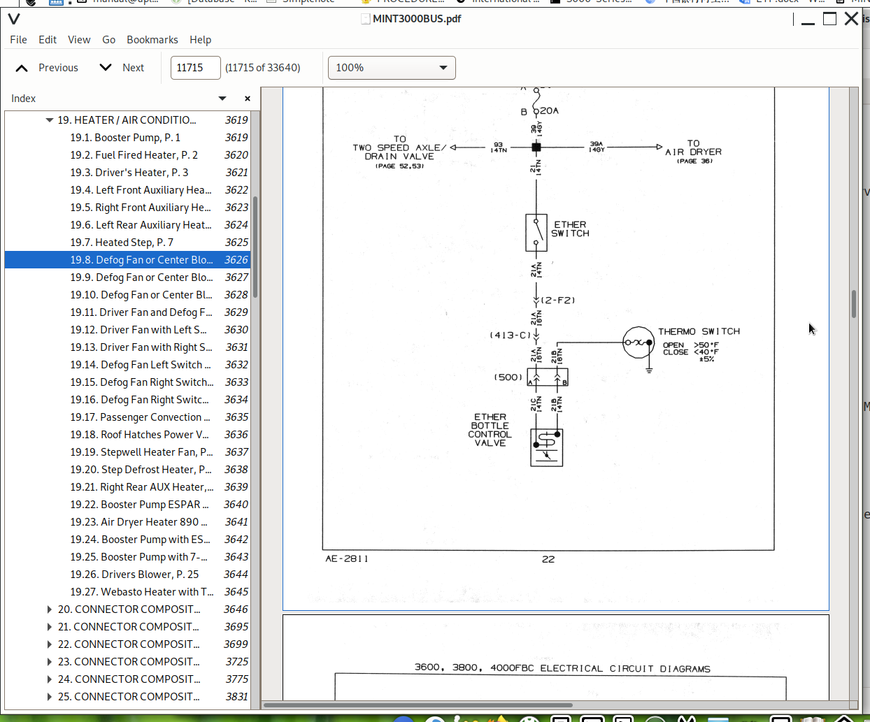
19.8. Defog Fan or Center Blower with Left Switch Panel, P. 8...3626
19.9. Defog Fan or Center Blower with Right Switch Panel, P. 9...3627
19.10. Defog Fan or Center Blower with Dual Switches, P. 10...3628
19.11. Driver Fan and Defog Fan or Center Blower with Left Switc...3629
19.12. Driver Fan with Left SW Defog Fan or Center Blower with D...3630
19.13. Driver Fan with Right Switch Defog Fan or Center Blower w...3631
19.14. Defog Fan Left Switch Output, P. 14...3632
19.15. Defog Fan Right Switch Output, P. 15...3633
19.16. Defog Fan Right Switch Output (Cont.), P. 15A...3634
19.17. Passenger Convection Heater, P. 16...3635
19.18. Roof Hatches Power Vent, P. 17...3636
19.19. Stepwell Heater Fan, P. 18...3637
19.20. Step Defrost Heater, P. 19...3638
19.21. Right Rear AUX Heater, P. 20...3639
19.22. Booster Pump ESPAR with 7-Day Timer, P. 21...3640
19.23. Air Dryer Heater 890 MM / 3900 MM, P. 22...3641
19.24. Booster Pump with ESPAR with White Timer, P. 23...3642
19.25. Booster Pump with 7-Day Timer, ESPAR, P. 24...3643
19.26. Drivers Blower, P. 25...3644
19.27. Webasto Heater with Timer, P. 26...3645
20. CONNECTOR COMPOSITE (1 – 2500) (CHAPTER 20)...3646
20.1. Connector Composite (1), P. 1...3646
20.2. Connector Composite (1), P. 2...3647
20.3. Intentionally Left Blank, P. 3...3648
20.4. Connector Composite (1 / 2A), P. 4...3649
20.5. Connector Composite (2F), P. 5...3650
20.6. Connector Composite (2M), P. 6...3651
20.7. Connector Composite (4M / 7M / 8M), P. 7...3652
20.8. Connector Composite (9 / 10 / 11M), P. 8...3653
20.9. Connector Composite (12M / 13M / 20M), P. 9...3654
20.10. Connector Composite (22M / 23M), P. 10...3655
20.11. Connector Composite (24 / 35M / 35X3), P. 11...3656
20.12. Connector Composite (37F / 43M / 50 / 51 / 69), P. 12...3657
20.13. Connector Composite (74M / 75M / 78M / 79M), P. 13...3658
20.14. Connector Composite (162 / 165 / 168 / 168A), P. 14...3659
20.15. Connector Composite (211M / 212M / 226F / 288X1), P. 15...3660
20.16. Connector Composite (289 / 290 / 291 / 292), P. 16...3661
20.17. Connector Composite (297 / 299 / 350X2), P. 17...3662
20.18. Connector Composite (351 / 352 / 353), P. 18...3663
20.19. Connector Composite (353 / 354), P. 18A...3664
20.20. Connector Composite (382M / 383M / 383F / 384M / 386A), P...3665
20.21. Connector Composite (391 / 392 / 417), P. 20...3666
20.22. Connector Composite (420A / 420B / 438), P. 21...3667
20.23. Connector Composite (523), P. 22...3668
20.24. Connector Composite (523A / 523B / 524 / 533), P. 22A...3669
20.25. Connector Composite (643 / 644F / 644M / 898), P. 23...3670
20.26. Connector Composite (899 / 922 / 922A), P. 24...3671
20.27. Connector Composite (925 / 926 / 996M / 997 / 998), P. 25...3672
20.28. Connector Composite (1003 / 1004), P. 26...3673
20.29. Connector Composite (1008 / 1023), P. 27...3674
20.30. Connector Composite (1030), P. 28...3675
20.31. Connector Composite (1030), P. 29...3676
20.32. Connector Composite (1030P), P. 29A...3677
20.33. Connector Composite (1031 / 1032 / 1033), P. 30...3678
20.34. Connector Composite (1034 / 1036 / 1037 / 1038), P. 31...3679
20.35. Connector Composite (1040), P. 32...3680
20.36. Connector Composite (1041 / 1042A / 1042B / 1050), P. 33...3681
20.37. Connector Composite (1060A / 1060B / 1061A / 1061B / 1062...3682
20.38. Connector Composite (1062B / 1063A / 1063B / 1065A), P. 3...3683
20.39. Connector Composite (1065B / 1066 / 1100A / 1100B), P. 36...3684
20.40. Connector Composite (1111M / 1135 / 1136), P. 37...3685
20.41. Connector Composite (1137 / 1138 / 1139), P. 38...3686
20.42. Connector Composite (1139A / 1139B / 1140 / 1141), P. 39...3687
20.43. Connector Composite (1142 / 1143A / 1146A / 1146B), P. 40...3688
20.44. Connector Composite (1150 / 1150B / 1151), P. 40A...3689
20.45. Connector Composite (1152 / 1153 / 1205), P. 41...3690
20.46. Connector Composite (1206 / 1272 / 1408 / 1409 / 1410 / 1...3691
20.47. Connector Composite (1412 / 1413 / 1415 / 1416), P. 42A...3692
20.48. Connector Composite (1601M / 1601F / 1707M / 1708 / 1709)...3693
20.49. Connector Composite (1800M / 1850 / 1908 / 1952 / 1952A /...3694
21. CONNECTOR COMPOSITE (2501 – 6000) (CHAPTER 21)...3695
21.1. Connector Composite (3043 / 3114 / 3115 / 3117), P. 1...3695
21.2. Connector Composite (3118 / 3322 / 3344 / 4433), P. 2...3696
21.3. Connector Composite (4800 / 5263F / 5263M), P. 3...3697
21.4. Connector Composite (5432M / 5556M / 5678), P. 4...3698
22. CONNECTOR COMPOSITE (6001 – 9999) (CHAPTER 22)...3699
22.1. Connector Composite (6005M / 6010 / 6011 / 6012), P. 1...3699
22.2. Connector Composite (6020), P. 2...3700
22.3. Connector Composite (6120 / 6200 / 6260), P. 3...3701
22.4. Connector Composite (6261 / 6262 / 6263), P. 4...3702
22.5. Connector Composite (6308 / 6329 / 6330 / 6340), P. 5...3703
22.6. Connector Composite (6341), P. 5A...3704
22.7. Connector Composite (6348F / 6348F / 6348M / 6349M), P. 5B...3705
22.8. Connector Composite (6400 / 6402 / 6665M / 6703 / 6705 / 6...3706
22.9. Connector Composite (7150), P. 7...3707
22.10. Connector Composite (7250 / 7301 / 7302 / 7303), P. 8...3708
22.11. Connector Composite (7302 / 7303 / 7306F), P. 8A...3709
22.12. Connector Composite (7306M / 7307A / 7307B / 7307C / 7307...3710
22.13. Connector Composite (7350), P. 9A...3711
22.14. Connector Composite (7600 / 7601M / 7603 / 7604 / 7607 / ...3712
22.15. Connector Composite (7966 / 7966M), P. 11...3713
22.16. Connector Composite (7980 / 7981 / 7982), P. 11A...3714
22.17. Connector Composite (7983 / 7999M / 8721 / 8888M), P. 12...3715
22.18. Connector Composite (9001 / 9003 / 9151 / 9151A), P. 12A...3716
22.19. Connector Composite (9207 / 9258 / 9259 / 9260 / 9260A), ...3717
22.20. Connector Composite (9263 / 9270 / 9533 / 9534), P. 14...3718
22.21. Connector Composite (9535 / 9536 / 9550), P. 14A...3719
22.22. Connector Composite (9850), P. 15...3720
22.23. Connector Composite (9851), P. 16...3721
22.24. Connector Composite (9875), P. 17...3722
22.25. Connector Composite (9900 / 9901 / 9902 / 9903 / 9904), P...3723
22.26. Connector Composite (9996 / 9999M), P. 19...3724
23. CONNECTOR COMPOSITE (10000 – 10250) (CHAPTER 23)...3725
23.1. Connector Composite (10000), P. 1...3725
23.2. Connector Composite (10000), P. 2...3726
23.3. Connector Composite (10003 / 10003L / 10004), P. 3...3727
23.4. Connector Composite (10009 / 10010), P. 4...3728
23.5. Connector Composite (10011 / 10012), P. 4A...3729
23.6. Connector Composite (10013 / 10014 / 10015 / 10016 / 10017...3730
23.7. Connector Composite (10018 / 10019 / 10020 / 10021 / 10022...3731
23.8. Connector Composite (10024 / 10025A / 10025B / 10025C), P...3732
23.9. Connector Composite (10025D / 10026A / 10026B / 10026C), P...3733
23.10. Connector Composite (10026D / 10027 / 10028 / 10028A / 10...3734
23.11. Connector Composite (10029A / 10030 / 10030A / 10031 / 10...3735
23.12. Connector Composite (10032 / 10033 / 10034 / 10035), P. 1...3736
23.13. Connector Composite (10036 / 10038 / 10039 / 10041 / 1004...3737
23.14. Connector Composite (10046 / 10046A / 10047 / 10048 / 100...3738
23.15. Connector Composite (10050 / 10051 / 10070 / 10072 / 1007...3739
23.16. Connector Composite (10076 / 10077 / 10078 / 10100), P. 1...3740
23.17. Connector Composite (10100A / 10101 / 10102 / 10103 / 101...3741
23.18. Connector Composite (10105 / 10106 / 10107), P. 15...3742
23.19. Connector Composite (10108 / 10109 / 10110), P. 16...3743
23.20. Connector Composite (10112 / 10113), P. 17...3744
23.21. Connector Composite (10114 / 10115 / 10116), P. 18...3745
23.22. Connector Composite (10117 / 10118 / 10119 / 10120 / 1012...3746
23.23. Connector Composite (10122 / 10123 / 10124 / 10125), P. 2...3747
23.24. Connector Composite (10127 / 10127A / 10128 / 10129 / 101...3748
23.25. Connector Composite (10133 / 10135 / 10136 / 10137 / 1013...3749
23.26. Connector Composite (10140 / 10141 / 10142 / 10143 / 1014...3750
23.27. Connector Composite (10147 / 10153 / 10154 / 10155A / 101...3751
23.28. Connector Composite (10160 / 10161 / 10176 / 10181), P. 2...3752
23.29. Connector Composite (10182 / 10200), P. 25A...3753
23.30. Connector Composite (10201 / 10202), P. 26...3754
23.31. Connector Composite (10203), P. 26A...3755
23.32. Connector Composite (10204 / 10207A / 10208), P. 27...3756
23.33. Connector Composite (10209 / 10210), P. 28...3757
23.34. Connector Composite (10211 / 10212 / 10213), P. 29...3758
23.35. Connector Composite (10214D / 10214L / 10215 / 10216 / 10...3759
23.36. Connector Composite (10218 / 10219 / 10220 / 10221 / 1022...3760
23.37. Connector Composite (10225D / 10225L / 10226), P. 32...3761
23.38. Connector Composite (10228 / 10229), P. 33...3762
23.39. Connector Composite (10230A), P. 34...3763
23.40. Connector Composite (10230B / 10231A / 10231B), P. 34A...3764
23.41. Connector Composite (10232A / 10233B), P. 35...3765
23.42. Connector Composite (10233A / 10233B), P. 35A...3766
23.43. Connector Composite (10234A / 10234B / 10235), P. 36...3767
23.44. Connector Composite (10236 / 10237), P. 37...3768
23.45. Connector Composite (10238 / 10239), P. 38...3769
23.46. Connector Composite (10240 / 10241A / 10241B), P. 39...3770
23.47. Connector Composite (10242 / 10243 / 10243B), P. 40...3771
23.48. Connector Composite (10244 / 10244B / 10245), P. 41...3772
23.49. Connector Composite (10245B / 10246 / 10246B), P. 42...3773
23.50. Connector Composite (10247 / 10248 / 10249 / 10250), P. 4...3774
24. CONNECTOR COMPOSITE (10251 – 10500) (CHAPTER 24)...3775
24.1. Connector Composite (10252 / 10253 / 10254), P. 1...3775
24.2. Connector Composite (10255 / 10256 / 10257 / 10259), P. 2...3776
24.3. Connector Composite (10260 / 10261 / 10262 / 10263 / 10264...3777
24.4. Connector Composite (10265 / 10266 / 10267 / 10268 / 10269...3778
24.5. Connector Composite (10270B / 10271 / 10272 / 10273 / 1027...3779
24.6. Connector Composite (10278 / 10279 / 10280 / 10281 / 10282...3780
24.7. Connector Composite (10285 / 10286 / 10287 / 10288 / 10289...3781
24.8. Connector Composite (10291 / 10292 / 10293A / 10293B / 102...3782
24.9. Connector Composite (10301 / 10302 / 10303 / 10304 / 10305...3783
24.10. Connector Composite (10301), P. 10...3784
24.11. Connector Composite (10302), P. 11...3785
24.12. Connector Composite (10303 / 10304), P. 12...3786
24.13. Connector Composite (10305), P. 13...3787
24.14. Connector Composite (10306), P. 14...3788
24.15. Connector Composite (10308), P. 15...3789
24.16. Connector Composite (10309), P. 16...3790
24.17. Connector Composite (10310), P. 17...3791
24.18. Connector Composite (10311), P. 18...3792
24.19. Connector Composite (10314 / 10315 / 10316 / 10317), P. 1...3793
24.20. Connector Composite (10318 / 10319 / 10320 / 10321 / 1032...3794
24.21. Connector Composite (10324 / 10325 / 10326 / 10327), P. 2...3795
24.22. Connector Composite (10328 / 10329), P. 22...3796
24.23. Connector Composite (10330 / 10331 / 10332 / 10333), P. 2...3797
24.24. Connector Composite (10334 / 10335), P. 24...3798
24.25. Connector Composite (10336 / 10337 / 10338 / 10339 / 1034...3799
24.26. Connector Composite (10400), P. 26...3800
24.27. Connector Composite (10400), P. 27...3801
24.28. Connector Composite (10401), P. 28...3802
24.29. Connector Composite (10401), P. 29...3803
24.30. Connector Composite (10405), P. 30...3804
24.31. Connector Composite (10406), P. 31...3805
24.32. Connector Composite (10406), P. 31A...3806
24.33. Connector Composite (10410 / 10411 / 10412 / 10412A), P. ...3807
24.34. Connector Composite (10413 / 10413A / 10414 / 10416 / 104...3808
24.35. Connector Composite (10417 / 10418 / 10419), P. 33...3809
24.36. Connector Composite (10420 / 10421), P. 34...3810
24.37. Connector Composite (10422 / 10423), P. 35...3811
24.38. Connector Composite (10424 / 10425 / 10426 / 10427 / 1042...3812
24.39. Connector Composite (10432 / 10433 / 10434 / 10435 / 1043...3813
24.40. Connector Composite (10439 / 10440 / 10441 / 10442 / 1044...3814
24.41. Connector Composite (10445 / 10446 / 10447 / 10448 / 1044...3815
24.42. Connector Composite (10451 / 10452 / 10453), P. 40...3816
24.43. Connector Composite (10457 / 10458 / 10459), P. 41...3817
24.44. Connector Composite (10460 / 10461 / 10462), P. 41A...3818
24.45. Connector Composite (10463 / 10463A / 10464), P. 42...3819
24.46. Connector Composite (10465 / 10466 / 10467 / 10468), P. 4...3820
24.47. Connector Composite (10468A / 10469 / 10470 / 10471), P. ...3821
24.48. Connector Composite (10472), P. 43A...3822
24.49. Connector Composite (10473 / 10474A / 10474B / 10474C / 1...3823
24.50. Connector Composite (10474F / 10474G / 10474H / 10474J / ...3824
24.51. Connector Composite (10474M / 10474N / 10474P / 10474R), ...3825
24.52. Connector Composite (10475 / 10476 / 10479), P. 44C...3826
24.53. Connector Composite (10482 / 10483 / 10483A / 10484), P. ...3827
24.54. Connector Composite (10484A / 10485 / 10485A / 10486), P...3828
24.55. Connector Composite (10489 / 10489A / 10490 / 10491A), P...3829
24.56. Connector Composite (10491B / 10492), P. 47A...3830
25. CONNECTOR COMPOSITE (10501 – 10750) (CHAPTER 25)...3831
25.1. Connector Composite (10513), P. 1...3831
25.2. Connector Composite (10514 / 10515 / 10516), P. 2...3832
25.3. Connector Composite (10517 / 10518 / 10519), P. 3...3833
25.4. Connector Composite (10700), P. 4...3834
25.5. Connector Composite (10700), P. 5...3835
25.6. Connector Composite (10700), P. 6...3836
25.7. Connector Composite (10700), P. 7...3837
25.8. Connector Composite (10701), P. 8...3838
25.9. Connector Composite (10702), P. 9...3839
25.10. Connector Composite (10703 / 10704), P. 10...3840
25.11. Connector Composite (10705 / 10706), P. 11...3841
25.12. Connector Composite (10709 / 10710 / 10711 / 10712), P. 1...3842
25.13. Connector Composite (10713), P. 13...3843
25.14. Connector Composite (10714), P. 14...3844
25.15. Connector Composite (10715), P. 15...3845
25.16. Connector Composite (10716 / 10717), P. 16...3846
25.17. Connector Composite (10718 / 10719), P. 17...3847
25.18. Connector Composite (10720 / 10721), P. 18...3848
25.19. Connector Composite (10722 / 10723), P. 19...3849
25.20. Connector Composite (10724 / 10725), P. 20...3850
25.21. Connector Composite (10726 / 10727), P. 21...3851
25.22. Connector Composite (10728 / 10729), P. 22...3852
25.23. Connector Composite (10730 / 10731 / 10732 / 10733), P. 2...3853
25.24. Connector Composite (10734 / 10735 / 10736 / 10737), P. 2...3854
25.25. Connector Composite (10738 / 10739 / 10740 / 10741), P. 2...3855
25.26. Connector Composite (10742 / 10743 / 10744), P. 26...3856
25.27. Connector Composite (10745C / 10745D), P. 27...3857
25.28. Connector Composite (10747C / 10747D / 10748C / 10748D), ...3858
25.29. Connector Composite (10749C / 10749D), P. 29...3859
26. CONNECTOR COMPOSITE (10751 – 11000) (CHAPTER 26)...3860
26.1. Intentionally Left Blank, P. 1...3860
26.2. Intentionally Left Blank, P. 2...3861
26.3. Intentionally Left Blank, P. 3...3862
26.4. Connector Composite (10757 / 10757A / 10758 / 10758A / 107...3863
26.5. Connector Composite (10760 / 10760A / 10761 / 10761A), P. ...3864
26.6. Connector Composite (10762 / 10763 / 10763A / 10764), P. 5...3865
26.7. Connector Composite (10765A / 10765B / 10766C / 10766D / 1...3866
26.8. Connector Composite (10768 / 10769C / 10769D / 10769E / 10...3867
26.9. Connector Composite (10769H / 10769J), P. 7A...3868
26.10. Connector Composite (10770C / 10770D / 10770E / 10770F / ...3869
26.11. Connector Composite (10771E / 10771F / 10771G / 10771H / ...3870
26.12. Connector Composite (10772C / 10772D / 10772E / 10772F / ...3871
26.13. Connector Composite (10773C / 10773D / 10773E / 10773F), ...3872
26.14. Connector Composite (10773G / 10773H / 10773J / 10773K), ...3873
26.15. Connector Composite (10773L / 10773M / 10774 / 10774A / 1...3874
26.16. Connector Composite (10774C / 10774D / 10774E / 10774F), ...3875
26.17. Connector Composite (10774G / 10774H / 10774J / 10774K), ...3876
26.18. Connector Composite (10774L / 10774N / 10774P), P. 14A...3877
26.19. Connector Composite (10775C / 10775D / 10778C / 10778D), ...3878
26.20. Connector Composite (10778E / 10778F / 10788H / 10788J), ...3879
26.21. Connector Composite (10780 / 10781), P. 15B...3880
26.22. Connector Composite (10781A / 10784 / 10785 / 10786A / 10...3881
26.23. Connector Composite (10788A / 10788B / 10789), P. 17...3882
26.24. Connector Composite (10795 / 10796A / 10796B / 10807A), P...3883
26.25. Connector Composite (10807B / 10807C / 10807D), P. 18A...3884
26.26. Connector Composite (10831 / 10832 / 10833 / 10833A), P. ...3885
26.27. Connector Composite (10837 / 10838 / 10839C / 10839D), P...3886
26.28. Connector Composite (10848A / 10849A / 10850A / 10851A), ...3887
26.29. Connector Composite (10852A / 10853C / 10853D / 11000), P...3888
26.30. Connector Composite (11000), P. 19...3889
26.31. Connector Composite (11000), P. 20...3890
26.32. Connector Composite (11001 / 11003 / 11004L / 11004R), P...3891
26.33. Connector Composite (11005L / 11005R / 11006L / 11006R), ...3892
26.34. Connector Composite (11007L / 11007R / 11008L / 11008R), ...3893
26.35. Connector Composite (11009L / 11009R), P. 23...3894
26.36. Connector Composite (11010L / 11010R / 11011L), P. 24...3895
26.37. Connector Composite (11011R / 11012 / 11015 / 11016), P. ...3896
26.38. Intentionally Left Blank, P. 26...3897
26.39. Connector Composite (11017 / 11018 / 11019 / 11020), P. 2...3898
26.40. Connector Composite (11021 / 11022 / 11023 / 11024), P. 2...3899
26.41. Connector Composite (11025 / 11025A / 11025B / 11025C), P...3900
26.42. Connector Composite (11025D / 11026 / 11027 / 11028), P. ...3901
26.43. Connector Composite (11029 / 11031 / 11033), P. 30...3902
26.44. Connector Composite (11037 / 11038 / 11044), P. 31...3903
0000003361 - IC Bus BE _ CE Models Radiator _ Cooling System Service Manual...3904
toc...3906
Summary of Changes...3906
1. DESCRIPTION...3912
1.1. Surge Tank (if equipped)...3913
1.2. Deaeration Tank...3913
1.3. Fan Shroud...3913
1.4. Fan Drive...3913
1.5. A/C Condenser...3913
1.6. Radiator / Charge Air Cooler Assembly...3913
1.7. Transmission Oil Cooler...3913
1.8. Fuel Cooler Control Assembly...3913
1.9. Low Temperature Radiator (LTR)...3913
1.10. Low Temperature Radiator (LTR) Thermostat...3914
2. Removal and Installation...3915
2.1. Coolant Drain, Pressure Test, and Fill Procedures...3916
2.1.1. Coolant Drain Procedure (Recommended)...3918
2.1.2. Pressure Test Procedure (Recommended)...3921
2.1.3. Coolant Fill Procedure (Recommended)...3922
2.1.4. Coolant Gravity Drain Procedure...3924
2.1.5. Coolant Fill Procedure (optional) (MaxxForce® 7 and DT Engine)...3925
2.1.6. Coolant Fill Procedure (optional) (Cummins® ISB6.7 Engine)...3929
2.2. Splash Panel...3933
2.2.1. Splash Panel – Removal and Installation...3933
2.3. Surge Tank (if equipped)...3933
2.3.1. Surge Tank (with Cummins® ISB6.7 Engine) – Removal...3933
2.3.2. Surge Tank (with Cummins® ISB6.7 Engine) – Installation...3934
2.4. Deaeration Tank...3935
2.4.1. Deaeration Tank – Removal...3935
2.4.2. Deaeration Tank – Installation...3937
2.5. A/C Condenser...3938
2.5.1. A/C Condenser – Removal...3938
2.5.2. A/C Condenser – Installation...3939
2.6. Fan Belts...3940
2.6.1. Auxiliary A/C Compressor Belt (Cummins® ISB6.7 Engine) – Removal ...3940
2.6.2. Auxiliary A/C Compressor Belt (Cummins® ISB6.7 Engine) – Installation ...3941
2.6.3. Fan Belt with A/C (Cummins® ISB6.7 Engine) – Removal ...3942
2.6.4. Fan Belt with A/C (Cummins® ISB6.7 Engine) – Installation ...3943
2.7. Fan and Fan Drive Assembly...3944
2.7.1. Fan and 12TSY Fan Drive (Borg-Warner SA-805) Viscous Type, Screw On – Removal...3944
2.7.2. Fan and 12TSY Fan Drive (Borg-Warner SA-805) Viscous Type, Screw On – Installation...3945
2.7.3. Fan and 12TTB Fan Drive (Borg-Warner SA-795) Viscous Type, Screw On – Removal...3946
2.7.4. Fan and 12TTB Fan Drive (Borg-Warner SA-795) Viscous Type, Screw On – Installation...3947
2.7.5. Fan Removal – (12THJ and 12THT Horton DA) (optional)...3948
2.7.6. Fan Installation – (12THJ and 12THT Horton DA) (optional)...3949
2.7.7. 12THT Horton (DA) Non-Serviceable Fan Drive with ISB6.7 – Removal...3950
2.7.8. 12THT Horton (DA) Non-Serviceable Fan Drive with ISB6.7 – Installation...3951
2.7.9. 12THJ Fan Drive Horton (DA) with ISB6.7 – Removal...3952
2.7.10. 12THJ Fan Drive Horton (DA) with ISB6.7 - Installation...3953
2.7.11. Fan Removal – 12TJA Warner Electric (FC550) (optional)...3954
2.7.12. Fan Installation – (12TJA Warner Electric FC550) (optional)...3955
2.7.13. 12TJA Fan Drive and Journal Bracket (Warner FC550 Assembly) – Removal...3956
2.7.14. 12TJA Fan Drive and Journal Bracket (Warner FC550 Assembly) (optional) Electronically Controlled and Actuated – Instal...3958
2.7.15. 12THT Horton (DMA) Serviceable Fan Drive – Removal...3959
2.7.16. 12THT Horton DriveMaster Advantage (DMA) Serviceable Fan Drive – Installation...3966
2.7.17. 12THT Pulley Bearing – Removal...3967
2.7.18. 12THT Pulley Bearing – Installation...3967
2.7.19. 12THT Fan Drive Friction Liner– Removal...3968
2.7.20. 12THT Fan Drive Friction Liner – Installation...3972
2.7.21. 12THT Clutch Pack Seal Face– Removal...3973
2.7.22. 12THT Clutch Pack Seal Face – Installation...3973
2.7.23. 12THT Air Cartridge – Removal...3974
2.7.24. 12THT Air Cartridge – Installation...3976
2.7.25. 12TTD Fan Drive Borg–Warner 842B Electronic Viscous Fan Type – Removal...3979
2.7.26. 12TTD Fan Drive Borg–Warner 842B Electronic Viscous Fan Type – Installation...3982
2.7.27. 12TTJ Fan Drive Horton VS217 Electronic Viscous Fan – Removal...3983
2.7.28. 12TTJ Fan Drive Horton VS217 Electronic Viscous Fan – Installation...3989
2.8. Fan Shroud...3990
2.8.1. Fan Shroud – Removal...3990
2.8.2. Fan Shroud – Installation...3990
2.9. Radiator Hose...3991
2.9.1. Heat Shrink Clamp – Removal...3991
2.9.2. Heat Shrink Clamp – Installation...3992
2.9.3. Deaeration Tank Hose (Single Mega Bracket) MaxxForce® 7 Engine – Removal ...3996
2.9.4. Deaeration Tank Hose (Single Mega Bracket) MaxxForce® 7 Engine – Installation ...3997
2.9.5. Deaeration Tank Hose MaxxForce® DT Engine without Interstage Charge Air Cooler (ISCAC) – Removal ...3998
2.9.6. Deaeration Tank Hose (Single Mega Bracket) MaxxForce® DT Engine without Interstage Charge Air Cooler (ISCAC) – Installa...4001
2.9.7. Deaeration Tank Hose (Dual Mega Bracket) MaxxForce® DT Engine with Interstage Charge Air Cooler – Removal ...4002
2.9.8. Deaeration Tank Hose (Dual Mega Bracket) MaxxForce® DT Engine with Interstage Charge Air Cooler (ISCAC) – Installation...4009
2.9.9. Deaeration Tank Hose (Single Mega Bracket) Cummins® ISB6.7 Engine – Removal ...4010
2.9.10. Deaeration Tank Hose (Single Mega Bracket) Cummins® ISB6.7 Engine – Installation...4014
2.9.11. Fuel Cooler Valve (FCV) Hoses MaxxForce® 7 Engine – Removal ...4015
2.9.12. Fuel Cooler Valve (FCV) Hoses MaxxForce® 7 Engine – Installation ...4019
2.9.13. Radiator Hoses DT engine – Removal...4020
2.9.14. Radiator Hoses DT engine – Installation...4021
2.9.15. Radiator Hoses ISB6.7 One Piece – Removal...4022
2.9.16. Radiator Hoses ISB6.7 One Piece – Installation...4024
2.9.17. Radiator Hoses MaxxForce® 7 Engine – Removal...4025
2.9.18. Radiator Hoses MaxxForce® 7 Engine – Installation...4027
2.10. Coolant Package...4028
2.10.1. Coolant Package – Removal...4028
2.10.2. Coolant Package – Installation...4034
2.11. Radiator Core / Charge Air Cooler (CAC) Assembly...4035
2.11.1. Radiator Core / CAC Assembly – Removal ...4035
2.11.2. Radiator Core / CAC Assembly – Installation...4037
2.12. Fuel Cooler Control Radiator Assembly ...4038
2.12.1. Fuel Cooler Control Radiator Assembly – Removal...4038
2.12.2. Fuel Cooler Control Radiator Assembly – Installation...4039
2.13. Fuel Cooler Valve (FCV)...4040
2.13.1. Fuel Cooler Valve (FCV) – Removal...4040
2.13.2. Fuel Cooler Control Valve (FCCV) – Installation...4042
2.14. Low Temperature Radiator (LTR)...4043
2.14.1. Low Temperature Radiator – Removal...4043
2.14.2. Low Temperature Radiator – Installation...4044
2.15. Low Temperature Radiator (LTR) Thermostat...4045
2.15.1. LTR Thermostat – Removal...4045
2.15.2. LTR Thermostat – Installation...4046
2.16. Low Temperature Radiator Hoses...4047
2.16.1. Low Temperature Radiator (LTR) Thermostat Hose – Removal...4047
2.16.2. Low Temperature Radiator (LTR) Thermostat Hose – Installation...4051
3. Inspection Procedures...4052
3.1. Deaeration Tank and Cap Inspection Procedures...4052
3.1.1. Deaeration Tank...4052
3.1.2. Deaeration Tank Cap Vacuum Relief Check...4054
3.2. Fan Drive Pulley and Pulley Groove Inspection Procedures...4055
3.2.1. Pulley Crack Inspection...4055
3.2.2. Pulley Nick Inspection...4056
3.3. 12TTB Fan Drive (Borg-Warner SA-795) Viscous Type Inspection Procedures...4057
3.3.1. Fan Drive Movement...4057
3.4. 12TSY Fan Drive (Borg-Warner SA-805) Viscous Type Inspection Procedures...4058
3.4.1. Fan Drive Movement...4058
3.5. 12TTJ Fan Drive Horton VS217 Inspection Procedures...4059
3.5.1. Fan Drive Movement...4059
3.6. 12THT Horton Drivemaster Advantage Fan Drive Inspection Procedures...4061
3.6.1. Fan Drive Movement...4061
3.6.2. Clutch Pack Face Seal...4063
3.6.3. Cartridge Assembly Seal and Spring...4064
3.6.4. Friction Liner Measurement...4066
3.6.5. Fan Drive Bearing Measurement and Inspection...4067
3.7. 12TTD Borg – Warner 842B Visctronics Inspection Procedure...4068
3.7.1. Fan Drive Movement...4068
3.8. Fuel Cooler Valve (FCV) Inspection Procedure...4069
3.8.1. Fuel Cooler Valve (FCV) Filter Screen – Removal...4069
3.8.2. Fuel Cooler Valve (FCV) Filter Screen – Installation...4070
4. 12TJA Warner FC550 Electric Fan Drive System Diagnostics...4071
4.1. START DIAGNOSTICS HERE: 12TJA Warner FC550 System Operational Checks...4071
Overview...4071
Tools Required...4071
Operational Check – Start Fan Drive Diagnostics Here...4071
4.2. Symptom 1: Fan Always On...4074
4.3. Symptom 2: Fan Always Off...4077
4.4. Symptom 3: Cycles Too Frequently...4079
4.5. Symptom 4: Excessive Noise From Fan Drive...4081
5. 12THT Horton DriveMaster Advantage (DMA) Fan Drive System Diagnostics...4084
5.1. Start Diagnostics here: 12THT Horton DriveMaster Advantage (DMA) System Operational Checks...4084
Overview...4084
Tools Required Preliminary Draft...4084
Operational Checks – Start Fan Drive Diagnostics Here...4084
Visual Air Leak Check...4084
5.2. Symptom 1: Fan Always On...4087
5.3. Symptom 2: Fan Always Off...4105
5.4. Symptom 3: Cycles Too Frequently...4113
5.5. Symptom 4: Excessive Noise From Fan Drive...4115
6. 12TTD Borg-Warner 842B Visctronic Fan Drive System Diagnostics...4118
6.1. Start Diagnostics here: 12TTD Borg-Warner 842B Visctronic Fan Drive...4118
Overview...4118
Tools Required...4118
Operational Checks – Start Fan Drive Diagnostics Here...4118
6.1.1. ...4120
6.2. Symptom 1: Fan Always ON...4120
6.3. Symptom 2: Fan Always OFF...4126
6.4. Symptom 3: Cycles Too Frequently...4144
6.5. Symptom 4: Excessive Noise From Fan Drive...4147
7. 12TTJ Horton Drivemaster VS217 Fan Drive Assembly System Diagnostics...4150
7.1. Start Diagnostics here: 12TTJ Horton Drivemaster VS217 Fan Drive Assembly...4150
Overview...4150
Tools Required...4150
Operational Checks – Start Fan Drive Diagnostics Here...4151
7.1.1. ...4153
7.2. Symptom 1: Fan Always ON...4153
7.3. Symptom 2: Fan Always OFF...4159
7.4. Symptom 3: Fan Drive Cycles Too Frequently...4182
7.5. Symptom 4: Excessive Noise From Fan Drive...4182
8. Abbreviations and Acronyms...4185
9. Terminology...4194
tables...4207
Table 145 Torque Chart...4207
0000003601 - 2011 - 2015 IC Bus BE _ CE Series Electrical Circuit Diagrams (Supersedes S08377)...4209
0000017581 - 3600, 3800, 4000FBC Chassis Built November 1997 through February 1999 Electrical Circuit Diagrams...5050
toc...5052
Table of Contents...5052
INSTRUCTIONS AND CHARTS (Chapter 1)...5058
2.1. Circuit Number Identification and Location Chart, p. 1...5058
2.2. Circuit Number Identification and Location Chart, p. 2...5059
2.3. Circuit Number Identification and Location Chart, p. 3...5060
2.4. Circuit Number Identification and Location Chart, p. 4...5061
2.5. Circuit Number Identification and Location Chart, p. 5...5062
2.6. NAVPAK/ECM I6 Engine Controller Connector Pin Number Identi...5063
2.7. Circuit Diagram Instructions, p. 7...5064
2.8. Circuit Diagram Instructions, p. 8...5065
2.9. Schematic Symbol Chart, p. 9...5066
2.10. Relay Functions, p. 10...5067
2.11. Lamp Bulb Chart, p. 11...5068
2.12. International V8 and I6 ECM Controller Connectors Pin Numb...5069
12 VOLT POWER DISTRIBUTION CIRCUIT DIAGRAMS (Chapter 2)...5070
3.1. Accessory, p. 1...5070
3.2. Battery Feeds, Cab, p. 2...5071
3.3. Battery, p. 3...5072
3.4. 1708 Data Link Chassis, p. 4...5073
3.5. Switch Data Link, p. 5...5074
3.6. Drivetrain 1939 Data Link (Cab), p. 6...5075
3.7. Drivetrain 1939 Data Link (Chassis), p. 7...5076
3.8. Grounds Chassis, p. 8...5077
3.9. Grounds Chassis, p. 9...5078
3.10. Grounds IP, p. 10...5079
3.11. Grounds IP, p. 11...5080
3.12. Ignition Cab, p. 12...5081
3.13. Ignition Cab, p. 13...5082
3.14. Ignition Feeds, Chassis, p. 14...5083
3.15. Start, p. 15...5084
CAB ACCESSORIES (Chapter 3)...5085
4.1. Cigar Lighter and Power Feeds, p. 1...5085
4.2. CB Power, p. 2...5086
4.3. Compass and Temperature Display, p. 3...5087
4.4. Front Doors Windows and Locks (Power), p. 4...5088
4.5. Crew Doors Windows and Locks (Power), p. 5...5089
4.6. Horn, Dual Electric, p. 6...5090
4.7. Mirrors (Heated, Lighted and Power), p. 7...5091
4.8. Radio (Entertainment), Speakers, p. 8...5092
4.9. Windshield Wiper and Washer Pump, p. 9...5093
4.10. 2–Way Radio, p. 10...5094
4.11. Switch Pack, Optional Gauge Pack, p. 11...5095
4.12. Lighted Air Shield, p. 12...5096
4.13. Roof Aux. Load, p. 13...5097
4.14. Satellite Communication Qualcomm-MCT and IMCT Systems, p. ...5098
4.15. Self Contained Air Seat, p. 15...5099
4.16. Digital Clock PTC, p. 16...5100
4.17. Transmission Allison LCT Column Shifter, p. 17...5101
4.18. Heated Seats for 7700 Models Only, p. 18...5102
4.19. Backup Camera, p. 19...5103
4.20. XATA Computer, p. 20...5104
4.21. Keyless Ignition System, p. 21...5105
12V CHARGING + CRANKING SYSTEM (Chapter 4)...5106
5.1. I6 EGR Engines, p. 1...5106
5.2. V8 AVNT Engines, p. 2...5107
5.3. Caterpillar, Cummins ISM Engines, p. 3...5108
5.4. I6 HEUI Engines, p. 4...5109
5.5. Caterpillar Engines, Cummins ISM and with Eaton Ultrashift/...5110
5.6. I6 EGR Engines with Air Start, p. 6...5111
FANS AND ENGINE ACCESSORIES (Chapter 5)...5112
6.1. Fan Wiring, p. 1...5112
6.2. Ether Start, p. 2...5113
6.3. Snow Valve, p. 3...5114
6.4. Fan Wiring, Caterpillar and Cummins, p. 4...5115
ELECTRONIC ENGINES (Chapter 6)...5116
7.1. Electronic Engine Controls, I6–EGR Engines, p. 1...5116
7.2. Electronic Engine Controls, I6-EGR Engine Cruise Control an...5117
7.3. Electronic Engine Controls, (V8–AVNT) Engines, p. 3...5118
7.4. Electronic Engine Controls, V8–AVNT Engine Cruise Control a...5119
7.5. Caterpillar C10, C11, C12, and C13 Engines, p. 5...5120
7.6. Cummins ISM Engine, p. 6...5121
7.7. I6 HEUI Engine, p. 7...5122
7.8. I6 HEUI Engine Cruise Control and Body Builder Connections ...5123
GAUGES WITH AND WITHOUT INTEGRAL WARNING LIGHT (Chapter 7)...5124
8.1. IP/Gauge List, p. 1...5124
8.2. Warning Light List, p. 2...5125
8.3. Warning Lights Controlled by Engine, Transmission, ABS Cont...5126
8.4. Engine Oil Pressure and Temp, Speedometer, Tach, Voltmeter ...5127
8.5. IP/Gauges and Warning Lights — Gauge Cluster, p. 5...5128
8.6. Air Pressure Input Circuit, p. 6...5129
8.7. Axle Temperature, FWD Rear and Rear Axles, Gauge Input Circ...5130
8.8. Fuel Gauge Input Circuit (Single Tank) Differential Lock Wa...5131
8.9. Gauges and Warning Lights — Fuel Filter Restriction and Wat...5132
8.10. Gauges and Warning Lights — Park Brake Light and Transmiss...5133
8.11. Gauges and Warning Lights — Ammeter, p. 11...5134
8.12. Engine Oil Temperature Gauge With Caterpillar, p. 12...5135
8.13. Front Axle Engagement Lamp, p. 13...5136
LIGHTS (Chapter 8)...5137
9.1. Back Up Lights, p. 1...5137
9.2. Light Systems — Clearance, Marker, Park, Tail, Turn and Sto...5138
9.3. Light Systems — Clearance, Marker, Park, Tail, Turn and Sto...5139
9.4. Light Systems — Turn Signal and Stop Switches, p. 4...5140
9.5. Dome Light, Map Light, p. 5...5141
9.6. Dome Light, Map Light (Cont.), p. 6...5142
9.7. Fog Light and Work Light, p. 7...5143
9.8. Headlights, p. 8...5144
9.9. Aux. Headlights, Aux. Park, Aux. Turn, p. 9...5145
9.10. Panel Lights, p. 10...5146
CHASSIS ACCESSORIES (Chapter 9)...5147
10.1. Air Dryer and Heated Drain Valve, p. 1...5147
10.2. Antilock Brake System (ABS), Air, p. 2...5148
10.3. Antilock Brake System (ABS), Air, Traction Control, p. 3...5149
10.4. Antilock Brake System (ABS), Hydraulic, p. 4...5150
10.5. Antilock Brake System (ABS), Hydraulic (Cont.), p. 5...5151
10.6. Antilock Brake System (ABS), Hydraulic (Cont.), p. 6...5152
10.7. Two Speed Axle Switch With Manual Transmission and I6 HEUI...5153
10.8. Brake System, Hydraulic, p. 8...5154
10.9. Fuel Transfer Pump, p. 9...5155
10.10. Back of Cab Body Builder and Trailer Stop, Tail, Marker, ...5156
10.11. Body Builder and Trailer Turns, Center Pin ABS, Center Pi...5157
10.12. Body Builder and Trailer Socket Back of Cab Sockets, p. 1...5158
10.13. Body Builder and Trailer Socket End of Frame (EOF) Socket...5159
10.14. Air Solenoid 4–Way Pack, p. 14...5160
10.15. Remote Power Units, Solenoid Packs, Remote Engine Speed C...5161
10.16. HYD Power Park, p. 16...5162
10.17. Air Suspension, p. 17...5163
10.18. Aux. Trailer, Acc Controlled, p. 18...5164
10.19. Aux. Trailer, Battery Controlled, p. 19...5165
10.20. Lift Axles (Non-Steerable), p. 20...5166
10.21. Lift Axles (Steerable), p. 21...5167
10.22. Air Actuated Park Brake, p. 22...5168
10.23. Antilock Brake System, WABCO Air, p. 23...5169
10.24. Antilock Brake System, WABCO Air, p. 24...5170
10.25. Lift Axles, With Non-Steerable for SS Models, p. 25...5171
10.26. Fuel / Water Separator With 12VDC Fuel Preheater, p. 26...5172
10.27. Electronic Trailer Brake Accommodation, p. 27...5173
10.28. Lectrashift Accommodation, p. 28...5174
10.29. Auxiliary 40 Amp Circuit, p. 29...5175
10.30. Hourmeter, Customer Mounted PTO, p. 30...5176
10.31. Remote Start/ Stop, p. 31...5177
10.32. Lift Axle with 14RAR, p. 32...5178
10.33. Lift Gate, p. 33...5179
10.34. Lift Axle Multiplex, p. 34...5180
TRANSMISSIONS (Chapter 10)...5181
11.1. Allison LCT Transmission or Allison 1000, 2000, 2400, p. 1...5181
11.2. Allison MD Transmission, p. 2...5182
11.3. Allison MD Transmission (WTEC), p. 3...5183
11.4. Allison MD Transmission (Cont.), p. 4...5184
11.5. Transmission, WTEC MD W/Auto Neutral, p. 5...5185
11.6. Eaton Autoshift Transmission, p. 6...5186
11.7. Eaton Autoshift Transmission (Cont.), p. 7...5187
11.8. Eaton Lightning Transmission, p. 8...5188
11.9. Allison HD Transmission, p. 9...5189
11.10. Allison HD Transmission, p. 10...5190
11.11. Allison HD Transmission, p. 11...5191
11.12. Allison HD Transmission With Auto Neutral, p. 12...5192
11.13. Allison HD Transmission With Auto Neutral and with 0013WU...5193
11.14. Allison LCT Transmission (Allison 1000, 2000, 2400) with ...5194
11.15. Transmission Retarder Control Wiring with MD Xmsn, Hard W...5195
11.16. Transmission Retarder Control Wiring with MD Xmsn, Hard W...5196
AIR CONDITIONING (Chapter 11)...5197
12.1. HVAC Systems, p. 1...5197
12.2. Air Conditioning (Only), p. 2...5198
12.3. Autotherm Systems, p. 3...5199
CONNECTOR COMPOSITES (Chapter 12)...5200
13.1. Connector Composites (10M), (71), (72), (345F), p. 1...5200
13.2. Connector Composites (420F), (420M), (520), (521), (522), ...5201
13.3. Connector Composites (1002), (1003), (1010), p. 3...5202
13.4. Connector Composite (1011), p. 4...5203
13.5. Connector Composite (1012), p. 5...5204
13.6. Connector Composite (1013), p. 6...5205
13.7. Connector Composite (1014), p. 7...5206
13.8. Connector Composites (1018), (1019M), (1020M), (1021M), (1...5207
13.9. Connector Composites (1027M, F), (1100), (1101A), (1101), ...5208
13.10. Connector Composites (1104), (1106), (1200), (1210), p. 1...5209
13.11. Connector Composites (1300), (1301), (1400), (1402), (141...5210
13.12. Connector Composites (1553), (1554F), (1555), (1600), (16...5211
13.13. Connector Composites (1652), (1657M), (1658), (1659), (18...5212
13.14. Connector Composites (1804), (1807), (1808), (1809), (181...5213
13.15. Connector Composites (1820), (1822), (1823), (1824), (182...5214
13.16. Connector Composites (1918), (1935), (1920), (2000), (200...5215
13.17. Connector Composites (2006M), (2007F), (2021F), (2021M), ...5216
13.18. Connector Composites (2304M), (2305M), (2306M), (2307F), ...5217
13.19. Connector Composites (2601M, F), (2602M, F), (3000M), (30...5218
13.20. Connector Composites (3204M, F), (3209), (3210M), (3211M)...5219
13.21. Connector Composite (4001), p. 21...5220
13.22. Connector Composite (4002), p. 22...5221
13.23. Connector Composite (4003), p. 23...5222
13.24. Connector Composites (4004), (4007), (4008), p. 24...5223
13.25. Connector Composite (4014), p. 25...5224
13.26. Connector Composite (4014/1700), p. 26...5225
13.27. Connector Composites (4015), (4017), (4018), (4019), (402...5226
13.28. Connector Composites (4024), (4030), (4031), (4032), (403...5227
13.29. Connector Composites (4070), (4071), (4087), (4098), (410...5228
13.30. Connector Composite (4103), p. 30...5229
13.31. Connector Composites (4105), (4111), (4120), (4301), p. 3...5230
13.32. Connector Composites (4305), (4410), (4410B), (4410C), (4...5231
13.33. Connector Composites (4411A), (4411B), (4412), (4415), (4...5232
13.34. Connector Composite (4705), p. 34...5233
13.35. Connector Composites (4810), (4712F), (4820), (4713F), (4...5234
13.36. Connector Composites (4900), (4910), (4950), (4951), p. 3...5235
13.37. Connector Composites (6007), (6011), p. 37...5236
13.38. Connector Composites (6013M), (6014), p. 38...5237
13.39. Connector Composites (6015), (6020), (6021), p. 39...5238
13.40. Connector Composites (6200), (6316), (6323), (6332), (633...5239
13.41. Connector Composites (6550), (6703), (6704), (6708), (710...5240
13.42. Connector Composites (7200), (7202), (7203), p. 42...5241
13.43. Connector Composites (7204), (7205), (7206), (7211), (72...5242
13.44. Connector Composites (7214), (7300), (7301), p. 44...5243
13.45. Connector Composites (7302), (7304), (7305), (7306), (750...5244
13.46. Connector Composites (7603), (7604), (7605), (7606), (760...5245
13.47. Connector Composites (7800), (7801M), (7803), (7900), (79...5246
13.48. Connector Composites (7905), (7906), (8000), (8001), (810...5247
13.49. Connector Composites (8201), (8301), (8310), (8311), (831...5248
13.50. Connector Composites (8503), (8503A), (8505), (8506), (85...5249
13.51. Connector Composites (8700), (8701), (8800), (8801), (880...5250
13.52. Connector Composites (9001), (9002), (9100), (9101), (910...5251
13.53. Connector Composites (9260), (9261), (9262), (9263), (926...5252
13.54. Connector Composites (9405), (9501), (9502), (9503), (950...5253
13.55. Connector Composites (9507), (9508), (9509), (9510), (951...5254
13.56. Connector Composites (9516), (9517), (9518), (9519), p. 5...5255
13.57. Connector Composite (9700), p. 57...5256
13.58. Connector Composite (9700), p. 58...5257
13.59. Connector Composites (9715), (9715A), (9715B), p. 59...5258
13.60. Connector Composites (9716), (9716A), (9716B), p. 60...5259
13.61. Connector Composites (9717A), (9717B), p. 61...5260
13.62. Connector Composites (9718), (9719), (9720), (9733), (973...5261
13.63. Connector Composites (9777), (9778), (9800), p. 63...5262
13.64. Connector Composites (9870), (9871), (9811), (9812), (981...5263
13.65. Connector Composites (9913B), (9914), (4100), (4109), (41...5264
0000019442 - IC Bus RE Series (Built September 2017 and After) Chassis Electrical Circuit Diagrams...5265
0000019443 - IC Bus RE Series (Built September 2017 and After) Body Electrical Circuit Diagrams...5507
0000019822 - FE and SFC Bus Series Euro III & V Circuit Diagram ManualCircuit Diagrams...6154
0000020182 - 2016 - 2019 IC Bus BE _ CE Series Electrical Circuit Diagrams...6291
0000650450 - IC Bus™ Propane Autogas CE Series Radiator _ Cooling SystemService Manual...7294
toc...7296
Table of Contents...7296
1. Description...7298
1.1. Cooling System Component Description...7299
1.1.1. Deaeration Tank ...7299
1.1.2. Fan Shroud ...7299
1.1.3. A/C Condenser ...7299
1.1.4. Transmission Oil Cooler Lines...7299
1.1.5. Heater Core...7299
1.1.6. Radiator ...7299
1.1.7. Fan Drive...7299
1.2. Cooling Package Visual Inspection...7300
2. Cooling Package Cleaning Procedures...7301
2.1. Cleaning Cooling Package...7302
3. Coolant Drain and Pressure Test Procedures...7303
3.1. Coolant Drain and Pressure Test Procedures...7303
3.1.1. Coolant Drain Procedure (Recommended)...7307
3.1.2. Pressure Test (Recommended)...7310
3.1.3. Coolant Fill Procedure (Recommended)...7313
3.1.4. Coolant Gravity Drain Procedure (Optional)...7319
3.1.5. Coolant Gravity-Fill Procedure – (Optional)...7319
4. Removal and Installation...7322
4.1. Splash Panel – Removal...7323
4.2. Splash Panel – Installation...7323
4.3. Power Steering Fluid Reservoir – Removal...7323
4.4. Power Steering Fluid Reservoir – Installation...7324
4.5. Deaeration Tank – Removal...7324
4.6. Deaeration Tank – Installation...7325
4.7. Recirculation Seal – Removal...7326
4.8. Recirculation Seal – Installation...7326
4.9. A/C Condenser – Removal...7326
4.10. A/C Condenser – Installation...7330
4.11. Fan Belts – Removal...7330
4.12. Fan Belts – Installation...7331
4.13. Fan and Fan Drive Assembly – Removal...7332
4.14. Fan and Fan Drive Assembly – Installation...7333
4.15. Fan Drive Pulley – Removal...7333
4.16. Fan Drive Pulley – Installation...7334
4.17. Fan Shroud – Removal...7335
4.18. Fan Shroud – Installation...7335
4.19. Radiator Hose Heat Shrink Clamp – Removal...7335
Heat Shrink Clamp – Removal...7336
4.20. Radiator Hose Heat Shrink Clamp – Installation...7336
4.21. Radiator Hose – Removal...7339
4.22. Radiator Hose – Installation...7340
4.23. Radiator Assembly – Removal...7341
4.24. Radiator Assembly – Installation...7343
4.25. Radiator Core – Removal...7345
4.26. Radiator Core – Installation...7350
5. Inspection Procedures...7351
5.1. Deaeration Tank Inspection Procedure...7351
5.2. Deaeration Tank Cap Vacuum Relief Check...7353
5.3. Fan Drive Pulley Crack Inspection...7354
5.4. Fan Drive Pulley Nick Inspection...7355
5.5. Fan Drive Movement Inspection...7356
6. Torque Table...7357
6.1. Torque Chart...7357
7. Abbreviations and Acronyms...7358
8. Terminology...7359
tables...7357
Table 6 Torque Chart...7357
0000944045 - SFC Bus™ Series Stripped Chassis ISB EPA04 Only Electrical Circuit Diagrams...7361
Untitled...7361
0000975235 - 2017-2020 IC Bus CE Series Technician Manual (Service and Diagnostics), Revision 9...7436
toc...7438
Table of Contents...7438
Safety Terminology...7441
Safety Instructions...7441
Work Area...7441
Safety Equipment...7441
Protective Measures...7441
Vehicle...7442
Engine...7442
Fire Prevention...7442
Batteries...7442
Compressed Air...7442
Tools...7443
Fluids Under Pressure...7443
Fuel...7443
Removal of Tools, Parts, and Equipment...7443
Frame and Bumper...7444
1. Tool Box...7446
2. Tow Hook...7447
Front Axle...7448
1. Front Non-Driving Axle...7450
Non-Driving...7450
Dana Spicer®...7450
Overview...7450
Service Information...7451
Tech Tips...7451
Meritor®...7452
Overview...7452
Service Information...7453
Tech Tips...7453
Navistar® Select...7453
Overview...7453
Service Information...7454
Tech Tips...7454
Wheel Seals...7455
Removal...7455
Overview...7455
Special Tools...7455
Equipment Condition...7455
Removal Procedure...7456
Expected Outcome...7458
Follow-On Procedure...7458
Installation...7459
Overview...7459
Special Tools...7459
Equipment Condition...7459
Installation Procedure...7460
Expected Outcome...7462
Follow-On Procedure...7463
Kingpin...7464
Overview...7464
Removal...7465
Overview...7465
Special Tools...7465
Equipment Conditions...7465
Removal Procedure...7466
Expected Outcome...7467
Follow-On Procedure...7467
Installation...7468
Overview...7468
Special Tools...7468
Torque Specifications...7468
Equipment Conditions...7468
Installation Procedure...7469
Expected Outcome...7470
Follow-On Procedure...7470
Front Suspension...7472
Brakes...7476
1. Air Brakes - Foundation...7478
Service Brakes...7478
Overview...7478
2. Air Brakes - Bendix...7479
ABS / ATC / ESC...7479
Overview...7479
ABS...7482
ATC...7483
ESC...7485
ABS Module...7487
Removal...7487
Installation...7488
Overview...7488
Special Tools...7488
Torque Specifications...7488
Equipment Conditions...7488
Installation Procedure...7489
Follow-On Procedure...7490
Modulator Valve...7491
Removal...7491
Overview...7491
Special Tools...7491
Equipment Conditions...7491
Removal Procedure...7492
Follow-On Procedure...7492
Installation...7493
Overview...7493
Special Tools...7493
Equipment Conditions...7493
Installation Procedure...7494
Follow-On Procedure...7494
Steering Angle Sensor...7495
Removal...7495
Overview...7495
Special Tools...7495
Equipment Conditions...7495
Removal Procedure...7496
Follow-On Procedure...7498
Installation...7499
Overview...7499
Special Tools...7499
Equipment Conditions...7499
Installation Procedure...7500
Follow-On Procedure...7502
Traction Relay Valve...7503
Front Removal...7503
Overview...7503
Special Tools...7503
Equipment Conditions...7503
Removal Procedure...7504
Follow-On Procedure...7504
Front Installation...7505
Overview...7505
Special Tools...7505
Torque Specifications...7505
Equipment Conditions...7505
Installation Procedure...7506
Follow-On Procedure...7506
Rear Removal...7507
Overview...7507
Special Tools...7507
Equipment Conditions...7507
Removal Procedure...7508
Follow-On Procedure...7508
Rear Installation...7509
Overview...7509
Special Tools...7509
Torque Specifications...7509
Equipment Conditions...7509
Installation Procedure...7510
Follow-On Procedure...7510
Wheel Speed Sensor...7511
Removal...7511
Overview...7511
Special Tools...7511
Equipment Conditions...7511
Removal Procedure...7512
Follow-On Procedure...7512
Installation...7513
Overview...7513
Special Tools...7513
Torque Specifications...7513
Equipment Conditions...7513
Installation Procedure...7514
Follow-On Procedure...7514
Yaw Rate Sensor...7516
Removal...7516
Overview...7516
Special Tools...7516
Equipment Conditions...7516
Removal Procedure...7517
Follow-On Procedure...7517
Installation...7518
Overview...7518
Special Tools...7518
Equipment Conditions...7518
Installation Procedure...7519
Follow-On Procedure...7519
3. Hydraulic Brakes - Foundation...7520
Disc Brakes...7520
Overview...7520
Front Brake Caliper...7522
Removal...7522
Overview...7522
Special Tools...7522
Equipment Condition...7522
Procedure...7523
Follow-On Procedure...7527
Installation...7528
Overview...7528
Special Tools...7528
Equipment Condition...7529
Procedure...7529
Follow-On Procedure...7532
Rear Brake Caliper...7533
Removal...7533
Overview...7533
Special Tools...7533
Equipment Condition...7533
Procedure...7534
Follow-On Procedure...7538
Installation...7539
Overview...7539
Special Tools...7539
Equipment Condition...7540
Procedure...7540
Follow-On Procedure...7543
Park Brakes...7544
Parking Brake Interlock...7544
Park Brake Cable...7545
Park Brake Cable Adjustment...7547
Overview...7547
Special Tools...7547
Equipment Conditions...7547
Adjustment Procedure...7547
Follow-On Procedure...7550
Park Brake System Inspection...7551
Overview...7551
Special Tools...7551
Equipment Conditions...7551
Inspection Procedure...7551
Follow-On Procedure...7554
Park Brake Shoe Adjustment...7555
Overview...7555
Special Tools...7555
Equipment Conditions...7555
Adjustment Procedure (Drum OFF)...7555
Adjustment Procedure (Drum ON)...7557
Follow-On Procedure...7557
4. Hydraulic Brakes - Wabco...7558
SmartTrac ABS / ATC / ESC with Hydro-Max...7558
Overview...7558
ABS...7559
ATC...7560
ESC...7562
ABS Unit...7564
Removal...7564
Overview...7564
Special Tools...7564
Equipment Conditions...7564
Procedure...7565
Follow-On Procedure...7568
Installation...7569
Overview...7569
Special Tools...7569
Equipment Conditions...7569
Procedure...7570
Follow-On Procedure...7573
Steering Angle Sensor...7574
Removal...7574
Overview...7574
Special Tools...7574
Equipment Conditions...7574
Procedure...7575
Follow-On Procedure...7577
Installation...7578
Overview...7578
Special Tools...7578
Equipment Conditions...7578
Procedure...7579
Follow-On Procedure...7581
Calibration...7582
Overview...7582
Special Tools...7582
Equipment Conditions...7582
Procedure...7583
Follow-On Procedure...7586
Wheel Speed Sensor...7587
Removal...7587
Overview...7587
Special Tools...7587
Equipment Conditions...7587
Procedure...7588
Follow-On Procedure...7588
Installation...7589
Overview...7589
Special Tools...7589
Torque Specifications...7589
Equipment Conditions...7589
Procedure...7590
Follow-On Procedure...7590
Yaw Rate Sensor...7591
Removal...7591
Overview...7591
Special Tools...7591
Equipment Conditions...7591
Procedure...7592
Follow-On Procedure...7592
Installation...7593
Overview...7593
Special Tools...7593
Equipment Conditions...7593
Procedure...7594
Follow-On Procedure...7594
Initialization...7595
Overview...7595
Special Tools...7595
Equipment Conditions...7595
Procedure...7596
Follow-On Procedure...7599
Brake Bleeding...7600
Overview...7600
Special Tools...7600
Equipment Conditions...7600
Procedure...7600
Follow-On Procedure...7601
Manual Brake Bleeding...7602
Overview...7602
Special Tools...7602
Equipment Conditions...7602
Procedure...7603
Follow-On Procedure...7604
Steering...7606
1. Power Steering...7608
Power Steering Gear with Hydro-Max® Brake System...7608
Overview...7608
Cummins B6.7 with TRW...7609
Cummins B6.7 with Sheppard...7609
N9 with TRW...7609
Power Steering Fluid Flow Test...7610
Overview...7610
Special Tools...7610
Equipment Conditions...7610
Procedure...7611
Follow-On Procedure...7612
Drivelines...7614
Exhaust...7618
1. Aftertreatment...7620
Aftertreatment Reuse Guidelines...7620
Overview...7620
DOC, DPF and SCR Housing Reuse Guidelines...7620
DPF Media Types...7620
DOC Inspection and Reuse Guidelines...7621
Overview...7621
Special Tools...7621
Equipment Condition...7621
Inspection Procedure...7622
Reuse Guidelines...7623
DOC Inlet New...7623
DOC Inlet / Outlet - Melted...7624
DOC Inlet - Face Plugged...7625
DOC Inlet / Outlet Face Gouged...7626
Expected Outcome...7626
Follow-On Procedure...7627
DPF Inspection and Reuse Guidelines...7628
Overview...7628
Special Tools...7628
Equipment Condition...7628
Inspection Procedure...7629
Reuse Guidelines...7630
DPF Inlet - New...7630
DPF Inlet - Dirty and Useable...7631
DPF Inlet - Dirty and Useable 2...7633
DPF Inlet - Clean...7634
DPF Inlet - Gouged...7635
DPF Inlet - Ash...7636
DPF Inlet - Dark Soot Rings...7637
DPF Outlet - Soot Stains...7638
DPF Outlet - Burn Marks from Welding...7639
DPF Outlet - Excessive Soot Stains...7640
DPF Outlet - Face Cracked...7641
DPF Outlet - Coolant Staining...7642
DPF Outlet - Melted...7643
Expected Outcome...7643
Follow-On Procedure...7643
SCR Catalyst Inspection and Reuse Guidelines...7644
Overview...7644
Special Tools...7644
Equipment Condition...7644
Inspection Procedure...7645
Reuse Guidelines...7646
New Aftertreatment SCR...7646
Iron Deposits on SCR Inlet...7647
DEF Deposits on SCR Inlet...7648
Media Erosion on SCR Inlet...7649
Water Stains on SCR Inlet...7650
Expected Outcome...7650
Follow-On Procedure...7650
Single Can Indexing...7651
Overview...7651
Special Tools...7651
Equipment Condition...7651
Procedure...7651
Follow-On Procedure...7652
2. Exhaust System...7653
Exhaust System...7653
Overview...7653
Catalytic Converter...7655
Removal...7655
Overview...7655
Special Tools...7655
Equipment Condition...7655
Removal Procedure...7656
Expected Outcome...7658
Follow-On Procedure...7658
Installation...7659
Overview...7659
Special Tools...7659
Equipment Condition...7659
Installation Procedure...7660
Follow-On Procedure...7662
Muffler...7663
Removal...7663
Overview...7663
Special Tools...7663
Equipment Condition...7663
Removal Procedure...7664
Follow-On Procedure...7664
Installation...7665
Overview...7665
Special Tools...7665
Equipment Condition...7665
Installation Procedure...7666
Follow-On Procedure...7666
Oxygen Sensor...7667
Removal...7667
Overview...7667
Special Tools...7667
Equipment Condition...7667
Removal Procedure...7668
Follow-On Procedure...7668
Installation...7669
Overview...7669
Special Tools...7669
Torque Specifications...7669
Equipment Condition...7669
Installation Procedure...7670
Follow-On Procedure...7670
Long Horizontal Tail Pipe...7671
Overview...7671
Single Can Aftertreatment...7672
Overview...7672
Electrical / Software...7674
1. Diagnostic Trouble Code (DTC) List...7680
2. Electronic Service Tools (EST)...7685
Diamond Logic® Builder...7685
Overview...7685
Selecting an Interface Cable...7687
Overview...7687
Special Tools...7687
Equipment Conditions...7687
Selection Procedure...7687
Follow-On Procedure...7688
Connecting to a Vehicle...7689
Overview...7689
Special Tools...7689
Equipment Conditions...7689
Connection Procedure...7689
Follow-On Procedure...7690
Activating Diagnostic Mode...7691
Overview...7691
Special Tools...7691
Equipment Conditions...7691
Activation Procedure...7691
Follow-On Procedure...7692
Starting a Session...7693
Overview...7693
Special Tools...7693
Equipment Conditions...7693
Starting Procedure...7693
Follow-On Procedure...7694
Viewing Fault Codes...7695
Overview...7695
Special Tools...7695
Equipment Conditions...7695
Viewing Procedure...7695
Follow-On Procedure...7695
Clearing Fault Codes...7696
Overview...7696
Special Tools...7696
Equipment Conditions...7696
Clearing Procedure...7696
Follow-On Procedure...7696
Modifying Signals Tab...7697
Overview...7697
Special Tools...7697
Equipment Conditions...7697
Modify Watched Signal Columns...7697
Modify Watched Signals...7698
Follow-On Procedure...7698
Programming Modules...7699
Overview...7699
Special Tools...7699
Equipment Conditions...7699
Programming Procedure...7700
Follow-On Procedure...7703
Input Not Recognized by Body Control Module...7704
Overview...7704
Special Tools...7704
Equipment Conditions...7704
Troubleshooting Procedure...7704
Follow-On Procedure...7705
Output Not Commanded by Body Control Module...7706
Overview...7706
Special Tools...7706
Equipment Conditions...7706
Troubleshooting Procedure...7706
Follow-On Procedure...7707
3. General Electrical Repair...7708
Electrical Connector Cleaning...7708
Overview...7708
Special Tools...7708
Specifications...7708
Equipment Conditions...7708
Cleaning Procedure...7708
Follow-On Procedure...7708
4. 12 Volt System...7709
Battery Box...7709
Overview...7709
Battery Disconnect...7711
Overview...7711
Special Tools...7711
Equipment Conditions...7711
Disconnect Procedure...7711
Follow-On Procedure...7712
Battery Reconnect...7713
Overview...7713
Special Tools...7713
Equipment Conditions...7713
Reconnect Procedure...7714
Follow-On Procedure...7714
Battery Terminal Cleaning...7715
Overview...7715
Special Tools...7715
Equipment Conditions...7715
Cleaning Procedure...7716
Follow-On Procedure...7716
Body Control Module...7717
Diagnostics...7717
Overview...7717
SPN 2003 FMI 9 - Transmission Controller : Abnormal Update Rate...7719
Fault Overview...7719
Associated Faults...7719
Fault Facts...7719
Tools Required...7719
Possible Causes...7719
SPN 2003 FMI 9 - Transmission Controller : Abnormal Update Rate...7721
Fault Overview...7721
Associated Faults...7721
Fault Facts...7721
Tools Required...7721
Possible Causes...7721
SPN 2003 FMI 9 - TCM Data Link Comm. Failure...7723
Fault Overview...7723
Associated Faults...7723
Fault Facts...7723
Tools Required...7723
Possible Causes...7723
Body Control Module Electrical Test...7725
Overview...7725
Special Tools...7725
Equipment Conditions...7725
Test Setup...7725
Charging and Starting System...7730
Electrical System Operational Checkout Procedure...7732
Charging System...7733
Overview...7733
Red Battery Warning Light ON...7737
Overview...7737
Associated Faults...7737
Fault Facts...7737
Special Tools...7737
Possible Causes...7737
Repeated Jump Starts / Parasitic Draw...7739
Overview...7739
Associated Faults...7739
Fault Facts...7739
Special Tools...7739
Possible Causes...7739
Voltmeter Gauge Reading High...7741
Overview...7741
Associated Faults...7741
Fault Facts...7741
Special Tools...7741
Possible Causes...7741
Voltmeter Gauge Reading Low / Fluctuating...7742
Overview...7742
Associated Faults...7742
Fault Facts...7742
Special Tools...7742
Possible Causes...7742
Starting System...7744
Overview...7744
No Click No Crank...7748
Overview...7748
Associated Faults...7748
Fault Facts...7748
Special Tools...7748
Possible Causes...7748
Click No Crank...7750
Overview...7750
Associated Faults...7750
Fault Facts...7750
Special Tools...7750
Possible Causes...7750
Low Cranking Speed...7752
Overview...7752
Associated Faults...7752
Fault Facts...7752
Special Tools...7752
Possible Causes...7752
Charging and Starting Tests...7753
Overview...7753
Individual Battery Test...7754
Overview...7754
Special Tools...7754
Equipment Condition...7754
Test Setup...7754
Test Procedure...7755
Expected Outcome...7757
Follow-On Procedure...7757
Electrical System Test...7758
Overview...7758
Special Tools...7758
Equipment Condition...7759
Test Setup...7759
Battery Pack Test Procedure...7761
Starter System Test Procedure...7764
Charging System Test Procedure...7766
Expected Outcome...7769
Follow-On Procedure...7769
Cable Drop Test...7770
Overview...7770
Special Tools...7770
Equipment Condition...7770
Test Setup...7770
Test Procedure...7770
Expected Outcome...7773
Follow-On Procedure...7773
Parasitic Draw Test...7774
Overview...7774
Special Tools...7774
Equipment Condition...7774
Test Setup...7774
Test Procedure...7774
Expected Outcome...7777
Follow-On Procedure...7777
Manual Engine Bar Test...7778
Overview...7778
Special Tools...7778
Equipment Conditions...7778
Test Setup...7778
Test Procedure...7778
Expected Outcome...7778
Follow-On Procedure...7778
Starter Control Circuit Test...7779
Overview...7779
Special Tools...7779
Equipment Conditions...7779
Test Setup...7779
Test Procedure...7779
Follow-On Procedure...7780
Starter Input Signal Test...7781
Overview...7781
Special Tools...7781
Equipment Conditions...7781
Test Setup...7781
Test Procedure...7781
Follow-On Procedure...7784
Charging and Starting Inspections...7785
Overview...7785
Ring Gear Inspection...7786
Overview...7786
Special Tools...7786
Equipment Conditions...7786
Inspection Procedure...7786
Expected Outcome...7787
Follow-On Procedure...7787
Electrical System Inspection...7788
Overview...7788
Special Tools...7788
Equipment Conditions...7788
Inspection Procedure...7788
Follow-On Procedure...7791
Engine Ramp with Low Battery...7792
Overview...7792
Electrical Grid Control...7793
Starting System Inputs...7796
Crank Inhibit...7796
Key Switch...7798
Neutral Confirmation Allison...7800
Neutral Confirmation...7801
5. Accessories...7802
Adjustable Pedals...7802
Overview...7802
Diagnostics...7806
Operational Checkout Procedure...7807
Overview...7807
Adjustable Pedals Inoperative...7808
Overview...7808
Associated Faults...7808
Fault Facts...7808
Special Tools...7808
Possible Causes...7808
Accelerator Pedal Adjusts And Brake Pedal Does Not...7815
Overview...7815
Associated Faults...7815
Fault Facts...7815
Special Tools...7815
Possible Causes...7815
Brake Pedal Adjusts And Accelerator Pedal Does Not...7816
Overview...7816
Associated Faults...7816
Fault Facts...7816
Special Tools...7816
Possible Causes...7816
SPN 520289 FMI 5 - Adjustable Pedal Motor Control Pin 1 Undercurrent (H-bridge Pin 1)...7817
Fault Overview...7817
Associated Faults...7817
Fault Facts...7817
Special Tools...7817
Possible Causes...7817
SPN 520289 FMI 6 - Adjustable Pedal Motor Control Pin 1 Overcurrent (H-bridge Pin 1)...7821
Fault Overview...7821
Associated Faults...7821
Fault Facts...7821
Special Tools...7821
Possible Causes...7821
SPN 520290 FMI 5 - Adjustable Pedal Motor Control Pin 2 Undercurrent (H-bridge Pin 2)...7825
Fault Overview...7825
Associated Faults...7825
Fault Facts...7825
Special Tools...7825
Possible Causes...7825
SPN 520290 FMI 6 - Adjustable Pedal Motor Control Pin 2 Overcurrent (H-bridge Pin 2)...7829
Fault Overview...7829
Associated Faults...7829
Fault Facts...7829
Special Tools...7829
Possible Causes...7829
SPN 520291 FMI 2 - Adjustable Pedal Switch Error...7833
Fault Overview...7833
Associated Faults...7833
Fault Facts...7833
Special Tools...7833
Possible Causes...7833
Air Drain Valve...7836
Automatic Drain Valve Systems (0595LAN)...7836
Humphrey Drain Valve Systems (0595ALY)...7836
Cruise Control...7838
Steering Wheel Switch...7838
Horns...7839
City (Electric)...7839
Throttle Cruise...7840
6. Aftertreatment...7842
Inhibit Regen...7842
Parked Regen...7842
7. Alarms...7843
Emergency Exit ...7843
Always Hot Override With Exit Buzzer...7843
Exit Buzzer and Warning Light...7844
Post Trip Inspection...7845
To activate the system:...7846
To deactivate the system:...7846
8. Brakes and Traction Control System...7847
Bendix® Air Brake System...7847
Anti-Lock Brake System (ABS)...7847
Overview...7847
Inputs...7850
Outputs...7851
Automatic Traction Control (ATC) System...7853
Overview...7853
Inputs...7855
Outputs...7855
Electronic Stability Control (ESC) System...7857
Overview...7857
Inputs...7859
Outputs...7860
Operational Checkout Procedure...7862
Overview...7862
Special Tools...7862
ABS Module Electrical Test...7863
Overview...7863
Special Tools...7863
Equipment Conditions...7863
Test Setup...7863
Test Procedure...7863
Follow-On Procedure...7865
Wabco Hydraulic Brake System...7866
SmartTrac Anti-Lock Brake System (ABS)...7866
Overview...7866
Operational Checkout Procedure...7873
Overview...7873
Low Brake Fluid Level Diagnostics...7875
Overview...7875
Associated Faults...7875
Fault Facts...7875
Special Tools...7875
Possible Causes...7875
ABS Diagnostics...7878
Overview...7878
Associated Faults...7879
Fault Facts...7879
Special Tools...7879
Possible Causes...7879
SPN 1044 FMI 3 Hydraulic Pump Motor – Above Normal...7887
Overview...7887
Associated Faults...7887
Fault Facts...7887
Special Tools...7887
Possible Causes...7887
SPN 1044 FMI 4 Hydraulic Pump Motor – Below Normal...7891
Overview...7891
Associated Faults...7891
Fault Facts...7891
Special Tools...7891
Possible Causes...7891
SPN 1044 FMI 5 Hydraulic Pump Motor – Open...7897
Overview...7897
Associated Faults...7897
Fault Facts...7897
Special Tools...7897
Possible Causes...7897
SPN 2584 FMI 3 Hydraulic Brake Pressure Warning State Circuit 1 – Above Normal...7903
Overview...7903
Associated Faults...7903
Fault Facts...7903
Special Tools...7903
Possible Causes...7903
SPN 2584 FMI 4 Hydraulic Brake Pressure Warning State Circuit 1 – Below Normal...7910
Overview...7910
Associated Faults...7910
Fault Facts...7910
Special Tools...7910
Possible Causes...7910
SPN 2584 FMI 5 Hydraulic Brake Pressure Warning State Circuit 1 – Open...7918
Overview...7918
Associated Faults...7918
Fault Facts...7918
Special Tools...7918
Possible Causes...7918
SPN 2931 FMI 1 Hydraulic Brake Fluid Level Switch — Below Normal...7925
Overview...7925
Associated Faults...7925
Fault Facts...7925
Possible Causes...7926
SPN 2931 FMI 5 Low Brake Fluid Warning Lamp Malfunction – Open...7927
Overview...7927
Associated Faults...7927
Fault Facts...7927
Special Tools...7927
Possible Causes...7927
SPN 520941 FMI 5 Hydro-Max Control output of BC – Open...7930
Overview...7930
Associated Faults...7930
Fault Facts...7930
Special Tools...7930
Possible Causes...7930
SPN 520941 FMI 6 Hydro-Max Control output of BC – Shorted to Ground / Over Current...7942
Overview...7942
Associated Faults...7942
Fault Facts...7942
Special Tools...7942
Possible Causes...7942
Hydraulic Brake System Inspection...7946
Overview...7946
Special Tools...7946
Equipment Conditions...7946
Test Setup...7946
Test Procedure...7947
Follow-On Procedure...7947
Automatic Traction Control System with SmartTrac...7948
Overview...7948
Electronic Stability Control System with SmartTrac...7951
Overview...7951
Inputs...7952
Outputs...7952
Parking Brake...7953
Overview...7953
Parking Brake Interlock...7955
Park Brake Alarm with Child Pick Up / Drop Off...7955
Park Brake Indicator...7956
Parking Brake Alarm for Park Brake Not Applied...7956
Parking Brake Alarm with Motion Warning System...7956
Operational Checkout Procedure...7960
Overview...7960
Park Brake Switch Diagnostics...7965
Overview...7965
Associated Faults...7965
Fault Facts...7965
Special Tools...7965
Possible Causes...7965
Park Brake Release Interlock Solenoid Diagnostics...7969
Overview...7969
Associated Faults...7969
Fault Facts...7969
Possible Causes...7969
SPN 520980 FMI 5 – Park Brake Release Interlock Solenoid Under Current or Open Circuit...7973
Overview...7973
Associated Faults...7973
Fault Facts...7973
Possible Causes...7973
SPN 520980 FMI 6 – Park Brake Release Interlock Solenoid Over Current...7976
Overview...7976
Associated Faults...7976
Fault Facts...7976
Possible Causes...7976
9. Collision Mitigation Systems...7979
Bendix® Wingman® Advanced™...7979
Overview...7979
Adaptive Cruise Control (ACC)...7980
Alerts...7980
Collision Mitigation Braking...7980
Tech Tips...7982
Operational Checkout Procedure...7983
Overview...7983
Special Tools...7983
Driver Interface Unit...7985
Electrical Test...7985
Overview...7985
Special Tools...7985
Equipment Conditions...7985
Test Setup...7985
Follow-On Procedure...7987
Removal...7988
Overview...7988
Special Tools...7988
Equipment Conditions...7988
Removal Procedure...7988
Follow-On Procedure...7988
Installation...7989
Overview...7989
Special Tools...7989
Torque Specifications...7989
Equipment Conditions...7989
Installation Procedure...7989
Follow-On Procedure...7989
Radar Sensor...7990
Electrical Test...7990
Overview...7990
Special Tools...7990
Equipment Conditions...7990
Test Setup...7990
Follow-On Procedure...7991
Removal...7992
Overview...7992
Special Tools...7992
Equipment Conditions...7992
Removal Procedure...7992
Follow-On Procedure...7993
Installation...7994
Overview...7994
Special Tools...7994
Torque Specifications...7994
Equipment Conditions...7994
Installation Procedure...7994
Follow-On Procedure...7995
Adjustment...7996
Overview...7996
Special Tools...7996
Equipment Conditions...7996
Lateral Adjustment Procedure...7996
Vertical Adjustment Procedure...7998
Follow-On Procedure...8000
Bendix® Wingman® Fusion™...8001
Overview...8001
The following features are included with Bendix Wingman Fusion:...8001
Adaptive Cruise Control (ACC)...8002
Alerts...8002
Collision Mitigation Braking...8003
SafetyDirect Capability...8003
Stationary Vehicle Braking (SVB)...8003
Tech Tips...8005
Operational Checkout Procedure...8006
Overview...8006
Special Tools...8006
Camera Bracket...8009
Removal...8009
Overview...8009
Special Tools...8009
Equipment Conditions...8009
Removal Procedure...8010
Follow-On Procedure...8010
Installation...8011
Overview...8011
Special Tools...8011
Equipment Conditions...8011
Installation Procedure...8012
Follow-On Procedure...8013
Camera Sensor...8014
Electrical Test...8014
Overview...8014
Special Tools...8014
Equipment Conditions...8014
Test Setup...8014
Follow-On Procedure...8016
Removal...8017
Overview...8017
Special Tools...8017
Equipment Conditions...8017
Removal Procedure...8017
Follow-On Procedure...8018
Installation...8019
Overview...8019
Special Tools...8019
Torque Specifications...8019
Equipment Conditions...8019
Installation Procedure...8019
Follow-On Procedure...8020
SafetyDirect® Module...8021
Electrical Test...8021
Overview...8021
Special Tools...8021
Equipment Conditions...8021
Test Setup...8021
Follow-On Procedure...8023
Removal...8024
Overview...8024
Special Tools...8024
Equipment Conditions...8024
Removal Procedure...8024
Follow-On Procedure...8025
Installation...8026
Overview...8026
Special Tools...8026
Torque Specifications...8026
Equipment Conditions...8026
Installation Procedure...8027
Follow-On Procedure...8028
10. Crossing Gate / Power Door...8029
Crossing Gate...8029
Disable Switch Mounted in Panel...8031
Overview...8031
Power Door...8033
Panel Mounted, Steering Wheel Mounted, and Manual Door Input Switch...8034
BCM Input...8035
BCM Output...8036
11. Data Links...8037
CAN Systems...8037
Overview...8037
CAN Faults...8041
Backbone Open...8041
Node Circuit Open...8042
Short...8042
Terminating Resistor Failure...8042
Tech Tips...8042
Operational Checkout Procedure...8044
Overview...8044
Special Tools...8044
500K Powertrain J1939 Diagnostics...8045
Overview...8045
Associated Faults...8046
Fault Facts...8046
Special Tools...8046
Possible Causes...8046
250K Chassis J1939 Diagnostics (Gen4)...8050
Overview...8050
Associated Faults...8051
Fault Facts...8051
Special Tools...8051
Possible Causes...8051
Tests...8055
Overview...8055
CAN Resistance Test...8056
Overview...8056
Special Tools...8056
Equipment Condition...8056
Test Setup...8056
Test Procedure...8056
Follow-On Procedure...8056
CAN Voltage Test...8057
Overview...8057
Special Tools...8057
Equipment Conditions...8057
Test Setup...8057
Test Procedure...8057
Follow-On Procedure...8058
Module Communication Test...8059
Overview...8059
Special Tools...8059
Equipment Condition...8059
Test Setup...8059
Test Procedure...8060
Follow-On Procedure...8060
Power and Ground Test...8061
Overview...8061
Special Tools...8061
Equipment Conditions...8061
Test Setup...8061
Test Procedure...8061
Follow-On Procedure...8062
Power and Ground Voltage Drop Test...8063
Overview...8063
Tools Required...8063
Equipment Condition...8063
Test Setup...8063
Test Procedure...8063
Expected Outcome...8063
Follow-On Procedure...8063
12. Engine - Diesel...8064
Cummins Engine...8064
Overview...8064
Cummins Diagnostics...8066
Table Of Contents...8066
Fault Code Diagnostics...8067
Fault Code List...8067
SPN 111 FMI 1 (Cummins FC 235) - Coolant Level - Data Valid But Below Normal Operating Range - Most Severe Level...8069
Fault Overview...8069
Associated Faults...8069
Fault Facts...8069
Conditions For Clearing The Fault Codes...8069
Possible Causes...8069
SPN 111 FMI 3 (Cummins FC 195) - Coolant Level Sensor 1 Circuit - Voltage Above Normal or Shorted to High Source...8081
Fault Overview...8081
Associated Faults...8081
Fault Facts...8081
Conditions For Clearing The Fault Codes...8081
Possible Causes...8081
SPN 111 FMI 4 (Cummins FC 196) - Coolant Level Sensor 1 Circuit - Voltage Below Normal or Shorted to Low Source...8093
Fault Overview...8093
Associated Faults...8093
Fault Facts...8093
Conditions For Clearing The Fault Codes...8093
Possible Causes...8093
SPN 111 FMI 17 (Cummins FC 2448) - Coolant Level - Data Valid But Below Normal Operating Range - Least Severe Level...8105
Fault Overview...8105
Associated Faults...8105
Fault Facts...8105
Conditions For Clearing The Fault Codes...8105
Possible Causes...8105
SPN 111 FMI 18 (Cummins FC 197) - Coolant Level - Data Valid But Below Normal Operating Range - Moderately Severe Level...8117
Fault Overview...8117
Associated Faults...8117
Fault Facts...8117
Conditions For Clearing The Fault Codes...8117
Possible Causes...8117
SPN 1569 FMI 15 (Cummins FC 6255) - Engine Protection Torque Derate - Data Valid But Above Normal Operating Range - Least Severe Level...8129
Fault Overview...8129
Associated Faults...8129
Fault Facts...8129
Conditions For Clearing The Fault Codes...8129
Possible Causes...8129
SPN 1569 FMI 31 (Cummins FC 3714) - Engine Protection Torque Derate - Condition Exists...8129
Fault Overview...8129
Associated Faults...8129
Fault Facts...8130
Conditions For Clearing The Fault Codes...8130
Possible Causes...8130
SPN 1761 FMI 1 (Cummins FC 1673) - Aftertreatment 1 Diesel Exhaust Fluid Tank Level - Data Valid But Below Normal Operating Range - Most Severe Level...8132
Fault Overview...8132
Associated Faults...8132
Fault Facts...8132
Conditions For Clearing The Fault Codes...8132
Possible Causes...8132
SPN 1761 FMI 3 (Cummins FC 1669) - Aftertreatment 1 Diesel Exhaust Fluid Tank Level Sensor Circuit - Voltage Above Normal or Shorted to High Source...8133
Fault Overview...8133
Associated Faults...8133
Fault Facts...8133
Conditions For Clearing The Fault Codes...8133
Possible Causes...8133
SPN 1761 FMI 4 (Cummins FC 1668) - Aftertreatment 1 Diesel Exhaust Fluid Tank Level Sensor Circuit - Voltage Below Normal or Shorted to Low Source...8134
Fault Overview...8134
Associated Faults...8134
Fault Facts...8134
Conditions For Clearing The Fault Codes...8134
Possible Causes...8134
SPN 1761 FMI 9 (Cummins FC 4677) Aftertreatment 1 Diesel Exhaust Fluid Tank Level - Abnormal Update Rate ...8135
Fault Overview...8135
Associated Faults...8135
Fault Facts...8135
Conditions For Clearing The Fault Codes...8135
Possible Cause...8135
SPN 1761 FMI 10 (Cummins FC 4769) - Aftertreatment 1 Diesel Exhaust Fluid Tank Level Sensor - Abnormal Rate of Change...8140
Fault Overview...8140
Associated Faults...8140
Fault Facts...8140
Conditions For Clearing The Fault Codes...8140
Possible Causes...8140
SPN 1761 FMI 11 (Cummins FC 4739) - Aftertreatment 1 Diesel Exhaust Fluid Tank Level Sensor - Root Cause Not Known...8143
Fault Overview...8143
Associated Faults...8143
Fault Facts...8143
Conditions For Clearing The Fault Codes...8143
SPN 1761 FMI 13 (Cummins FC 4732) - Aftertreatment 1 Diesel Exhaust Fluid Tank Level Sensor - Out of Calibration...8144
Fault Overview...8144
Associated Faults...8144
Fault Facts...8144
Conditions For Clearing The Fault Codes...8144
Possible Causes...8144
SPN 1761 FMI 17 (Cummins FC 3497) - Aftertreatment 1 Diesel Exhaust Fluid Tank Level - Data Valid But Below Normal Operating Range - Least Severe Level...8145
Fault Overview...8145
Associated Faults...8145
Fault Facts...8145
Conditions For Clearing The Fault Codes...8145
Possible Causes...8145
SPN 1761 FMI 18 (Cummins FC 3498) - Aftertreatment 1 Diesel Exhaust Fluid Tank Level - Data Valid But Below Normal Operating Range -Moderately Severe Level ...8146
Fault Overview...8146
Associated Faults...8146
Fault Facts...8146
Conditions For Clearing The Fault Codes...8146
Possible Causes...8146
SPN 3031 FMI 2 (Cummins FC 1679) - Aftertreatment 1 Diesel Exhaust Fluid Tank Temperature - Data Erratic, Intermittent, or Incorrect...8147
Fault Overview...8147
Associated Faults...8147
Fault Facts...8147
Conditions For Clearing The Fault Codes...8147
Possible Causes...8147
SPN 3031 FMI 3 (Cummins FC 1678) - Aftertreatment 1 Diesel Exhaust Fluid Tank Temperature Sensor - Voltage Above Normal or Shorted to High Source ...8149
Fault Overview...8149
Associated Faults...8149
Fault Facts...8149
Conditions For Clearing The Fault Codes...8149
Possible Causes...8149
SPN 3031 FMI 4 (Cummins FC 1677) - Aftertreatment 1 Diesel Exhaust Fluid Tank Temperature Sensor - Voltage Below Normal or Shorted to Low Source...8150
Fault Overview...8150
Associated Faults...8150
Fault Facts...8150
Conditions For Clearing The Fault Codes...8150
Possible Causes...8150
SPN 3031 FMI 9 (Cummins FC 4572) - Aftertreatment 1 Diesel Exhaust Fluid Tank Temperature - Abnormal Update Rate...8151
Fault Overview...8151
Associated Faults...8151
Fault Facts...8151
Conditions For Clearing The Fault Codes...8151
Possible Cause...8151
SPN 3031 FMI 11 (Cummins FC 4737) - Aftertreatment 1 Diesel Exhaust Fluid Tank Temperature - Root Cause Not Known...8156
Fault Overview...8156
Associated Faults...8156
Fault Facts...8156
Conditions For Clearing The Fault Codes...8156
Possible Causes...8156
SPN 3031 FMI 13 (Cummins FC 4731) - Aftertreatment 1 Diesel Exhaust Fluid Tank Temperature Sensor - Out of Calibration...8157
Fault Overview...8157
Associated Faults...8157
Fault Facts...8157
Conditions For Clearing The Fault Codes...8157
Possible Causes...8157
SPN 3364 FMI 2 (Cummins FC 3878) - Aftertreatment Diesel Exhaust Fluid Quality - Data Erratic, Intermittent, or Incorrect...8158
Fault Overview...8158
Associated Faults...8158
Fault Facts...8158
Conditions For Clearing The Fault Codes...8158
Possible Causes...8158
SPN 3364 FMI 3 (Cummins FC 1686) - Aftertreatment Diesel Exhaust Fluid Quality Sensor Circuit - Voltage Above Normal or Shorted to High Source...8159
Fault Overview...8159
Associated Faults...8159
Fault Facts...8159
Conditions For Clearing The Fault Codes...8159
Possible Cause...8159
SPN 3364 FMI 4 - (Cummins 1685) - Aftertreatment Diesel Exhaust Fluid Quality Sensor Circuit - Voltage Below Normal or Shorted to Low Source...8161
Fault Overview...8161
Associated Faults...8161
Fault Facts...8161
Conditions For Clearing The Fault Codes...8161
Possible Cause...8161
SPN 3364 FMI 9 (Cummins FC 3868) - Aftertreatment Diesel Exhaust Fluid Quality - Abnormal Update Rate...8163
Fault Overview...8163
Associated Faults...8163
Fault Facts...8163
Conditions For Clearing The Fault Codes...8163
Possible Cause...8163
SPN 3364 FMI 10 (Cummins FC 4277) - Aftertreatment Diesel Exhaust Fluid Quality - Abnormal Rate of Change ...8168
Fault Overview...8168
Associated Faults...8168
Fault Facts...8168
Conditions For Clearing The Fault Codes...8168
Possible Causes...8168
SPN 3364 FMI 11 (Cummins FC 1715) - Aftertreatment Diesel Exhaust Fluid Quality - Root Cause Not Known...8171
Fault Overview...8171
Associated Faults...8171
Fault Facts...8171
Conditions For Clearing The Fault Codes...8171
Possible Causes...8171
SPN 3364 FMI 13 (Cummins FC 1714) - Aftertreatment Diesel Exhaust Fluid Quality - Out of Calibration...8172
Fault Overview...8172
Associated Faults...8172
Fault Facts...8172
Conditions For Clearing The Fault Codes...8172
Possible Causes...8172
SPN 3364 FMI 15 (Cummins FC 4842) - Aftertreatment Diesel Exhaust Fluid Quality - Data Valid But Above Normal Operating Range - Least Severe Level...8173
Fault Overview...8173
Associated Faults...8173
Fault Facts...8173
Conditions For Clearing The Fault Codes...8173
Possible Causes...8173
SPN 3364 FMI 18 (Cummins FC 3867) - Aftertreatment Diesel Exhaust Fluid Quality - Data Valid But Below Normal Operating Range - Moderately Severe Level...8175
Fault Overview...8175
Associated Faults...8175
Fault Facts...8175
Conditions For Clearing The Fault Codes...8175
Possible Causes...8175
SPN 3521 FMI 11 (Cummins FC 4768) - Aftertreatment 1 Diesel Exhaust Fluid Property - Root Cause Not Known...8177
Fault Overview...8177
Associated Faults...8177
Fault Facts...8177
Conditions For Clearing The Fault Codes...8177
Possible Causes...8177
SPN 3521 FMI 16 (Cummins FC 6765) - Aftertreatment Diesel Exhaust Fluid Property - Data Valid But Above Normal Operating Range - Moderately Severe Level...8178
Fault Overview...8178
Associated Faults...8178
Fault Facts...8178
Conditions For Clearing The Fault Codes...8178
Possible Causes...8178
SPN 3521 FMI 18 (Cummins FC 6766) - Aftertreatment Diesel Exhaust Fluid Property - Data Valid But Below Normal Operating Range - Moderately Severe Level...8180
Fault Overview...8180
Associated Faults...8180
Fault Facts...8180
Conditions For Clearing The Fault Codes...8180
Possible Causes...8180
SPN 3521 FMI 31 (Cummins FC 4235) - Aftertreatment 1 Diesel Exhaust Fluid Property- Condition Exists...8182
Fault Overview...8182
Associated Faults...8182
Fault Facts...8182
Conditions For Clearing The Fault Codes...8182
Possible Causes...8182
SPN 4096 FMI 31 (Cummins FC 3547) - Aftertreatment Diesel Exhaust Fluid Tank Empty - Condition Exists...8184
Fault Overview...8184
Associated Faults...8184
Fault Facts...8184
Conditions For Clearing The Fault Codes...8184
Possible Causes...8184
SPN 5246 FMI 0 (Cummins FC 3712) - Aftertreatment SCR Operator Inducement - Data Valid But Above Normal Operating Range - Most Severe Level...8185
Fault Overview...8185
Associated Faults...8185
Fault Facts...8185
Conditions For Clearing The Fault Codes...8185
Possible Causes...8185
SPN 5246 FMI 15 (Cummins FC 4134) - Aftertreatment SCR Operator Inducement - Data Valid But Above Normal Operating Range - Least Severe Level...8186
Fault Overview...8186
Associated Faults...8186
Fault Facts...8186
Conditions For Clearing The Fault Codes...8186
Possible Causes...8186
SPN 5246 FMI 16 (Cummins FC 6254) - Aftertreatment SCR Operator Inducement - Data Valid But Above Normal Operating Range - Moderately Severe Level...8187
Fault Overview...8187
Associated Faults...8187
Fault Facts...8187
Conditions For Clearing The Fault Codes...8187
Possible Causes...8187
Tests and Inspections...8188
Overview...8188
DEF Head Unit Coolant Line Routing Inspection...8189
Overview...8189
Tools Required...8189
Equipment Condition...8189
Inspection Procedure...8189
Expected Outcome...8190
DEF Quality Test...8191
Overview...8191
Tools Required...8191
Equipment Condition...8191
Test Procedure...8191
Expected Outcome...8192
DEFTHV Coolant Flow Test...8193
Overview...8193
Tools Required...8193
Equipment Condition...8193
Test Setup...8193
Test Procedure...8193
Expected Outcome...8193
13. Engine - Gas...8194
2018 PSI 8.8L Gas Engine...8194
Overview...8194
PSI Gas Engine Diagnostics...8196
Table Of Contents...8196
Fault Code Diagnostics...8197
Diagnostic Trouble Code (DTC) List...8197
SPN 29 FMI 3 - Pedal Position Sensor/Switch "E" Circuit High Input...8201
Fault Overview...8201
Fault Facts...8201
Special Tools...8201
Possible Causes...8201
SPN 29 FMI 4 - Pedal Position Sensor/Switch "E" Circuit Low Input...8205
Overview...8205
Fault Facts...8205
Special Tools...8205
Possible Causes...8205
SPN 91 FMI 2 - Throttle/Pedal Position Sensor/Switch "D" / "E" Voltage Correlation...8209
Overview...8209
Fault Facts...8209
Special Tools...8209
Possible Causes...8209
SPN 91 FMI 3 - Pedal Position Sensor/Switch "D" Circuit High Input...8215
Overview...8215
Fault Facts...8215
Special Tools...8215
Possible Causes...8215
SPN 91 FMI 4 - Pedal Position Sensor/Switch "D" Circuit Low Input...8219
Overview...8219
Fault Facts...8219
Special Tools...8219
Possible Causes...8219
SPN 96 FMI 2 - Fuel Level Sensor "A" Circuit Intermittent...8223
Overview...8223
Fault Facts...8223
Special Tools...8223
Possible Causes...8223
SPN 96 FMI 3 - Fuel Level Sensor “A” Circuit High...8228
Overview...8228
Fault Facts...8228
Special Tools...8228
Possible Causes...8228
SPN 96 FMI 4 - Fuel Level Sensor “A” Circuit Low...8233
Overview...8233
Fault Facts...8233
Special Tools...8233
Possible Causes...8233
SPN 96 FMI 7 - Fuel Level Sensor “A” Circuit Range/Performance...8238
Overview...8238
Fault Facts...8238
Special Tools...8238
Possible Causes...8238
SPN 132 FMI 0 - Mass Air Flow Circuit High Input...8243
Overview...8243
Fault Facts...8243
Special Tools...8243
Possible Causes...8243
SPN 132 FMI 1- Mass Air Flow Circuit Low Input...8252
Overview...8252
Fault Facts...8252
Special Tools...8252
Possible Causes...8252
SPN 132 FMI 2- Mass Air Flow Circuit Range/Performance...8261
Overview...8261
Fault Facts...8261
Special Tools...8261
Possible Causes...8261
SPN 168 FMI 0 – System Voltage High...8270
Overview...8270
Fault Facts...8270
Special Tools...8270
Possible Causes...8270
SPN 168 FMI 1 - System Voltage Low...8273
Overview...8273
Fault Facts...8273
Special Tools...8273
Possible Causes...8273
SPN 191 FMI 5 - Vehicle Speed Sensor “A” Circuit No Signal...8278
Overview...8278
Fault Facts...8278
Special Tools...8278
Possible Causes...8278
SPN 629 FMI 14 - ECM/PCM Processor – Analog to Digital APP Input Correlation...8284
Overview...8284
Fault Facts...8284
Special Tools...8284
Possible Causes...8284
SPN 639 FMI 5 - High Speed CAN Communication Bus...8290
Fault Overview...8290
Fault Facts...8290
Special Tools...8290
Possible Causes...8290
SPN 639 FMI 8 - Vehicle Communication Bus A Performance...8292
Fault Overview...8292
Fault Facts...8292
Special Tools...8292
Possible Causes...8292
SPN 651 FMI 3 - Cylinder 1 Injector Circuit High...8294
Overview...8294
Fault Facts...8294
Special Tools...8294
Possible Causes...8294
SPN 651 FMI 4 - Cylinder 1 Injector Circuit Low...8303
Overview...8303
Fault Facts...8303
Special Tools...8303
Possible Causes...8303
SPN 651 FMI 5 - Injector Circuit/Open - Cylinder 1...8312
Overview...8312
Fault Facts...8312
Special Tools...8312
Possible Causes...8312
SPN 652 FMI 3 - Cylinder 2 Injector Circuit High...8321
Overview...8321
Fault Facts...8321
Special Tools...8321
Possible Causes...8321
SPN 652 FMI 4 - Cylinder 2 Injector Circuit Low...8330
Overview...8330
Fault Facts...8330
Special Tools...8330
Possible Causes...8330
SPN 652 FMI 5 - Injector Circuit/Open - Cylinder 2...8339
Overview...8339
Fault Facts...8339
Special Tools...8339
Possible Causes...8339
SPN 653 FMI 3 - Cylinder 3 Injector Circuit High...8348
Overview...8348
Fault Facts...8348
Special Tools...8348
Possible Causes...8348
SPN 653 FMI 4 - Cylinder 3 Injector Circuit Low...8357
Overview...8357
Fault Facts...8357
Special Tools...8357
Possible Causes...8357
SPN 653 FMI 5 - Injector Circuit/Open - Cylinder 3...8366
Overview...8366
Fault Facts...8366
Special Tools...8366
Possible Causes...8366
SPN 654 FMI 3 - Cylinder 4 Injector Circuit High...8375
Overview...8375
Fault Facts...8375
Special Tools...8375
Possible Causes...8375
SPN 654 FMI 4 - Cylinder 4 Injector Circuit Low...8384
Overview...8384
Fault Facts...8384
Special Tools...8384
Possible Causes...8384
SPN 654 FMI 5 - Injector Circuit/Open - Cylinder 4...8393
Overview...8393
Fault Facts...8393
Special Tools...8393
Possible Causes...8393
SPN 655 FMI 3 - Cylinder 5 Injector Circuit High...8402
Overview...8402
Fault Facts...8402
Special Tools...8402
Possible Causes...8402
SPN 655 FMI 4 - Cylinder 5 Injector Circuit Low...8411
Overview...8411
Fault Facts...8411
Special Tools...8411
Possible Causes...8411
SPN 655 FMI 5 - Injector Circuit/Open - Cylinder 5...8420
Overview...8420
Fault Facts...8420
Special Tools...8420
Possible Causes...8420
SPN 656 FMI 3 - Cylinder 6 Injector Circuit High...8429
Overview...8429
Fault Facts...8429
Special Tools...8429
Possible Causes...8429
SPN 656 FMI 4 - Cylinder 6 Injector Circuit Low...8438
Overview...8438
Fault Facts...8438
Special Tools...8438
Possible Causes...8438
SPN 656 FMI 5 - Injector Circuit/Open - Cylinder 6...8447
Overview...8447
Fault Facts...8447
Special Tools...8447
Possible Causes...8447
SPN 657 FMI 3 - Cylinder 7 Injector Circuit High...8456
Overview...8456
Fault Facts...8456
Special Tools...8456
Possible Causes...8456
SPN 657 FMI 4 - Cylinder 7 Injector Circuit Low...8465
Overview...8465
Fault Facts...8465
Special Tools...8465
Possible Causes...8465
SPN 657 FMI 5 - Injector Circuit/Open - Cylinder 7...8474
Overview...8474
Fault Facts...8474
Special Tools...8474
Possible Causes...8474
SPN 658 FMI 3 - Cylinder 8 Injector Circuit High...8483
Overview...8483
Fault Facts...8483
Special Tools...8483
Possible Causes...8483
SPN 658 FMI 4 - Cylinder 8 Injector Circuit Low...8492
Overview...8492
Fault Facts...8492
Special Tools...8492
Possible Causes...8492
SPN 658 FMI 5 - Injector Circuit/Open - Cylinder 8...8501
Overview...8501
Fault Facts...8501
Special Tools...8501
Possible Causes...8501
SPN 677 FMI 3 - Starter Relay "A" Circuit High...8510
Overview...8510
Fault Facts...8510
Special Tools...8510
Possible Causes...8510
SPN 677 FMI 4 - Starter Relay "A" Circuit Low...8524
Overview...8524
Fault Facts...8524
Special Tools...8524
Possible Causes...8524
SPN 677 FMI 5 - Starter Relay "A" Circuit ...8538
Overview...8538
Fault Facts...8538
Special Tools...8538
Possible Causes...8538
SPN 876 FMI 3 - A/C Clutch Relay Control Circuit High...8552
Fault Overview...8552
Fault Facts...8552
Special Tools...8552
Possible Causes...8552
SPN 876 FMI 4 - A/C Clutch Relay Control Circuit Low...8556
Fault Overview...8556
Fault Facts...8556
Special Tools...8556
Possible Causes...8556
SPN 876 FMI 5 - A/C Clutch Relay Control Circuit Open...8560
Fault Overview...8560
Fault Facts...8560
Special Tools...8560
Possible Causes...8560
SPN 1045 FMI 7 - Brake Switch "A" Circuit...8564
Overview...8564
Fault Facts...8564
Special Tools...8564
Possible Causes...8564
SPN 1268 FMI 3 - Ignition Coil “A” Primary Control Circuit High...8567
Overview...8567
Fault Facts...8567
Special Tools...8567
Possible Causes...8567
SPN 1268 FMI 4 - Ignition Coil “A” Primary Control Circuit Low...8576
Overview...8576
Fault Facts...8576
Special Tools...8576
Possible Causes...8576
SPN 1268 FMI 5 - Ignition Coil “A” Primary Control Circuit Open...8585
Overview...8585
Fault Facts...8585
Special Tools...8585
Possible Causes...8585
SPN 1269 FMI 3 - Ignition Coil "D" Primary Control Circuit High...8594
Overview...8594
Fault Facts...8594
Special Tools...8594
Possible Causes...8594
SPN 1269 FMI 4 - Ignition Coil "D" Primary Control Circuit Low...8603
Overview...8603
Fault Facts...8603
Special Tools...8603
Possible Causes...8603
SPN 1269 FMI 5 - Ignition Coil "D" Primary Control Circuit Open...8612
Overview...8612
Fault Facts...8612
Special Tools...8612
Possible Causes...8612
SPN 1270 FMI 3 - Ignition Coil "H" Primary Control Circuit High...8621
Overview...8621
Fault Facts...8621
Special Tools...8621
Possible Causes...8621
SPN 1270 FMI 4 - Ignition Coil "H" Primary Control Circuit Low...8630
Overview...8630
Fault Facts...8630
Special Tools...8630
Possible Causes...8630
SPN 1270 FMI 5 - Ignition Coil "H" Primary Control Circuit Open...8639
Overview...8639
Fault Facts...8639
Special Tools...8639
Possible Causes...8639
SPN 1271 FMI 3 - Ignition Coil "G" Primary Control Circuit High...8648
Overview...8648
Fault Facts...8648
Special Tools...8648
Possible Causes...8648
SPN 1271 FMI 4 - Ignition Coil "G" Primary Control Circuit Low...8657
Overview...8657
Fault Facts...8657
Special Tools...8657
Possible Causes...8657
SPN 1271 FMI 5 - Ignition Coil "G" Primary Control Circuit Open...8666
Overview...8666
Fault Facts...8666
Special Tools...8666
Possible Causes...8666
SPN 1272 FMI 3 - Ignition Coil "F" Primary Control Circuit High...8675
Overview...8675
Fault Facts...8675
Special Tools...8675
Possible Causes...8675
SPN 1272 FMI 4 - Ignition Coil "F" Primary Control Circuit Low...8684
Overview...8684
Fault Facts...8684
Special Tools...8684
Possible Causes...8684
SPN 1272 FMI 5 - Ignition Coil "F" Primary Control Circuit Open...8693
Overview...8693
Fault Facts...8693
Special Tools...8693
Possible Causes...8693
SPN 1273 FMI 3 - Ignition Coil "E" Primary Control Circuit High...8702
Overview...8702
Fault Facts...8702
Special Tools...8702
Possible Causes...8702
SPN 1273 FMI 4 - Ignition Coil "E" Primary Control Circuit Low...8711
Overview...8711
Fault Facts...8711
Special Tools...8711
Possible Causes...8711
SPN 1273 FMI 5 - Ignition Coil "E" Primary Control Circuit Open...8720
Overview...8720
Fault Facts...8720
Special Tools...8720
Possible Causes...8720
SPN 1274 FMI 3 - Ignition Coil "C" Primary Control Circuit High...8729
Overview...8729
Fault Facts...8729
Special Tools...8729
Possible Causes...8729
SPN 1274 FMI 4 - Ignition Coil "C" Primary Control Circuit Low...8738
Overview...8738
Fault Facts...8738
Special Tools...8738
Possible Causes...8738
SPN 1274 FMI 5 - Ignition Coil "C" Primary Control Circuit Open...8747
Overview...8747
Fault Facts...8747
Special Tools...8747
Possible Causes...8747
SPN 1275 FMI 3 - Ignition Coil "B" Primary Control Circuit High...8756
Overview...8756
Fault Facts...8756
Special Tools...8756
Possible Causes...8756
SPN 1275 FMI 4 - Ignition Coil "B" Primary Control Circuit Low...8765
Overview...8765
Fault Facts...8765
Special Tools...8765
Possible Causes...8765
SPN 1275 FMI 5 - Ignition Coil "B" Primary Control Circuit Open...8774
Overview...8774
Fault Facts...8774
Special Tools...8774
Possible Causes...8774
SPN 1347 FMI 3 - Fuel Pump 1 Circuit Short High...8783
Overview...8783
Fault Facts...8783
Special Tools...8783
Possible Causes...8783
SPN 1347 FMI 4 - Fuel Pump 1 Circuit Short Low...8787
Overview...8787
Fault Facts...8787
Special Tools...8787
Possible Causes...8787
SPN 1347 FMI 5 - Fuel Pump 1 Circuit Open...8791
Overview...8791
Fault Facts...8791
Special Tools...8791
Possible Causes...8791
SPN 1485 FMI 3 - ECM Power Control Circuit High...8795
Overview...8795
Fault Facts...8795
Special Tools...8795
Possible Causes...8795
SPN 1485 FMI 4 - ECM Power Control Circuit Low...8800
Overview...8800
Fault Facts...8800
Special Tools...8800
Possible Causes...8800
SPN 1485 FMI 5 - ECM Power Control Circuit Open...8805
Overview...8805
Fault Facts...8805
Special Tools...8805
Possible Causes...8805
SPN 2003 FMI 8 - Lost Communication with TCM...8810
Fault Overview...8810
Fault Facts...8810
Special Tools...8810
Possible Causes...8810
SPN 2003 FMI 19 - Invalid Data Received From TCM...8812
Fault Overview...8812
Fault Facts...8812
Special Tools...8812
Possible Causes...8812
SPN 2007 FMI 8 - Lost Communication with PTO Control Module...8814
Fault Overview...8814
Fault Facts...8814
Special Tools...8814
Possible Causes...8814
SPN 2011 FMI 2 - ABS Rough Road Message Rationality...8816
Fault Overview...8816
Fault Facts...8816
Special Tools...8816
Possible Causes...8816
SPN 2011 FMI 19 - Invalid Data Received From Anti-Lock Brake System (ABS) Control Module...8818
Fault Overview...8818
Fault Facts...8818
Special Tools...8818
Possible Causes...8818
SPN 2033 FMI 8 - Lost Communication with Body Control Module...8820
Fault Overview...8820
Fault Facts...8820
Special Tools...8820
Possible Causes...8820
SPN 2609 FMI 3 - A/C Refrigerant Pressure Sensor "A" Circuit High...8822
Overview...8822
Fault Facts...8822
Special Tools...8822
Possible Causes...8822
SPN 2609 FMI 4 - A/C Refrigerant Pressure Sensor "A" Circuit Low...8826
Overview...8826
Fault Facts...8826
Special Tools...8826
Possible Causes...8826
SPN 2634 FMI 15 - System Voltage High - Main Relay...8830
Overview...8830
Fault Facts...8830
Special Tools...8830
Possible Causes...8830
SPN 2634 FMI 17 - System Voltage Low - Main Relay...8833
Overview...8833
Fault Facts...8833
Special Tools...8833
Possible Causes...8833
SPN 3052 FMI 5 - Rough Road Sensor Not Detected...8842
Overview...8842
Fault Facts...8842
Special Tools...8842
Possible Causes...8842
SPN 3053 FMI 1 - EVAP System Leak Detected (Large Leak)...8845
Overview...8845
Associated Faults...8845
Fault Facts...8845
Special Tools...8845
Possible Causes...8845
SPN 3053 FMI 2 - EVAP System Incorrect Purge Flow...8853
Overview...8853
Fault Facts...8853
Special Tools...8853
Possible Causes...8853
SPN 3222 FMI 1 - HO2S Heater Control Circuit Bank 1 Sensor 1...8859
Overview...8859
Fault Facts...8859
Special Tools...8859
Possible Causes...8859
SPN 3222 FMI 3 - Bank 1 Sensor 1 O2S Heater Control Circuit High...8868
Overview...8868
Fault Facts...8868
Special Tools...8868
Possible Causes...8868
SPN 3222 FMI 4 - Bank 1 Sensor 1 O2S Heater Control Circuit Low...8877
Overview...8877
Fault Facts...8877
Special Tools...8877
Possible Causes...8877
SPN 3222 FMI 5 - Bank 1 Sensor 1 O2S Heater Control Circuit Open...8886
Overview...8886
Fault Facts...8886
Special Tools...8886
Possible Causes...8886
SPN 3232 FMI 1 - HO2S Heater Control Circuit Bank 1 Sensor 2...8895
Overview...8895
Fault Facts...8895
Special Tools...8895
Possible Causes...8895
SPN 3232 FMI 3 - Bank 1 Sensor 2 O2S Heater Control Circuit High...8904
Overview...8904
Fault Facts...8904
Special Tools...8904
Possible Causes...8904
SPN 3232 FMI 4 - Bank 1 Sensor 2 O2S Heater Control Circuit Low...8913
Overview...8913
Fault Facts...8913
Special Tools...8913
Possible Causes...8913
SPN 3232 FMI 5 - Bank 1 Sensor 2 O2S Heater Control Circuit Open...8922
Overview...8922
Fault Facts...8922
Special Tools...8922
Possible Causes...8922
SPN 3262 FMI 1 - HO2S Heater Control Circuit Bank 2 Sensor 1...8931
Overview...8931
Fault Facts...8931
Special Tools...8931
Possible Causes...8931
SPN 3262 FMI 3 - Bank 2 Sensor 1 O2S Heater Control Circuit High...8940
Overview...8940
Fault Facts...8940
Special Tools...8940
Possible Causes...8940
SPN 3262 FMI 4 - Bank 2 Sensor 1 O2S Heater Control Circuit Low...8949
Overview...8949
Fault Facts...8949
Special Tools...8949
Possible Causes...8949
SPN 3262 FMI 5 - Bank 2 Sensor 1 O2S Heater Control Circuit Open...8958
Overview...8958
Fault Facts...8958
Special Tools...8958
Possible Causes...8958
SPN 3271 FMI 1 - HO2S Heater Control Circuit Bank 2 Sensor 2...8967
Overview...8967
Fault Facts...8967
Special Tools...8967
Possible Causes...8967
SPN 3272 FMI 3 - Bank 2 Sensor 2 O2S Heater Control Circuit High...8976
Overview...8976
Fault Facts...8976
Special Tools...8976
Possible Causes...8976
SPN 3272 FMI 4 - Bank 2 Sensor 2 O2S Heater Control Circuit Low...8985
Overview...8985
Fault Facts...8985
Special Tools...8985
Possible Causes...8985
SPN 3272 FMI 5 - Bank 2 Sensor 2 O2S Heater Control Circuit Open...8994
Overview...8994
Fault Facts...8994
Special Tools...8994
Possible Causes...8994
SPN 7833 FMI 3 - EVAP System Vent Control Valve Circuit High...9003
Overview...9003
Fault Facts...9003
Special Tools...9003
Possible Causes...9003
SPN 7833 FMI 4 - EVAP System Vent Control Valve Circuit Low...9010
Overview...9010
Fault Facts...9010
Special Tools...9010
Possible Causes...9010
SPN 7833 FMI 5 - EVAP System Vent Control Valve Circuit Open...9017
Overview...9017
Fault Facts...9017
Special Tools...9017
Possible Causes...9017
SPN 7833 FMI 7 - EVAP System Vent Valve Stuck Closed...9024
Overview...9024
Associated Faults...9024
Fault Facts...9024
Special Tools...9024
Possible Causes...9024
SPN 7834 FMI 3 - EVAP System Purge Control Valve Circuit High...9030
Overview...9030
Fault Facts...9030
Special Tools...9030
Possible Causes...9030
SPN 7834 FMI 4 - EVAP System Purge Control Valve Circuit Low...9039
Overview...9039
Fault Facts...9039
Special Tools...9039
Possible Causes...9039
SPN 7834 FMI 5 - EVAP System Purge Control Valve Circuit Open...9048
Overview...9048
Fault Facts...9048
Special Tools...9048
Possible Causes...9048
SPN 7835 FMI 0 - EVAP System Pressure Sensor/Switch Circuit Intermittent...9057
Fault Overview...9057
Fault Facts...9057
Special Tools...9057
Possible Causes...9057
SPN 7835 FMI 3 - EVAP System Pressure Sensor/Switch Circuit High...9060
Fault Overview...9060
Fault Facts...9060
Special Tools...9060
Possible Causes...9060
SPN 7835 FMI 4 - EVAP System Pressure Sensor/Switch Circuit Low...9063
Fault Overview...9063
Fault Facts...9063
Special Tools...9063
Possible Causes...9063
SPN 7835 FMI 7 - EVAP System Pressure Sensor Circuit Range/Performance Stuck...9066
Fault Overview...9066
Fault Facts...9066
Special Tools...9066
Possible Causes...9066
SPN 7835 FMI 20 - EVAP System Pressure Sensor Circuit Range/Performance High...9069
Fault Overview...9069
Fault Facts...9069
Special Tools...9069
Possible Causes...9069
SPN 7835 FMI 21 - EVAP System Pressure Sensor Circuit Range/Performance Low...9072
Fault Overview...9072
Fault Facts...9072
Special Tools...9072
Possible Causes...9072
Symptom Diagnostics...9075
Low Fuel Pressure or Volume Symptom...9075
Overview...9075
Associated Faults...9075
Fault Facts...9075
Special Tools...9075
Possible Causes...9075
Unable / Hard to Fill Fuel Tank...9081
Overview...9081
Associated Faults...9081
Fault Facts...9081
Special Tools...9081
Possible Causes...9082
Tests and Inspections...9101
Overview...9101
Fuel System Inspection...9102
Overview...9102
Tools Required...9102
Equipment Condition...9102
Inspection Procedure...9102
Expected Outcome...9102
Fuel Quality Test...9103
Overview...9103
Tools Required...9103
Equipment Condition...9104
Test Setup...9104
Test Procedure...9105
Expected Outcome...9106
Follow-On Procedure...9106
Smoke Test (Evaporative Emissions System)...9107
Overview...9107
Tools Required...9107
Equipment Condition...9107
Test Setup...9108
Test Procedure...9110
Expected Outcome...9111
Follow-On Procedure...9111
14. Engine - Propane...9114
2019 PSI 8.8L Propane Engine...9114
Overview...9114
Electrical Connector Locations...9115
PSI Propane Engine Diagnostics...9120
Table Of Contents...9120
Fault Code Diagnostics...9121
Diagnostic Trouble Code (DTC) List...9121
SPN 29 FMI 3 - Pedal Position Sensor / Switch E Circuit High Input...9124
Overview...9124
Fault Facts...9124
Special Tools...9124
Possible Causes...9124
SPN 29 FMI 4 - Pedal Position Sensor / Switch E Circuit Low Input...9127
Overview...9127
Fault Facts...9127
Special Tools...9127
Possible Causes...9127
SPN 91 FMI 2 - Throttle / Pedal Position Sensor / Switch D / E Voltage Correlation...9130
Overview...9130
Fault Facts...9130
Special Tools...9130
Possible Causes...9130
SPN 91 FMI 3 - Pedal Position Sensor / Switch D Circuit High Input...9135
Overview...9135
Fault Facts...9135
Special Tools...9135
Possible Causes...9135
SPN 91 FMI 4 - Pedal Position Sensor / Switch D Circuit Low Input...9138
Overview...9138
Fault Facts...9138
Special Tools...9138
Possible Causes...9138
SPN 132 FMI 0 - Mass Air Flow Circuit High Input...9141
Overview...9141
Fault Facts...9141
Special Tools...9141
Possible Causes...9141
SPN 132 FMI 1- Mass Air Flow Circuit Low Input...9151
Overview...9151
Fault Facts...9151
Special Tools...9151
Possible Causes...9151
SPN 132 FMI 2- Mass Air Flow Circuit Range / Performance...9161
Overview...9161
Fault Facts...9161
Special Tools...9161
Possible Causes...9161
SPN 168 FMI 0 – System Voltage High...9171
Fault Overview...9171
Fault Facts...9171
Special Tools...9171
Possible Causes...9171
SPN 168 FMI 1 - System Voltage Low...9174
Fault Overview...9174
Fault Facts...9174
Special Tools...9174
Possible Causes...9174
SPN 191 FMI 5 - Vehicle Speed Sensor “A” Circuit No Signal...9179
Fault Overview...9179
Fault Facts...9179
Special Tools...9179
Possible Causes...9179
SPN 639 FMI 5 - High Speed CAN Communication Bus...9185
Fault Overview...9185
Fault Facts...9185
Special Tools...9185
Possible Causes...9185
SPN 639 FMI 8 - Vehicle Communication Bus A Performance...9186
Fault Overview...9186
Fault Facts...9186
Special Tools...9186
Possible Causes...9186
SPN 651 FMI 3 - Cylinder 1 Injector Circuit High...9187
Fault Overview...9187
Fault Facts...9187
Special Tools...9187
Possible Causes...9187
SPN 651 FMI 4 - Cylinder 1 Injector Circuit Low...9196
Fault Overview...9196
Fault Facts...9196
Special Tools...9196
Possible Causes...9196
SPN 651 FMI 5 - Injector Circuit / Open - Cylinder 1...9205
Fault Overview...9205
Fault Facts...9205
Special Tools...9205
Possible Causes...9205
SPN 652 FMI 3 - Cylinder 2 Injector Circuit High...9214
Fault Overview...9214
Fault Facts...9214
Special Tools...9214
Possible Causes...9214
SPN 652 FMI 4 - Cylinder 2 Injector Circuit Low...9223
Fault Overview...9223
Fault Facts...9223
Special Tools...9223
Possible Causes...9223
SPN 652 FMI 5 - Injector Circuit / Open - Cylinder 2...9232
Overview...9232
Fault Facts...9232
Special Tools...9232
Possible Causes...9232
SPN 653 FMI 3 - Cylinder 3 Injector Circuit High...9241
Overview...9241
Fault Facts...9241
Special Tools...9241
Possible Causes...9241
SPN 653 FMI 4 - Cylinder 3 Injector Circuit Low...9250
Overview...9250
Fault Facts...9250
Special Tools...9250
Possible Causes...9250
SPN 653 FMI 5 - Injector Circuit / Open - Cylinder 3...9259
Overview...9259
Fault Facts...9259
Special Tools...9259
Possible Causes...9259
SPN 654 FMI 3 - Cylinder 4 Injector Circuit High...9268
Overview...9268
Fault Facts...9268
Special Tools...9268
Possible Causes...9268
SPN 654 FMI 4 - Cylinder 4 Injector Circuit Low...9277
Overview...9277
Fault Facts...9277
Special Tools...9277
Possible Causes...9277
SPN 654 FMI 5 - Injector Circuit / Open - Cylinder 4...9286
Overview...9286
Fault Facts...9286
Special Tools...9286
Possible Causes...9286
SPN 655 FMI 3 - Cylinder 5 Injector Circuit High...9295
Overview...9295
Fault Facts...9295
Special Tools...9295
Possible Causes...9295
SPN 655 FMI 4 - Cylinder 5 Injector Circuit Low...9304
Overview...9304
Fault Facts...9304
Special Tools...9304
Possible Causes...9304
SPN 655 FMI 5 - Injector Circuit / Open - Cylinder 5...9313
Overview...9313
Fault Facts...9313
Special Tools...9313
Possible Causes...9313
SPN 656 FMI 3 - Cylinder 6 Injector Circuit High...9322
Overview...9322
Fault Facts...9322
Special Tools...9322
Possible Causes...9322
SPN 656 FMI 4 - Cylinder 6 Injector Circuit Low...9331
Overview...9331
Fault Facts...9331
Special Tools...9331
Possible Causes...9331
SPN 656 FMI 5 - Injector Circuit / Open - Cylinder 6...9340
Overview...9340
Fault Facts...9340
Special Tools...9340
Possible Causes...9340
SPN 657 FMI 3 - Cylinder 7 Injector Circuit High...9349
Overview...9349
Fault Facts...9349
Special Tools...9349
Possible Causes...9349
SPN 657 FMI 4 - Cylinder 7 Injector Circuit Low...9358
Overview...9358
Fault Facts...9358
Special Tools...9358
Possible Causes...9358
SPN 657 FMI 5 - Injector Circuit / Open - Cylinder 7...9367
Overview...9367
Fault Facts...9367
Special Tools...9367
Possible Causes...9367
SPN 658 FMI 3 - Cylinder 8 Injector Circuit High...9376
Overview...9376
Fault Facts...9376
Special Tools...9376
Possible Causes...9376
SPN 658 FMI 4 - Cylinder 8 Injector Circuit Low...9385
Overview...9385
Fault Facts...9385
Special Tools...9385
Possible Causes...9385
SPN 658 FMI 5 - Injector Circuit / Open - Cylinder 8...9394
Overview...9394
Fault Facts...9394
Special Tools...9394
Possible Causes...9394
SPN 677 FMI 3 - Starter Relay A Circuit High...9403
Overview...9403
Fault Facts...9403
Special Tools...9403
Possible Causes...9403
SPN 677 FMI 4 - Starter Relay A Circuit Low...9415
Overview...9415
Fault Facts...9415
Special Tools...9415
Possible Causes...9415
SPN 677 FMI 5 - Starter Relay A Circuit ...9427
Overview...9427
Fault Facts...9427
Special Tools...9427
Possible Causes...9427
SPN 876 FMI 3 - A/C Clutch Relay Control Circuit High...9439
Fault Overview...9439
Fault Facts...9439
Special Tools...9439
Possible Causes...9439
SPN 876 FMI 4 - A/C Clutch Relay Control Circuit Low...9443
Fault Overview...9443
Fault Facts...9443
Special Tools...9443
Possible Causes...9443
SPN 876 FMI 5 - A/C Clutch Relay Control Circuit Open...9447
Fault Overview...9447
Fault Facts...9447
Special Tools...9447
Possible Causes...9447
SPN 1045 FMI 7 - Brake Switch A Circuit...9451
Overview...9451
Fault Facts...9451
Special Tools...9451
Possible Causes...9451
SPN 1268 FMI 3 - Ignition Coil “A” Primary Control Circuit High...9454
Overview...9454
Fault Facts...9454
Special Tools...9454
Possible Causes...9454
SPN 1268 FMI 4 - Ignition Coil “A” Primary Control Circuit Low...9463
Overview...9463
Fault Facts...9463
Special Tools...9463
Possible Causes...9463
SPN 1268 FMI 5 - Ignition Coil “A” Primary Control Circuit Open...9472
Overview...9472
Fault Facts...9472
Special Tools...9472
Possible Causes...9472
SPN 1269 FMI 3 - Ignition Coil D Primary Control Circuit High...9481
Overview...9481
Fault Facts...9481
Special Tools...9481
Possible Causes...9481
SPN 1269 FMI 4 - Ignition Coil D Primary Control Circuit Low...9490
Overview...9490
Fault Facts...9490
Special Tools...9490
Possible Causes...9490
SPN 1269 FMI 5 - Ignition Coil D Primary Control Circuit Open...9499
Overview...9499
Fault Facts...9499
Special Tools...9499
Possible Causes...9499
SPN 1270 FMI 3 - Ignition Coil H Primary Control Circuit High...9508
Overview...9508
Fault Facts...9508
Special Tools...9508
Possible Causes...9508
SPN 1270 FMI 4 - Ignition Coil H Primary Control Circuit Low...9517
Overview...9517
Fault Facts...9517
Special Tools...9517
Possible Causes...9517
SPN 1270 FMI 5 - Ignition Coil H Primary Control Circuit Open...9526
Overview...9526
Fault Facts...9526
Special Tools...9526
Possible Causes...9526
SPN 1271 FMI 3 - Ignition Coil G Primary Control Circuit High...9535
Overview...9535
Fault Facts...9535
Special Tools...9535
Possible Causes...9535
SPN 1271 FMI 4 - Ignition Coil G Primary Control Circuit Low...9544
Overview...9544
Fault Facts...9544
Special Tools...9544
Possible Causes...9544
SPN 1271 FMI 5 - Ignition Coil G Primary Control Circuit Open...9553
Overview...9553
Fault Facts...9553
Special Tools...9553
Possible Causes...9553
SPN 1272 FMI 3 - Ignition Coil F Primary Control Circuit High...9562
Overview...9562
Fault Facts...9562
Special Tools...9562
Possible Causes...9562
SPN 1272 FMI 4 - Ignition Coil F Primary Control Circuit Low...9571
Overview...9571
Fault Facts...9571
Special Tools...9571
Possible Causes...9571
SPN 1272 FMI 5 - Ignition Coil F Primary Control Circuit Open...9580
Overview...9580
Fault Facts...9580
Special Tools...9580
Possible Causes...9580
SPN 1273 FMI 3 - Ignition Coil E Primary Control Circuit High...9589
Overview...9589
Fault Facts...9589
Special Tools...9589
Possible Causes...9589
SPN 1273 FMI 4 - Ignition Coil E Primary Control Circuit Low...9598
Overview...9598
Fault Facts...9598
Special Tools...9598
Possible Causes...9598
SPN 1273 FMI 5 - Ignition Coil E Primary Control Circuit Open...9607
Overview...9607
Fault Facts...9607
Special Tools...9607
Possible Causes...9607
SPN 1274 FMI 3 - Ignition Coil C Primary Control Circuit High...9616
Overview...9616
Fault Facts...9616
Special Tools...9616
Possible Causes...9616
SPN 1274 FMI 4 - Ignition Coil C Primary Control Circuit Low...9625
Overview...9625
Fault Facts...9625
Special Tools...9625
Possible Causes...9625
SPN 1274 FMI 5 - Ignition Coil C Primary Control Circuit Open...9634
Overview...9634
Fault Facts...9634
Special Tools...9634
Possible Causes...9634
SPN 1275 FMI 3 - Ignition Coil B Primary Control Circuit High...9643
Overview...9643
Fault Facts...9643
Special Tools...9643
Possible Causes...9643
SPN 1275 FMI 4 - Ignition Coil B Primary Control Circuit Low...9652
Overview...9652
Fault Facts...9652
Special Tools...9652
Possible Causes...9652
SPN 1275 FMI 5 - Ignition Coil B Primary Control Circuit Open...9661
Overview...9661
Fault Facts...9661
Special Tools...9661
Possible Causes...9661
SPN 1485 FMI 3 - ECM Power Control Circuit High...9670
Overview...9670
Fault Facts...9670
Special Tools...9670
Possible Causes...9670
SPN 1485 FMI 4 - ECM Power Control Circuit Low...9675
Overview...9675
Fault Facts...9675
Special Tools...9675
Possible Causes...9675
SPN 1485 FMI 5 - ECM Power Control Circuit Open...9680
Overview...9680
Fault Facts...9680
Special Tools...9680
Possible Causes...9680
SPN 2003 FMI 8 - Lost Communication with TCM...9685
Fault Overview...9685
Fault Facts...9685
Special Tools...9685
Possible Causes...9685
SPN 2003 FMI 19 - Invalid Data Received From TCM...9686
Fault Overview...9686
Fault Facts...9686
Special Tools...9686
Possible Causes...9686
SPN 2007 FMI 8 - Lost Communication With PTO Control Module...9687
Fault Overview...9687
Fault Facts...9687
Special Tools...9687
Possible Causes...9687
SPN 2011 FMI 2 - ABS Rough Road Message Rationality...9688
Fault Overview...9688
Fault Facts...9688
Special Tools...9688
Possible Causes...9688
SPN 2011 FMI 19 - Invalid Data Received From AntiLock Brake System (ABS) Control Module...9689
Fault Overview...9689
Fault Facts...9689
Special Tools...9689
Possible Causes...9689
SPN 2033 FMI 8 - Lost Communication with Body Control Module...9690
Fault Overview...9690
Fault Facts...9690
Special Tools...9690
Possible Causes...9690
SPN 2609 FMI 3 - A / C Refrigerant Pressure Sensor A Circuit High...9691
Overview...9691
Fault Facts...9691
Special Tools...9691
Possible Causes...9691
SPN 2609 FMI 4 - A / C Refrigerant Pressure Sensor A Circuit Low...9695
Overview...9695
Fault Facts...9695
Special Tools...9695
Possible Causes...9695
SPN 2634 FMI 15 - System Voltage High - Main Relay...9699
Overview...9699
Fault Facts...9699
Special Tools...9699
Possible Causes...9699
SPN 2634 FMI 17 - System Voltage Low - Main Relay...9702
Overview...9702
Fault Facts...9702
Special Tools...9702
Possible Causes...9702
SPN 3052 FMI 5 - Rough Road Sensor Not Detected...9712
Overview...9712
Fault Facts...9712
Special Tools...9712
Possible Causes...9712
SPN 3222 FMI 1 - HO2S Heater Control Circuit Bank 1 Sensor 1...9715
Overview...9715
Fault Facts...9715
Special Tools...9715
Possible Causes...9715
SPN 3222 FMI 3 - Bank 1 Sensor 1 O2S Heater Control Circuit High...9724
Overview...9724
Fault Facts...9724
Special Tools...9724
Possible Causes...9724
SPN 3222 FMI 4 - Bank 1 Sensor 1 O2S Heater Control Circuit Low...9733
Overview...9733
Fault Facts...9733
Special Tools...9733
Possible Causes...9733
SPN 3222 FMI 5 - Bank 1 Sensor 1 O2S Heater Control Circuit Open...9742
Overview...9742
Fault Facts...9742
Special Tools...9742
Possible Causes...9742
SPN 3232 FMI 1 - HO2S Heater Control Circuit Bank 1 Sensor 2...9751
Overview...9751
Fault Facts...9751
Special Tools...9751
Possible Causes...9751
SPN 3232 FMI 3 - Bank 1 Sensor 2 O2S Heater Control Circuit High...9760
Overview...9760
Fault Facts...9760
Special Tools...9760
Possible Causes...9760
SPN 3232 FMI 4 - Bank 1 Sensor 2 O2S Heater Control Circuit Low...9769
Overview...9769
Fault Facts...9769
Special Tools...9769
Possible Causes...9769
SPN 3232 FMI 5 - Bank 1 Sensor 2 O2S Heater Control Circuit Open...9778
Overview...9778
Fault Facts...9778
Special Tools...9778
Possible Causes...9778
SPN 3262 FMI 1 - HO2S Heater Control Circuit Bank 2 Sensor 1...9787
Overview...9787
Fault Facts...9787
Special Tools...9787
Possible Causes...9787
SPN 3262 FMI 3 - Bank 2 Sensor 1 O2S Heater Control Circuit High...9796
Overview...9796
Fault Facts...9796
Special Tools...9796
Possible Causes...9796
SPN 3262 FMI 4 - Bank 2 Sensor 1 O2S Heater Control Circuit Low...9805
Overview...9805
Fault Facts...9805
Special Tools...9805
Possible Causes...9805
SPN 3262 FMI 5 - Bank 2 Sensor 1 O2S Heater Control Circuit Open...9814
Overview...9814
Fault Facts...9814
Special Tools...9814
Possible Causes...9814
SPN 3271 FMI 1 - HO2S Heater Control Circuit Bank 2 Sensor 2...9823
Overview...9823
Fault Facts...9823
Special Tools...9823
Possible Causes...9823
SPN 3272 FMI 3 - Bank 2 Sensor 2 O2S Heater Control Circuit High...9832
Overview...9832
Fault Facts...9832
Special Tools...9832
Possible Causes...9832
SPN 3272 FMI 4 - Bank 2 Sensor 2 O2S Heater Control Circuit Low...9841
Overview...9841
Fault Facts...9841
Special Tools...9841
Possible Causes...9841
SPN 3272 FMI 5 - Bank 2 Sensor 2 O2S Heater Control Circuit Open...9850
Overview...9850
Fault Facts...9850
Special Tools...9850
Possible Causes...9850
15. Exterior Lighting...9860
All Running Lights...9860
Overview...9860
Brake Switch...9861
Overview...9861
Operational Checkout Procedure...9865
Overview...9865
SPN 597 FMI 0 – Brake Switch reading above normal range...9867
Overview...9867
Associated Faults...9867
Fault Facts...9867
Special Tools...9867
Possible Causes...9867
SPN 597 FMI 1 – Brake Switch reading below normal range...9871
Overview...9871
Associated Faults...9871
Fault Facts...9871
Possible Causes...9871
SPN 597 FMI 2 - Brake Switch Inputs Do Not Match...9873
Fault Overview...9873
Associated Faults...9873
Fault Facts...9873
Possible Causes...9873
Exterior Light Check...9874
Overview...9874
Flashers...9876
Overview...9876
System Operation...9876
System Components...9877
Fog Lights...9878
Overview...9878
Headlights...9880
Overview...9880
Daytime Running Lights...9882
Headlight Reminder...9883
Headlights WIG WAG with Bus Pupil Warning Lights...9883
Lights ON with Wipers...9883
Low Beam Headlight Diagnostics...9883
High Beam Headlight Diagnostics...9883
Low Beam Operational Checkout Procedure...9884
Overview...9884
Special Tools...9884
Low Beam Headlights Not Illuminating...9886
Overview...9886
Fault Facts...9886
Special Tools...9886
Possible Causes...9886
Low Beam Headlights Illuminating When Not Requested...9901
Overview...9901
Fault Facts...9901
Special Tools...9901
Possible Causes...9901
SPN 2653 FMI 5 - Left Low Beam Open Circuit...9909
Overview...9909
Associated Faults...9909
Fault Facts...9909
Tools Required...9909
Possible Causes...9909
SPN 2653 FMI 6 - Left Low Beam Short to Ground...9911
Overview...9911
Associated Faults...9911
Fault Facts...9911
Tools Required...9911
Possible Causes...9911
SPN 2655 FMI 5 - Right Low Beam Open Circuit...9913
Overview...9913
Associated Faults...9913
Fault Facts...9913
Tools Required...9913
Possible Causes...9913
SPN 2655 FMI 6 - Right Low Beam Short to Ground...9915
Overview...9915
Associated Faults...9915
Fault Facts...9915
Tools Required...9915
Possible Causes...9915
High Beam Operational Checkout Procedure...9917
Overview...9917
Special Tools...9917
High Beam Headlights Not Illuminating...9919
Overview...9919
Fault Facts...9919
Special Tools...9919
Possible Causes...9919
High Beam Headlights Illuminating When Not Requested...9934
Overview...9934
Fault Facts...9934
Tools Required...9934
Possible Causes...9934
Flash-To-Pass Not Illuminating Headlights...9939
Overview...9939
Fault Facts...9939
Tools Required...9939
Possible Causes...9939
SPN 4011 FMI 5 - Left High Beam Open Circuit...9944
Overview...9944
Associated Faults...9944
Fault Facts...9944
Tools Required...9944
Possible Causes...9944
SPN 4011 FMI 6 - Left High Beam Short to Ground...9946
Overview...9946
Associated Faults...9946
Fault Facts...9946
Tools Required...9946
Possible Causes...9946
SPN 4012 FMI 5 - Right High Beam Open Circuit...9948
Overview...9948
Associated Faults...9948
Fault Facts...9948
Tools Required...9948
Possible Causes...9948
SPN 4012 FMI 6 - Right High Beam Short to Ground...9950
Overview...9950
Associated Faults...9950
Fault Facts...9950
Tools Required...9950
Possible Causes...9950
Park Lights / Marker Lights...9952
Marker Lights...9952
Pupil Warning Lights...9954
Overview...9954
Pupil Warning Lights...9954
Pupil Warning Lights Operation...9956
Pupil Warning Lights Electrical Operation...9956
Illinois Master Switch...9957
Steering Wheel Mounted Switch With Auto Activated Stop Arm...9958
Turn, Hazard, and Brake Lights...9959
Overview...9959
Brake Lights...9960
Overview...9960
Operational Checkout Procedure...9962
Overview...9962
Brake Lights Not Illuminating...9964
Overview...9964
Fault Facts...9964
Special Tools...9964
Possible Causes...9964
Brake Lights Illuminating When Not Requested...9969
Overview...9969
Fault Facts...9969
Special Tools...9969
Possible Causes...9969
Turn Lights...9971
Overview...9971
Operational Checkout Procedure...9975
Overview...9975
Left Turn Lights Not Functioning...9977
Overview...9977
Fault Facts...9977
Special Tools...9977
Possible Causes...9977
Right Turn Lights Not Functioning...9986
Overview...9986
Fault Facts...9986
Special Tools...9986
Possible Causes...9986
Left Turn Lights Illuminating When Not Requested...9995
Overview...9995
Fault Facts...9995
Special Tools...9995
Possible Causes...9995
Right Turn Lights Illuminating When Not Requested...9999
Overview...9999
Fault Facts...9999
Special Tools...9999
Possible Causes...9999
SPN 2368 FMI 5 – Left Front Turn Lamp Undercurrent...10003
Overview...10003
Associated Faults...10003
Fault Facts...10003
Special Tools...10003
Possible Causes...10003
SPN 2368 FMI 6 – Left Front Turn Lamp Overcurrent...10005
Overview...10005
Associated Faults...10005
Fault Facts...10005
Special Tools...10005
Possible Causes...10005
SPN 2370 FMI 5 – Right Front Turn Lamp Undercurrent...10007
Overview...10007
Associated Faults...10007
Fault Facts...10007
Special Tools...10007
Possible Causes...10007
SPN 2370 FMI 6 – Right Front Turn Lamp Overcurrent...10009
Overview...10009
Associated Faults...10009
Fault Facts...10009
Special Tools...10009
Possible Causes...10009
SPN 2372 FMI 5 – Left Rear Turn Lamp Undercurrent...10011
Overview...10011
Associated Faults...10011
Fault Facts...10011
Special Tools...10011
Possible Causes...10011
SPN 2372 FMI 6 – Left Rear Turn Lamp Overcurrent...10013
Overview...10013
Associated Faults...10013
Fault Facts...10013
Special Tools...10013
Possible Causes...10013
SPN 2374 FMI 5 – Right Rear Turn Lamp Undercurrent...10015
Overview...10015
Associated Faults...10015
Fault Facts...10015
Special Tools...10015
Possible Causes...10015
SPN 2374 FMI 6 – Right Rear Turn Lamp Overcurrent...10017
Overview...10017
Associated Faults...10017
Fault Facts...10017
Special Tools...10017
Possible Causes...10017
16. HVAC...10019
Engine Ramp with AC On...10019
17. Instrumentation / Gauges...10021
Gauges...10021
Air Pressure Gauges with Air Brakes...10022
Air Pressure Gauge with Hydraulic Brakes...10025
Ammeter...10027
Diesel Exhaust Fluid...10028
Engine Coolant Temperature...10030
Engine Oil Pressure #1...10031
Fuel Level Gauge...10032
Fuel Level Gauge Propane...10033
Speedometer...10034
Tachometer...10035
Transmission Oil Temperature Gauge...10036
Voltmeter...10037
Instrumentation...10038
ABS Indicator...10039
Brake Warning Indicator / Parking Brake Alarm with Motion Warning System...10040
Diesel Aftertreatment System Indicators...10041
To prevent property damage, personal injury, and / or death, before working on the exhaust system, allow sufficient time for cool down. During regeneration, exhaust gas temperature could reach 1500°F (800°C), and exhaust system surface temperature could e...10041
DPF Differential Pressure Sensor...10042
Exhaust System Temperature State...10042
Fuel Filter Plugged Indicator...10043
Park Brake Indicator...10044
Traction Control Indicator Bendix...10045
Traction Control Indicator WABCO...10046
Allison Transmission Gear Display, No Park Pawl...10047
Allison Transmission Gear Display with Park Pawl and Shifter Interlock...10048
To move the shifter out of Park the following parameters must be true:...10048
Eaton Transmission Gear Display, No Park Pawl...10051
Eaton Transmission Gear Display with Park Pawl...10053
Electronic Stability Control Indicator...10055
Economy Mode Indicator...10056
Outside Temperature Monitor...10057
Vehicles equipped with 0595ACG...10057
Vehicles equipped with 0595BTH...10057
Range Inhibit Warning Indicator...10058
Wait to Start Indicator...10059
Vandal Lock Warning...10061
When the emergency exit or wheelchair lift door is locked at key ON:...10061
When the emergency exit or wheelchair lift door is locked while the engine is running:...10061
Water in Fuel...10062
18. Seats...10063
Seat Belt Warning...10063
Overview...10063
19. Suspension...10065
Air Suspension Dump...10065
Overview...10065
Inputs to Dump / Lower Suspension...10068
Inputs to Raise Suspension...10068
20. Transmission...10069
Hill Start Aid...10069
21. Wheelchair...10072
Wheelchair Lift...10072
Overview...10072
Wheel Chair Lift Not Operating...10077
Overview...10077
Fault Facts...10077
Special Tools...10077
Possible Causes...10077
22. Windshield Wiper System...10080
Overview...10080
Wiper Operation...10082
Park Operation...10083
Washer Operation...10084
Operational Checkout Procedure...10087
Overview...10087
Wiper_0_Signal Not Working Properly...10090
Overview...10090
Associated Faults...10090
Fault Facts...10090
Special Tools...10090
Possible Causes...10090
Wiper_1_Signal Not Working Properly...10094
Overview...10094
Associated Faults...10094
Fault Facts...10094
Special Tools...10094
Possible Causes...10094
Wiper_2_Signal Not Working Properly...10098
Overview...10098
Associated Faults...10098
Fault Facts...10098
Special Tools...10098
Possible Causes...10098
Wiper Low Speed Not Working Properly...10102
Overview...10102
Associated Faults...10102
Fault Facts...10102
Special Tools...10102
Possible Causes...10102
Wiper High Speed Not Working Properly...10107
Overview...10107
Associated Faults...10107
Fault Facts...10107
Special Tools...10107
Possible Causes...10107
SPN 2636 FMI 5 - Wiper On/Off Relay Under Current or Open Circuit...10112
Overview...10112
Associated Faults...10112
Fault Facts...10112
Special Tools...10112
Possible Causes...10112
SPN 2636 FMI 6 - Wiper On/Off Relay Over Current...10114
Overview...10114
Associated Faults...10114
Fault Facts...10114
Special Tools...10114
Possible Causes...10114
SPN 2637 FMI 5 - Wiper High/Low Relay Under Current or High Resistance...10116
Overview...10116
Associated Faults...10116
Fault Facts...10116
Special Tools...10116
Possible Causes...10116
SPN 2637 FMI 6 - Wiper High/Low Relay Over Current...10118
Overview...10118
Associated Faults...10118
Fault Facts...10118
Special Tools...10118
Possible Causes...10118
SPN 4057 FMI 5 - Wiper Motor Under Current...10120
Overview...10120
Associated Faults...10120
Fault Facts...10120
Special Tools...10120
Possible Causes...10120
SPN 4057 FMI 6 - Wiper Motor Over Current...10126
Overview...10126
Associated Faults...10126
Fault Facts...10126
Special Tools...10126
Possible Causes...10126
Washer Pump and / or Wipers Not Working...10131
Overview...10131
Associated Faults...10131
Fault Facts...10131
Special Tools...10131
Possible Causes...10131
Front End...10136
Miscellaneous...10140
Clutch...10144
Engines...10148
1. Air Cleaner...10150
Overview...10150
Removal...10151
Overview...10151
Special Tools...10151
Equipment Conditions...10151
Procedure...10152
Follow-On Procedure...10153
Installation...10154
Overview...10154
Special Tools...10154
Equipment Conditions...10154
Procedure...10155
Follow-On Procedure...10157
2. Block Heater...10158
Block Heater...10158
Overview...10158
Block Heater - Gasoline...10159
Overview...10159
3. Cooling System...10160
Cooling System External Cleaning...10161
Overview...10161
Special Tools...10161
Equipment Condition...10161
Procedure...10162
Expected Outcome...10162
Follow-On Procedure...10162
Deaeration Tank Inspection...10163
Overview...10163
Special Tools...10163
Equipment Condition...10163
Procedure...10164
Expected Outcome...10164
Follow-On Procedure...10164
Check Coolant Condition...10165
Overview...10165
Special Tools...10165
Equipment Condition...10165
Setup...10166
Procedure...10166
Expected Outcome...10166
Follow-On Procedure...10166
Coolant Pressure Check Procedure...10168
Overview...10168
Special Tools...10168
Equipment Condition...10168
Setup...10169
Procedure...10169
Expected Outcome...10170
Follow-On Procedure...10170
Cooling Package Flush Procedure...10171
Overview...10171
Special Tools...10171
Equipment Conditions...10171
Preparation...10173
Coolant Filter Flush, if Applicable...10174
Flush Thermostat Housing...10175
Front Heater Core Flush...10176
Rear Heater Core Flush, if Applicable...10177
Front and Rear Heater Core Rinse, if Applicable...10178
Radiator and Engine Rinse...10179
Final Rinse...10180
Expected Outcome...10180
Follow-On Procedure...10180
Coolant Drain Procedure...10181
Overview...10181
Special Tools...10181
Equipment Condition...10181
Setup...10182
Procedure...10182
Expected Outcome...10183
Follow-On Procedure...10183
Deaeration Tank...10184
Removal...10184
Overview...10184
Special Tools...10184
Equipment Condition...10184
Removal Procedure...10185
Expected Outcome...10185
Follow-On Procedure...10185
Installation...10186
Overview...10186
Special Tools...10186
Equipment Condition...10186
Installation Procedure...10187
Follow-On Procedure...10187
Engine Coolant Level (ECL) Sensor...10188
Removal...10188
Overview...10188
Special Tools...10189
Equipment Conditions...10189
Procedure...10190
Follow-On Procedure...10190
Installation...10191
Overview...10191
Special Tools...10191
Torque Specification...10192
Equipment Conditions...10192
Procedure...10193
Follow-On Procedure...10193
Power Steering Reservoir...10194
Relocate...10194
Overview...10194
Special Tools...10194
Equipment Condition...10194
Relocation Procedure...10195
Expected Outcome...10195
Follow-On Procedure...10195
Reinstall...10196
Overview...10196
Special Tools...10196
Torque Specifications...10196
Equipment Condition...10196
Reinstallation Procedure...10197
Follow-On Procedure...10197
Radiator Hose...10198
Removal...10198
Overview...10198
Special Tools...10198
Equipment Condition...10198
Removal Procedure...10199
Expected Outcome...10200
Follow-On Procedure...10200
Installation...10201
Overview...10201
Special Tools...10201
Equipment Condition...10201
Installation Procedure...10202
Follow-On Procedure...10203
Cooling Package...10204
Removal...10204
Overview...10204
Special Tools...10204
Equipment Condition...10204
Removal Procedure...10205
Expected Outcome...10206
Follow-On Procedure...10206
Installation...10207
Overview...10207
Special Tools...10207
Equipment Condition...10207
Installation Procedure...10208
Follow-On Procedure...10209
Radiator...10210
Removal...10210
Overview...10210
Special Tools...10210
Equipment Condition...10210
Removal Procedure...10211
Expected Outcome...10211
Follow-On Procedure...10211
Installation...10212
Overview...10212
Special Tools...10212
Equipment Condition...10212
Installation Procedure...10213
Follow-On Procedure...10213
Coolant Fill Procedure...10214
Overview...10214
Special Tools...10214
Equipment Condition...10214
Fill Procedure...10215
Expected Outcome...10217
Follow-On Procedure...10217
A/C Condenser...10218
Removal...10218
Overview...10218
Special Tools...10218
Equipment Condition...10218
Removal Procedure...10219
Expected Outcome...10219
Follow-On Procedure...10219
Installation...10220
Overview...10220
Special Tools...10220
Equipment Condition...10220
Installation Procedure...10221
Follow-On Procedure...10221
Relocate...10222
Overview...10222
Special Tools...10222
Equipment Condition...10222
Relocate Procedure...10223
Expected Outcome...10223
Follow-On Procedure...10223
Reinstall...10224
Overview...10224
Special Tools...10224
Equipment Condition...10224
Reinstallation Procedure...10225
Follow-On Procedure...10225
4. 2015 PSI 8.8L Propane...10226
Overview...10226
Removal...10227
Overview...10227
Special Tools...10227
Equipment Conditions...10227
Procedure...10227
Follow-On Procedure...10228
Installation...10229
Overview...10229
Special Tools...10229
Equipment Conditions...10229
Procedure...10229
Follow-On Procedure...10230
5. 2019 PSI 8.8L Propane...10231
Overview...10231
Engine-to-Vehicle Connection Points...10233
Removal...10235
Overview...10235
Special Tools...10235
Equipment Conditions...10235
Procedure...10235
Follow-On Procedure...10237
Installation...10238
Overview...10238
Special Tools...10238
Equipment Conditions...10238
Procedure...10238
Follow-On Procedure...10239
6. Engine Features...10241
Idle Management...10241
Ramp with Low Battery...10241
Ramp with A/C On...10242
Engine Control...10243
Governor...10244
Throttle Hand Control...10245
Overview...10245
Wiring Provision...10246
7. Fan and Shroud...10247
Overview...10247
Shroud...10248
Disconnect...10248
Overview...10248
Special Tools...10248
Equipment Condition...10248
Disconnect Procedure...10249
Expected Outcome...10249
Follow-On Procedure...10249
Reconnect...10250
Overview...10250
Special Tools...10250
Equipment Condition...10250
Reconnect Procedure...10251
Follow-On Procedure...10251
Fan and Shroud...10252
Removal...10252
Overview...10252
Special Tools...10252
Equipment Condition...10252
Removal Procedure...10253
Follow-On Procedure...10253
Installation...10254
Overview...10254
Special Tools...10254
Torque Specifications...10254
Equipment Condition...10254
Installation Procedure...10255
Follow-On Procedure...10255
8. Fan Drive...10256
Borg-Warner SA-75...10256
Overview...10256
Fan Drive...10257
Removal...10257
Overview...10257
Special Tools...10257
Equipment Condition...10257
Removal Procedure...10258
Follow-On Procedure...10259
Installation...10260
Overview...10260
Special Tools...10260
Torque Specifications...10260
Equipment Condition...10260
Installation Procedure...10261
Follow-On Procedure...10262
Transmissions...10264
1. Allison...10266
Removal...10266
Overview...10266
Special Tools...10266
Equipment Conditions...10266
Procedure...10266
Follow-On Procedure...10266
Installation...10267
Overview...10267
Special Tools...10267
Torque Specifications...10267
Equipment Conditions...10267
Procedure...10267
Follow-On Procedure...10267
Rear Axle and Suspension...10270
2. Axle Controls...10273
Differential Lock Controls...10273
3. Air Suspensions...10273
Air Suspension Dump Valve...10273
Overview...10273
Ride Height Control Valve...10274
Removal...10274
Overview...10274
Special Tools...10274
Equipment Condition...10274
Removal Procedure...10275
Follow-On Procedure...10275
Installation...10275
Overview...10275
Special Tools...10275
Equipment Condition...10276
Installation Procedure...10276
Follow-On Procedure...10277
Test...10277
Overview...10277
IROS (International Ride Optimized Suspension)...10277
Single Axle...10277
Overview...10277
Air Ride Spring...10280
Removal...10280
Overview...10280
Special Tools...10280
Equipment Conditions...10280
Removal Procedure...10281
Follow-On Procedure...10281
Installation...10282
Overview...10282
Special Tools...10282
Equipment Conditions...10282
Installation Procedure...10283
Follow-On Procedure...10283
Main Support Bushing...10284
Removal...10284
Overview...10284
Special Tools...10284
Equipment Conditions...10284
Removal Procedure...10285
Follow-On Procedure...10285
Installation...10286
Overview...10286
Special Tools...10286
Torque Specifications...10286
Equipment Conditions...10286
Installation Procedure...10287
Follow-On Procedure...10287
Main Support Member...10288
Removal...10288
Overview...10288
Special Tools...10288
Equipment Conditions...10288
Removal Procedure...10289
Follow-On Procedure...10289
Installation...10290
Overview...10290
Special Tools...10290
Equipment Conditions...10290
Installation Procedure...10291
Follow-On Procedure...10292
Shock Absorber...10293
Removal...10293
Overview...10293
Special Tools...10293
Equipment Conditions...10293
Removal Procedure...10294
Follow-On Procedure...10294
Installation...10295
Overview...10295
Special Tools...10295
Equipment Conditions...10295
Installation Procedure...10296
Follow-On Procedure...10296
Torque Rod...10297
Removal...10297
Overview...10297
Special Tools...10297
Equipment Conditions...10297
Removal Procedure...10297
Follow-On Procedure...10298
Installation...10299
Overview...10299
Special Tools...10299
Torque Specification...10299
Equipment Condition...10299
Installation Procedure...10299
Follow-On Procedure...10300
U-bolt Installation ...10301
Overview...10301
Special Tools...10301
Torque Specifications...10301
Equipment Condition...10301
Installation Procedure...10302
Follow-On Procedure...10303
Ride Height Adjustment Procedure...10304
Overview...10304
Special Tools...10304
Specifications...10304
Equipment Conditions...10304
Procedure...10304
Follow-On Procedure...10307
Travel exceeds specification:...10307
Travel is less than specification:...10308
4. Spring Suspensions...10309
International...10309
Single Axle...10309
Overview...10309
5. Rear Axle...10310
Dana Spicer...10310
Single Axle...10310
Meritor...10311
Single Axle...10311
Single Reduction...10312
Navistar Select...10313
Single Axle...10313
Fuel Tanks...10314
1. DEF Assembly...10316
Overview...10316
DEF...10316
DEF Tank...10316
DEF Supply Module...10316
DEF Head Unit...10316
DEF Lines...10317
DEF Coolant Lines...10317
DEF Tank Heater Valve...10317
DEF Line Heater...10317
DEF Tank...10318
Removal...10318
Overview...10318
Special Tools...10318
Equipment Conditions...10318
Procedure...10319
Follow-On Procedure...10326
Installation...10327
Overview...10327
Special Tools...10327
Equipment Conditions...10327
Procedure...10328
Follow-On Procedure...10337
DEF Supply Module...10338
Removal...10338
Overview...10338
Special Tools...10338
Equipment Conditions...10338
Procedure...10339
Follow-On Procedure...10340
Installation...10341
Overview...10341
Special Tools...10341
Equipment Conditions...10341
Procedure...10342
Follow-On Procedure...10343
DEF Head Unit...10344
Removal...10344
Overview...10344
Special Tools...10344
Equipment Conditions...10344
Procedure...10345
Follow-On Procedure...10348
Installation...10349
Overview...10349
Special Tools...10349
Equipment Conditions...10349
Procedure...10350
Follow-On Procedure...10353
DEF Lines...10354
Removal...10354
Overview...10354
Special Tools...10354
Equipment Conditions...10354
Procedure...10355
Follow-On Procedure...10355
Installation...10356
Overview...10356
Special Tools...10356
Equipment Conditions...10356
Procedure...10357
Follow-On Procedure...10357
DEF Tank Heater Valve...10358
Removal...10358
Overview...10358
Special Tools...10358
Equipment Conditions...10358
Procedure...10359
Follow-On Procedure...10359
Installation...10360
Overview...10360
Special Tools...10360
Equipment Conditions...10360
Procedure...10361
Follow-On Procedure...10361
2. EVAP System...10363
Overview...10363
EVAP Canister...10365
Removal...10365
Overview...10365
Special Tools...10365
Equipment Condition...10365
Removal Procedure...10366
Expected Outcome...10369
Follow-On Procedure...10369
Installation...10370
Overview...10370
Special Tools...10370
Equipment Condition...10370
Installation Procedure...10371
Follow-On Procedure...10373
Vent Solenoid Valve...10374
Removal...10374
Overview...10374
Special Tools...10374
Equipment Conditions...10374
Removal Procedure...10375
Expected Outcome...10375
Follow-On Procedure...10375
Installation...10376
Overview...10376
Special Tools...10376
Torque Specifications...10376
Equipment Conditions...10376
Installation Procedure...10377
Follow-On Procedure...10377
3. Fuel System...10378
2018 PSI 8.8L Gasoline...10378
Overview...10378
Fuel Fill System...10380
Removal...10380
Overview...10380
Special Tools...10380
Equipment Condition...10380
Removal Procedure...10381
Expected Outcome...10383
Follow-On Procedure...10383
Installation...10384
Overview...10384
Special Tools...10384
Torque Specifications...10384
Equipment Condition...10384
Installation Procedure...10385
Follow-On Procedure...10387
Fuel Tank...10388
Removal...10388
Overview...10388
Special Tools...10388
Equipment Condition...10388
Removal Procedure...10389
Expected Outcome...10392
Follow-On Procedure...10392
Installation...10393
Overview...10393
Special Tools...10393
Equipment Condition...10393
Installation Procedure...10394
Follow-On Procedure...10398
Fuel Pump...10399
Removal...10399
Overview...10399
Special Tools...10399
Equipment Condition...10399
Removal Procedure...10400
Expected Outcome...10400
Follow-On Procedure...10400
Installation...10401
Overview...10401
Special Tools...10401
Torque Specifications...10401
Equipment Condition...10401
Installation Procedure...10402
Follow-On Procedure...10402
2015 PSI 8.8L Propane...10403
Overview...10403
Fuel Lines...10404
Fuel Injectors and Fuel Rails...10404
Fuel Shutoff Valve...10405
Fuel Door Proximity Switch...10406
Removal...10406
Overview...10406
Special Tools...10406
Equipment Conditions...10406
Removal Procedure...10406
Follow-On Procedure...10406
Installation...10407
Overview...10407
Special Tools...10407
Equipment Conditions...10407
Installation Procedure...10407
Follow-On Procedure...10407
Fuel Lines...10408
Removal...10408
Overview...10408
Special Tools...10408
Equipment Condition...10408
Procedure...10408
Follow-On Procedure...10408
Installation...10409
Overview...10409
Special Tools...10409
Torque Specifications...10409
Equipment Condition...10409
Procedure...10409
Follow-On Procedure...10409
Fuel Tank...10410
Removal...10410
Overview...10410
Special Tools...10410
Equipment Conditions...10410
Procedure...10411
Follow-On Procedure...10412
Installation...10413
Overview...10413
Special Tools...10413
Equipment Conditions...10413
Procedure...10414
Follow-On Procedure...10416
Fuel Tank Cover...10417
Removal...10417
Overview...10417
Special Tools...10417
Equipment Conditions...10417
Procedure...10418
Follow-On Procedure...10418
Installation...10419
Overview...10419
Special Tools...10419
Equipment Conditions...10419
Procedure...10420
Follow-On Procedure...10420
2019 PSI 8.8L Propane...10421
Overview...10421
Fuel Lines...10423
Removal...10423
Overview...10423
Special Tools...10423
Equipment Condition...10423
Removal Procedure...10424
Follow-On Procedure...10425
Installation...10426
Overview...10426
Special Tools...10426
Torque Specifications...10426
Equipment Condition...10426
Installation Procedure...10427
Follow-On Procedure...10428
Fuel Tank...10429
Removal...10429
Overview...10429
Special Tools...10429
Equipment Conditions...10429
Procedure...10430
Follow-On Procedure...10431
Installation...10432
Overview...10432
Special Tools...10432
Equipment Conditions...10432
Procedure...10433
Follow-On Procedure...10434
Fuel Door Proximity Switch...10436
Removal...10436
Overview...10436
Special Tools...10436
Equipment Conditions...10436
Procedure...10436
Follow-On Procedure...10436
Installation...10437
Overview...10437
Special Tools...10437
Equipment Conditions...10437
Procedure...10437
Follow-On Procedure...10437
Fuel Tank Cover...10438
Removal...10438
Overview...10438
Special Tools...10438
Equipment Conditions...10438
Procedure...10439
Follow-On Procedure...10439
Installation...10440
Overview...10440
Special Tools...10440
Equipment Conditions...10440
Procedure...10441
Follow-On Procedure...10441
Cab...10442
1. Cab Interior...10444
Adjustable Pedals...10444
Overview...10444
Accelerator Pedal...10446
Removal...10446
Overview...10446
Special Tools...10446
Equipment Conditions...10446
Procedure...10448
Follow-On Procedure...10449
Installation...10450
Overview...10450
Special Tools...10450
Equipment Conditions...10450
Procedure...10452
Follow-On Procedure...10453
Brake Pedal...10454
Removal...10454
Overview...10454
Special Tools...10454
Equipment Conditions...10454
Procedure...10456
Follow-On Procedure...10459
Installation...10460
Overview...10460
Special Tools...10460
Equipment Conditions...10461
Procedure...10462
Follow-On Procedure...10464
Drive Cable...10465
Removal...10465
Overview...10465
Special Tools...10465
Equipment Conditions...10465
Procedure...10466
Follow-On Procedure...10466
Installation...10467
Overview...10467
Special Tools...10467
Torque Specifications...10467
Equipment Conditions...10467
Procedure...10468
Follow-On Procedure...10468
tables...7446
Overview...7446
Overview...7447
Torque Specifications...7459
Service Procedures...7486
Torque Specifications...7493
Torque Specifications...7499
Torque Specifications...7518
Torque Specifications...7528
Torque Specifications...7539
Torque Specifications...7563
Service Procedures...7563
Torque Specifications...7569
Torque Specifications...7578
Torque Specifications...7593
Service Information...7609
Service Information...7609
Service Information...7609
Torque Specifications...7659
Torque Specifications...7665
Procedures...7686
Torque Specifications...7713
Torque Specifications...7715
Diagnostics...7718
Diagnostic Section...7731
Battery Type...7756
Description...7756
Battery Chemistry...7756
Description...7756
Battery Type...7761
Description...7761
Battery Chemistry...7762
Description...7762
Individual Battery Test RESULTS...7764
Recommended Action...7764
Starting System RESULTS...7765
Recommended Action...7765
RESULTS...7769
Recommended Action...7769
Overview...7793
Overview...7796
Overview...7798
Overview...7800
Overview...7801
Overview...7836
Overview...7838
Overview...7839
Overview...7840
Overview...7840
Overview...7842
Overview...7842
Overview...7843
Overview...7844
Overview...7845
NO TITLE...7900
Test Procedure...7985
Test Procedure...7990
Specifications...7996
Specifications...8011
Test Procedure...8014
Test Procedure...8021
Overview...8029
Overview...8033
CAN Modules Table (Gen4)...8040
Approximate Resistance Values...8056
Approximate DC voltage readings (Key ON)...8057
Repair Kit and Breakout Harness List...9119
Overview...9952
Brake Light Symptom Diagnostics...9962
Turn / Hazard Symptom Diagnostics...9974
Turn / Hazard Fault Code Diagnostics...9974
Overview...10019
Overview...10022
Overview...10025
Overview...10027
Overview...10028
Overview...10030
Overview...10031
Overview...10032
Overview...10033
Overview...10034
Overview...10035
Overview...10036
Overview...10037
Overview...10039
Overview...10040
Overview...10041
Overview...10043
Overview...10044
Overview...10045
Overview...10046
Overview...10047
Overview...10048
Overview...10051
Overview...10053
Overview...10055
Overview...10056
Overview...10057
Overview...10058
Overview...10059
Overview...10061
Overview...10062
Overview...10069
Windshield Wiper Input Switch...10082
Torque Specifications...10154
Overview...10160
Torque Specifications...10186
Torque Specifications...10201
Torque Specifications...10207
Torque Specifications...10212
Torque Specifications...10220
Torque Specifications...10224
Torque Specifications...10229
Torque Specifications...10238
Overview...10241
Overview...10242
Overview...10243
Overview...10244
Overview...10246
Torque Specifications...10250
Overview...10273
Torque Specifications...10275
Service Procedures...10279
Torque Specifications...10282
Torque Specifications...10290
Torque Specifications...10295
Torque Specifications...10327
Torque Specifications...10341
Torque Specifications...10349
Torque Specifications...10356
Torque Specifications...10360
Torque Specifications...10370
Torque Specifications...10393
Torque Specifications...10413
Torque Specifications...10419
Torque Specifications...10432
Torque Specifications...10440
Torque Specifications...10450
Torque Specifications...10460
0001027267 - 2017-2020 IC Bus RE Series Technician Manual (Service and Diagnostics), Revision 6...10471
toc...10473
Table of Contents...10473
Safety Terminology...10476
Safety Instructions...10476
Work Area...10476
Safety Equipment...10476
Protective Measures...10476
Vehicle...10476
Engine...10477
Fire Prevention...10477
Batteries...10477
Compressed Air...10477
Tools...10477
Fluids Under Pressure...10478
Fuel...10478
Removal of Tools, Parts, and Equipment...10478
Brakes...10479
1. Air Brakes...10481
Disc...10481
Front...10481
Overview...10481
Rear...10482
Overview...10482
Bendix ABS...10483
4 Channel Standard...10483
Overview...10483
4 Channel with Automatic Traction Control...10484
Overview...10484
4 Channel with ESP and Automatic Traction Control...10485
Overview...10485
2. Air Systems...10486
Air Compressor...10486
Cummins 18.7 CFM...10486
Overview...10486
Drivelines...10487
1. Driveshaft / Loop...10489
Spicer®...10489
Removal...10489
Overview...10489
Special Tools...10489
Equipment Conditions...10489
Procedure...10491
Follow-On Procedure...10493
Installation...10494
Overview...10494
Special Tools...10494
Procedure...10495
Follow-on Procedure...10497
Options:...10497
Exhaust...10499
1. Aftertreatment...10501
Aftertreatment Service Procedures...10501
Horizontal with Horizontal Tail Pipe...10501
Overview...10501
Remove Single Can...10502
Special Tools...10502
Equipment Conditions...10502
Removal Procedure...10503
Follow-On Procedure...10504
Install Single Can...10506
Special Tools...10506
Torque Specifications...10506
Equipment Conditions...10506
Installation Procedure...10507
Follow-On Procedure...10508
Aftertreatment Reuse Guidelines...10509
Overview...10509
DOC, DPF and SCR Housing Reuse Guidelines...10509
DPF Media Types...10509
DOC Inspection and Reuse Guidelines...10510
Overview...10510
Special Tools...10510
Equipment Condition...10510
Inspection Procedure...10511
Reuse Guidelines...10512
DOC Inlet New...10512
DOC Inlet / Outlet - Melted...10513
DOC Inlet - Face Plugged...10514
DOC Inlet / Outlet Face Gouged...10515
Expected Outcome...10515
Follow-On Procedure...10516
DPF Inspection and Reuse Guidelines...10517
Overview...10517
Special Tools...10517
Equipment Condition...10517
Inspection Procedure...10518
Reuse Guidelines...10519
DPF Inlet - New...10519
DPF Inlet - Dirty and Useable...10520
DPF Inlet - Dirty and Useable 2...10522
DPF Inlet - Clean...10523
DPF Inlet - Gouged...10524
DPF Inlet - Ash...10525
DPF Inlet - Dark Soot Rings...10526
DPF Outlet - Soot Stains...10527
DPF Outlet - Burn Marks from Welding...10528
DPF Outlet - Excessive Soot Stains...10529
DPF Outlet - Face Cracked...10530
DPF Outlet - Coolant Staining...10531
DPF Outlet - Melted...10532
Expected Outcome...10532
Follow-On Procedure...10532
SCR Catalyst Inspection and Reuse Guidelines...10533
Overview...10533
Special Tools...10533
Equipment Condition...10533
Inspection Procedure...10534
Reuse Guidelines...10535
New Aftertreatment SCR...10535
Iron Deposits on SCR Inlet...10536
DEF Deposits on SCR Inlet...10537
Media Erosion on SCR Inlet...10538
Water Stains on SCR Inlet...10539
Expected Outcome...10539
Follow-On Procedure...10539
Single Can Indexing...10540
Overview...10540
Special Tools...10540
Equipment Condition...10540
Procedure...10540
Follow-On Procedure...10541
2. Engine Brake...10542
Compression Brake...10542
Overview...10542
Exhaust Brake...10543
Overview...10543
Electrical / Software...10545
1. Electronic Service Tools (EST)...10547
Diamond Logic® Builder...10547
Overview...10547
Selecting an Interface Cable...10549
Overview...10549
Special Tools...10549
Equipment Conditions...10549
Selection Procedure...10549
Follow-On Procedure...10550
Connecting to a Vehicle...10551
Overview...10551
Special Tools...10551
Equipment Conditions...10551
Connection Procedure...10551
Follow-On Procedure...10552
Activating Diagnostic Mode...10553
Overview...10553
Special Tools...10553
Equipment Conditions...10553
Activation Procedure...10553
Follow-On Procedure...10554
Starting a Session...10555
Overview...10555
Special Tools...10555
Equipment Conditions...10555
Starting Procedure...10555
Follow-On Procedure...10556
Viewing Fault Codes...10557
Overview...10557
Special Tools...10557
Equipment Conditions...10557
Viewing Procedure...10557
Follow-On Procedure...10557
Clearing Fault Codes...10558
Overview...10558
Special Tools...10558
Equipment Conditions...10558
Clearing Procedure...10558
Follow-On Procedure...10558
Modifying Signals Tab...10559
Overview...10559
Special Tools...10559
Equipment Conditions...10559
Modify Watched Signal Columns...10559
Modify Watched Signals...10560
Follow-On Procedure...10560
Programming Modules...10561
Overview...10561
Special Tools...10561
Equipment Conditions...10561
Programming Procedure...10562
Follow-On Procedure...10565
Input Not Recognized by Body Control Module...10566
Overview...10566
Special Tools...10566
Equipment Conditions...10566
Troubleshooting Procedure...10566
Follow-On Procedure...10567
Output Not Commanded by Body Control Module...10568
Overview...10568
Special Tools...10568
Equipment Conditions...10568
Troubleshooting Procedure...10568
Follow-On Procedure...10569
2. General Electrical Repair...10570
Electrical Connector Cleaning...10570
Overview...10570
Special Tools...10570
Specifications...10570
Equipment Conditions...10570
Cleaning Procedure...10570
Follow-On Procedure...10570
3. 12 Volt System...10571
Battery Box...10571
Passenger Side Rear Mounted— Overview...10571
Battery Disconnect...10572
Special Tools...10572
Equipment Conditions...10572
Disconnect Procedure...10572
Follow-On Procedure...10573
Battery Reconnect...10574
Special Tools...10574
Torque Specifications...10574
Equipment Conditions...10574
Reconnect Procedure...10574
Follow-On Procedure...10575
Battery Terminal Cleaning...10576
Overview...10576
Special Tools...10576
Equipment Conditions...10576
Cleaning Procedure...10577
Follow-On Procedure...10577
Charging and Starting System...10578
Overview...10578
Operational Checkout Procedure...10579
Overview...10579
Charging System...10580
Diagnostic Overview...10580
Battery Pack...10580
Alternator...10580
Battery Gauge Reading Low / Fluctuating ...10582
Overview...10582
Possible Causes...10582
Battery Gauge Reading High ...10584
Overview...10584
Possible Causes...10584
Repeated Jump Starts ...10585
Overview...10585
Possible Causes...10585
Red Battery Warning Light ...10587
Overview...10587
Possible Causes...10587
Starting System...10588
Overview...10588
Battery Pack...10588
Starter...10588
Control...10588
No Click No Crank...10590
Overview...10590
Possible Causes...10590
Click No Crank...10592
Overview...10592
Possible Causes...10592
Low Cranking Speed...10594
Overview...10594
Possible Causes...10594
Tests...10595
Overview...10595
Individual Battery Test...10596
Overview...10596
Special Tools...10596
Equipment Condition...10596
Test Setup...10596
Test Procedure...10597
Expected Outcome...10599
Follow-On Procedure...10599
Cable Drop Test...10600
Overview...10600
Special Tools...10600
Equipment Condition...10600
Test Setup...10600
Test Procedure...10600
Expected Outcome...10603
Follow-On Procedure...10603
Electrical System Test...10604
Overview...10604
Special Tools...10604
Equipment Condition...10605
Test Setup...10605
Battery Pack Test Procedure...10607
Starter System Test Procedure...10610
Charging System Test Procedure...10612
Expected Outcome...10615
Follow-On Procedure...10615
Manual Engine Bar Test...10616
Overview...10616
Special Tools...10616
Equipment Condition...10616
Test Setup...10616
Test Procedure...10616
Expected Outcome...10616
Follow-On Procedure...10616
Parasitic Draw Test...10617
Overview...10617
Special Tools...10617
Equipment Condition...10617
Test Setup...10617
Test Procedure...10617
Expected Outcome...10620
Follow-On Procedure...10620
Starter Control Circuit Test...10621
Overview...10621
Special Tools...10621
Equipment Condition...10621
Test Setup...10621
Test Procedure...10621
Follow-On Procedure...10622
Starter Input Signal Test...10623
Overview...10623
Special Tools...10623
Equipment Conditions...10623
Test Setup...10623
Test Procedure...10623
Follow-On Procedure...10624
Inspections...10625
Overview...10625
Electrical System Inspection...10626
Overview...10626
Special Tools...10626
Equipment Condition...10626
Inspection Procedure...10626
Expected Outcome...10629
Follow-On Procedure...10629
Ring Gear Inspection...10630
Overview...10630
Special Tools...10630
Equipment Conditions...10630
Inspection Procedure...10630
Expected Outcome...10631
Follow-On Procedure...10631
Service Procedures...10632
Starter Motor Removal...10632
Overview...10632
Special Tools...10632
Equipment Conditions...10632
Procedure...10634
Starter Motor Installation...10635
Overview...10635
Special Tools...10635
Procedure...10636
Follow-on Procedure...10636
Options:...10636
4. Accessories...10637
Steering Wheel Switches...10637
Cruise Control...10637
Overview...10637
5. Aftertreatment System...10638
Parked Regen Switch - Non Mulitplexed...10638
Overview...10639
Inhibit Regen Switch - Non Multiplexed...10640
Overview...10640
6. Alarms...10641
Engine Alarms...10641
Engine Oil Pressure, Engine Coolant level and Temperature...10642
Overview...10642
7. Brakes...10643
Brake Switch...10643
Overview...10643
8. Collision Mitigation Systems...10644
Bendix® Wingman® Advanced™...10644
Overview...10644
Adaptive Cruise Control (ACC)...10645
Alerts...10645
Collision Mitigation Braking...10645
Tech Tips...10647
Operational Checkout Procedure...10648
Overview...10648
Special Tools...10648
Driver Interface Unit...10650
Electrical Test...10650
Overview...10650
Special Tools...10650
Equipment Conditions...10650
Test Setup...10650
Follow-On Procedure...10652
Removal...10653
Overview...10653
Special Tools...10653
Equipment Conditions...10653
Removal Procedure...10653
Follow-On Procedure...10653
Installation...10654
Overview...10654
Special Tools...10654
Torque Specifications...10654
Equipment Conditions...10654
Installation Procedure...10654
Follow-On Procedure...10654
Radar Sensor...10655
Electrical Test...10655
Overview...10655
Special Tools...10655
Equipment Conditions...10655
Test Setup...10655
Follow-On Procedure...10657
Removal...10658
Overview...10658
Special Tools...10658
Equipment Conditions...10658
Removal Procedure...10658
Follow-On Procedure...10659
Installation...10660
Overview...10660
Special Tools...10660
Torque Specifications...10660
Equipment Conditions...10660
Installation Procedure...10660
Follow-On Procedure...10661
Adjustment...10662
Overview...10662
Special Tools...10662
Equipment Conditions...10662
Lateral Adjustment Procedure...10662
Vertical Adjustment Procedure...10664
Follow-On Procedure...10666
9. Engine...10667
Cummins...10667
Engine Ramp Non Multiplexed...10667
Overview...10667
Engine Retarder Non Multiplexed...10668
Engine Exhaust Brake Non Multiplexed...10669
Cummins Diagnostics...10670
Table Of Contents...10670
Fault Code Diagnostics...10671
Fault Code List...10671
SPN 111 FMI 1 (Cummins FC 235) - Coolant Level - Data Valid But Below Normal Operating Range - Most Severe Level...10673
Fault Overview...10673
Associated Faults...10673
Fault Facts...10673
Conditions For Clearing The Fault Codes...10673
Possible Causes...10673
SPN 111 FMI 3 (Cummins FC 195) - Coolant Level Sensor 1 Circuit - Voltage Above Normal or Shorted to High Source...10684
Fault Overview...10684
Associated Faults...10685
Fault Facts...10685
Conditions For Clearing The Fault Codes...10685
Possible Causes...10685
SPN 111 FMI 4 (Cummins FC 196) - Coolant Level Sensor 1 Circuit - Voltage Below Normal or Shorted to Low Source...10697
Fault Overview...10697
Associated Faults...10697
Fault Facts...10697
Conditions For Clearing The Fault Codes...10697
Possible Causes...10697
SPN 111 FMI 17 (Cummins FC 2448) - Coolant Level - Data Valid But Below Normal Operating Range - Least Severe Level...10709
Fault Overview...10709
Associated Faults...10709
Fault Facts...10709
Conditions For Clearing The Fault Codes...10709
Possible Causes...10709
SPN 111 FMI 18 (Cummins FC 197) - Coolant Level - Data Valid But Below Normal Operating Range - Moderately Severe Level...10721
Fault Overview...10721
Associated Faults...10721
Fault Facts...10721
Conditions For Clearing The Fault Codes...10721
Possible Causes...10721
SPN 1569 FMI 15 (Cummins FC 6255) - Engine Protection Torque Derate - Data Valid But Above Normal Operating Range - Least Severe Level...10733
Fault Overview...10733
Associated Faults...10733
Fault Facts...10733
Conditions For Clearing The Fault Codes...10733
Possible Causes...10733
SPN 1569 FMI 31 (Cummins FC 3714) - Engine Protection Torque Derate - Condition Exists...10734
Fault Overview...10734
Associated Faults...10734
Fault Facts...10734
Conditions For Clearing The Fault Codes...10734
Possible Causes...10734
SPN 1761 FMI 1 (Cummins FC 1673) - Aftertreatment 1 Diesel Exhaust Fluid Tank Level - Data Valid But Below Normal Operating Range - Most Severe Level...10735
Fault Overview...10735
Associated Faults...10735
Fault Facts...10735
Conditions For Clearing The Fault Codes...10735
Possible Causes...10735
SPN 1761 FMI 3 (Cummins FC 1669) - Aftertreatment 1 Diesel Exhaust Fluid Tank Level Sensor Circuit - Voltage Above Normal or Shorted to High Source...10736
Fault Overview...10736
Associated Faults...10736
Fault Facts...10736
Conditions For Clearing The Fault Codes...10736
Possible Causes...10736
SPN 1761 FMI 4 (Cummins FC 1668) - Aftertreatment 1 Diesel Exhaust Fluid Tank Level Sensor Circuit - Voltage Below Normal or Shorted to Low Source...10737
Fault Overview...10737
Associated Faults...10737
Fault Facts...10737
Conditions For Clearing The Fault Codes...10737
Possible Causes...10737
SPN 1761 FMI 9 (Cummins FC 4677) Aftertreatment 1 Diesel Exhaust Fluid Tank Level - Abnormal Update Rate ...10738
Fault Overview...10738
Associated Faults...10738
Fault Facts...10738
Conditions For Clearing The Fault Codes...10738
Possible Cause...10738
SPN 1761 FMI 10 (Cummins FC 4769) - Aftertreatment 1 Diesel Exhaust Fluid Tank Level Sensor - Abnormal Rate of Change...10743
Fault Overview...10743
Associated Faults...10743
Fault Facts...10743
Conditions For Clearing The Fault Codes...10743
Possible Causes...10743
SPN 1761 FMI 11 (Cummins FC 4739) - Aftertreatment 1 Diesel Exhaust Fluid Tank Level Sensor - Root Cause Not Known...10746
Fault Overview...10746
Associated Faults...10746
Fault Facts...10746
Conditions For Clearing The Fault Codes...10746
SPN 1761 FMI 13 (Cummins FC 4732) - Aftertreatment 1 Diesel Exhaust Fluid Tank Level Sensor - Out of Calibration...10747
Fault Overview...10747
Associated Faults...10747
Fault Facts...10747
Conditions For Clearing The Fault Codes...10747
Possible Causes...10747
SPN 1761 FMI 17 (Cummins FC 3497) - Aftertreatment 1 Diesel Exhaust Fluid Tank Level - Data Valid But Below Normal Operating Range - Least Severe Level...10748
Fault Overview...10748
Associated Faults...10748
Fault Facts...10748
Conditions For Clearing The Fault Codes...10748
Possible Causes...10748
SPN 1761 FMI 18 (Cummins FC 3498) - Aftertreatment 1 Diesel Exhaust Fluid Tank Level - Data Valid But Below Normal Operating Range -Moderately Severe Level ...10749
Fault Overview...10749
Associated Faults...10749
Fault Facts...10749
Conditions For Clearing The Fault Codes...10749
Possible Causes...10749
SPN 3031 FMI 2 (Cummins FC 1679) - Aftertreatment 1 Diesel Exhaust Fluid Tank Temperature - Data Erratic, Intermittent, or Incorrect...10750
Fault Overview...10750
Associated Faults...10750
Fault Facts...10750
Conditions For Clearing The Fault Codes...10750
Possible Causes...10750
SPN 3031 FMI 3 (Cummins FC 1678) - Aftertreatment 1 Diesel Exhaust Fluid Tank Temperature Sensor - Voltage Above Normal or Shorted to High Source ...10752
Fault Overview...10752
Associated Faults...10752
Fault Facts...10752
Conditions For Clearing The Fault Codes...10752
Possible Causes...10752
SPN 3031 FMI 4 (Cummins FC 1677) - Aftertreatment 1 Diesel Exhaust Fluid Tank Temperature Sensor - Voltage Below Normal or Shorted to Low Source...10753
Fault Overview...10753
Associated Faults...10753
Fault Facts...10753
Conditions For Clearing The Fault Codes...10753
Possible Causes...10753
SPN 3031 FMI 9 (Cummins FC 4572) - Aftertreatment 1 Diesel Exhaust Fluid Tank Temperature - Abnormal Update Rate...10754
Fault Overview...10754
Associated Faults...10754
Fault Facts...10754
Conditions For Clearing The Fault Codes...10754
Possible Cause...10754
SPN 3031 FMI 11 (Cummins FC 4737) - Aftertreatment 1 Diesel Exhaust Fluid Tank Temperature - Root Cause Not Known...10759
Fault Overview...10759
Associated Faults...10759
Fault Facts...10759
Conditions For Clearing The Fault Codes...10759
Possible Causes...10759
SPN 3031 FMI 13 (Cummins FC 4731) - Aftertreatment 1 Diesel Exhaust Fluid Tank Temperature Sensor - Out of Calibration...10760
Fault Overview...10760
Associated Faults...10760
Fault Facts...10760
Conditions For Clearing The Fault Codes...10760
Possible Causes...10760
SPN 3364 FMI 2 (Cummins FC 3878) - Aftertreatment Diesel Exhaust Fluid Quality - Data Erratic, Intermittent, or Incorrect...10761
Fault Overview...10761
Associated Faults...10761
Fault Facts...10761
Conditions For Clearing The Fault Codes...10761
Possible Causes...10761
SPN 3364 FMI 3 (Cummins FC 1686) - Aftertreatment Diesel Exhaust Fluid Quality Sensor Circuit - Voltage Above Normal or Shorted to High Source...10762
Fault Overview...10762
Associated Faults...10762
Fault Facts...10762
Conditions For Clearing The Fault Codes...10762
Possible Cause...10762
SPN 3364 FMI 4 - (Cummins 1685) - Aftertreatment Diesel Exhaust Fluid Quality Sensor Circuit - Voltage Below Normal or Shorted to Low Source...10764
Fault Overview...10764
Associated Faults...10764
Fault Facts...10764
Conditions For Clearing The Fault Codes...10764
Possible Cause...10764
SPN 3364 FMI 9 (Cummins FC 3868) - Aftertreatment Diesel Exhaust Fluid Quality - Abnormal Update Rate...10766
Fault Overview...10766
Associated Faults...10766
Fault Facts...10766
Conditions For Clearing The Fault Codes...10766
Possible Cause...10766
SPN 3364 FMI 10 (Cummins FC 4277) - Aftertreatment Diesel Exhaust Fluid Quality - Abnormal Rate of Change ...10771
Fault Overview...10771
Associated Faults...10771
Fault Facts...10771
Conditions For Clearing The Fault Codes...10771
Possible Causes...10771
SPN 3364 FMI 11 (Cummins FC 1715) - Aftertreatment Diesel Exhaust Fluid Quality - Root Cause Not Known...10774
Fault Overview...10774
Associated Faults...10774
Fault Facts...10774
Conditions For Clearing The Fault Codes...10774
Possible Causes...10774
SPN 3364 FMI 13 (Cummins FC 1714) - Aftertreatment Diesel Exhaust Fluid Quality - Out of Calibration...10775
Fault Overview...10775
Associated Faults...10775
Fault Facts...10775
Conditions For Clearing The Fault Codes...10775
Possible Causes...10775
SPN 3364 FMI 15 (Cummins FC 4842) - Aftertreatment Diesel Exhaust Fluid Quality - Data Valid But Above Normal Operating Range - Least Severe Level...10776
Fault Overview...10776
Associated Faults...10776
Fault Facts...10776
Conditions For Clearing The Fault Codes...10776
Possible Causes...10776
SPN 3364 FMI 18 (Cummins FC 3867) - Aftertreatment Diesel Exhaust Fluid Quality - Data Valid But Below Normal Operating Range - Moderately Severe Level...10778
Fault Overview...10778
Associated Faults...10778
Fault Facts...10778
Conditions For Clearing The Fault Codes...10778
Possible Causes...10778
SPN 3521 FMI 11 (Cummins FC 4768) - Aftertreatment 1 Diesel Exhaust Fluid Property - Root Cause Not Known...10780
Fault Overview...10780
Associated Faults...10780
Fault Facts...10780
Conditions For Clearing The Fault Codes...10780
Possible Causes...10780
SPN 3521 FMI 16 (Cummins FC 6765) - Aftertreatment Diesel Exhaust Fluid Property - Data Valid But Above Normal Operating Range - Moderately Severe Level...10781
Fault Overview...10781
Associated Faults...10781
Fault Facts...10781
Conditions For Clearing The Fault Codes...10781
Possible Causes...10781
SPN 3521 FMI 18 (Cummins FC 6766) - Aftertreatment Diesel Exhaust Fluid Property - Data Valid But Below Normal Operating Range - Moderately Severe Level...10783
Fault Overview...10783
Associated Faults...10783
Fault Facts...10783
Conditions For Clearing The Fault Codes...10783
Possible Causes...10783
SPN 3521 FMI 31 (Cummins FC 4235) - Aftertreatment 1 Diesel Exhaust Fluid Property- Condition Exists...10785
Fault Overview...10785
Associated Faults...10785
Fault Facts...10785
Conditions For Clearing The Fault Codes...10785
Possible Causes...10785
SPN 4096 FMI 31 (Cummins FC 3547) - Aftertreatment Diesel Exhaust Fluid Tank Empty - Condition Exists...10787
Fault Overview...10787
Associated Faults...10787
Fault Facts...10787
Conditions For Clearing The Fault Codes...10787
Possible Causes...10787
SPN 5246 FMI 0 (Cummins FC 3712) - Aftertreatment SCR Operator Inducement - Data Valid But Above Normal Operating Range - Most Severe Level...10788
Fault Overview...10788
Associated Faults...10788
Fault Facts...10788
Conditions For Clearing The Fault Codes...10788
Possible Causes...10788
SPN 5246 FMI 15 (Cummins FC 4134) - Aftertreatment SCR Operator Inducement - Data Valid But Above Normal Operating Range - Least Severe Level...10789
Fault Overview...10789
Associated Faults...10789
Fault Facts...10789
Conditions For Clearing The Fault Codes...10789
Possible Causes...10789
SPN 5246 FMI 16 (Cummins FC 6254) - Aftertreatment SCR Operator Inducement - Data Valid But Above Normal Operating Range - Moderately Severe Level...10790
Fault Overview...10790
Associated Faults...10790
Fault Facts...10790
Conditions For Clearing The Fault Codes...10790
Possible Causes...10790
Tests and Inspections...10791
Overview...10791
DEF Head Unit Coolant Line Routing Inspection...10792
Overview...10792
Tools Required...10792
Equipment Condition...10792
Inspection Procedure...10792
Expected Outcome...10793
DEF Quality Test...10794
Overview...10794
Tools Required...10794
Equipment Condition...10794
Test Procedure...10794
Expected Outcome...10795
DEFTHV Coolant Flow Test...10796
Overview...10796
Tools Required...10796
Equipment Condition...10796
Test Setup...10796
Test Procedure...10796
Expected Outcome ...10796
10. Exterior Lighting...10797
Headlights...10797
DRL Non-Multiplexed...10797
Overview...10797
11. Instrumentation / Gauges...10798
Gauges - Non Multiplexed...10798
DEF Level (500K)...10798
Diagnostic Overview...10798
12. Seats...10799
Seat Belt Indicator...10799
13. Roll Stability...10800
Bendix...10800
Roll Stability...10800
Diagnostic Overview...10800
14. Transmission...10801
Allison ...10801
Neutral Confirmation GEN 2 Archiecture...10801
Overview...10801
Engines...10803
1. Block Heater...10805
Overview...10805
2. Cooling System...10807
Cooling Package...10807
Overview...10807
Cooling Package External Cleaning...10808
Special Tools...10808
Equipment Conditions...10808
Charge Air Cooler (CAC) Cleaning...10809
Front of Radiator Cleaning...10809
Follow-On Procedure...10809
Deaeration Tank Inspection...10810
Special Tools...10810
Equipment Conditions...10810
Setup...10810
Inspection Procedure...10811
Follow-On Procedure...10812
Check Coolant Condition...10813
Special Tools...10813
Equipment Conditions...10813
Setup...10813
Coolant Check Procedure...10814
Follow-On Procedure...10815
Coolant Pressure Check Procedure...10816
Special Tools...10816
Equipment Conditions...10816
Setup...10816
Pressure Check Procedure...10817
Follow-On Procedure...10819
Cooling Package Flush Procedure...10820
Special Tools...10820
Equipment Conditions...10820
Preparation...10821
Coolant Filter Flush, if Applicable...10821
Flush Thermostat Housing...10822
Front Heater Core Flush...10822
Rear Heater Core Flush...10823
DEF Heater Core Flush...10823
Front and Rear Heater Core Rinse...10824
DEF Heater Rinse...10825
Radiator and Engine Rinse...10825
Final Rinse...10826
Follow-On Procedure...10827
Coolant Drain Procedure...10828
Special Tools...10828
Equipment Conditions...10828
Coolant Drain Procedure...10829
Follow-On Procedure...10831
Options:...10831
Deaeration Tank...10832
Removal...10832
Overview...10832
Special Tools...10832
Equipment Conditions...10832
Procedure...10833
Follow-on Procedure...10833
Installation...10834
Overview...10834
Special Tools...10834
Procedure...10835
Follow-on Procedure...10835
Rear Bumper...10836
Removal...10836
Overview...10836
Special Tools...10836
Equipment Conditions...10836
Procedure...10837
Follow-On Procedure...10840
Options:...10840
Installation...10841
Overview...10841
Special Tools...10841
Equipment Conditions...10841
Procedure...10842
Follow-On Procedure...10846
Options:...10846
Power Steering Reservoir...10847
Relocation...10847
Overview...10847
Special Tools...10847
Equipment Conditions...10847
Procedure...10848
Follow-On Procedure...10849
Options:...10849
Reinstallation...10850
Overview...10850
Special Tools...10850
Procedure...10851
Follow-On Procedure...10852
Options:...10852
Fan Drive Idler Pulley...10853
Removal...10853
Overview...10853
Special Tools...10853
Equipment Conditions...10853
Procedure...10854
Follow-On Procedure...10856
Options:...10856
Installation...10857
Overview...10857
Special Tools...10857
Equipment Conditions...10857
Procedure...10858
Follow-On Procedure...10860
Options:...10860
Heat Shrink Clamp Removal...10861
Radiator Hose - Upper...10862
Removal...10862
Overview...10862
Special Tools...10862
Equipment Conditions...10862
Procedure...10863
Follow-on Procedure...10864
Installation...10865
Overview...10865
Special Tools...10865
Procedure...10866
Follow-On Procedure...10867
Options:...10867
Radiator Hose - Lower...10868
Removal...10868
Overview...10868
Special Tools...10868
Equipment Conditions...10868
Procedure...10869
Follow-on Procedure...10870
Installation...10871
Overview...10871
Special Tools...10871
Procedure...10872
Follow-on Procedure...10873
Charge Air Cooler Hose - Inlet...10874
Removal...10874
Overview...10874
Special Tools...10874
Equipment Conditions...10874
Procedure...10875
Follow-On Procedure...10879
Options:...10879
Installation...10880
Overview...10880
Special Tools...10880
Procedure...10881
Follow-On Procedure...10885
Options:...10885
Charge Air Cooler Hose- Outlet...10886
Removal...10886
Overview...10886
Special Tools...10886
Equipment Conditions...10886
Procedure...10887
Follow-On Procedure...10888
Options:...10888
Installation...10889
Overview...10889
Special Tools...10889
Procedure...10890
Follow-On Procedure...10891
Options:...10891
Cooling Package...10892
Removal...10892
Overview...10892
Special Tools...10892
Equipment Conditions...10892
Procedure...10893
Follow-On Procedure...10900
Charge Air Cooler (CAC)...10901
Removal...10901
Overview...10901
Special Tools...10901
Equipment Conditions...10901
Procedure...10902
Follow-on Procedure...10903
Installation...10904
Overview...10904
Special Tools...10904
Equipment Conditions...10904
Procedure...10905
Radiator...10907
Removal...10907
Overview...10907
Special Tools...10907
Equipment Conditions...10907
Procedure...10909
Follow-On Procedure...10911
Installation...10912
Overview...10912
Special Tools...10912
Procedure...10913
Follow-on Procedure...10915
Cooling Package...10917
Installation...10917
Overview...10917
Special Tools...10917
Procedure...10918
Follow-on Procedure...10926
Coolant Fill Procedure...10927
Special Tools...10927
Equipment Conditions...10927
Vacuum Fill Procedure...10928
Follow-On Procedure...10931
Options:...10931
Cummins Charge Air Cooler (CAC)...10932
Overview...10932
Removal...10933
Special Tools...10933
Equipment Conditions...10933
Removal Procedure...10934
Follow-On Procedure...10935
Cleaning...10936
Special Tools...10936
Equipment Conditions...10936
Off-chassis Pressure Test...10937
Charge Air Cooler (CAC) Cleaning Management System (CMS) Installation...10938
Cleaning Procedure...10939
Charge Air Cooler (CAC) Cleaning Management System (CMS) Removal...10940
Follow-On Procedure...10940
Flush...10941
Special Tools...10941
Equipment Conditions...10941
Off-chassis Pressure Test...10941
Charge Air Cooler (CAC) Cleaning Management System (CMS) Installation...10943
Flush Procedure...10944
Charge Air Cooler (CAC) Cleaning Management System (CMS) Removal...10945
Follow-On Procedure...10945
Installation...10946
Special Tools...10946
Torque Specifications...10946
Equipment Conditions...10946
Installation Procedure...10947
Follow-On Procedure...10948
Pressure Test...10949
Special Tools...10949
Equipment Conditions...10949
Test Setup...10949
Test Procedure...10950
Follow-On Procedure...10952
3. Fan and Shroud...10955
Cummins®...10955
Cummins ® Fan...10955
Alignment Procedure...10955
4. Horton Fan Drive...10956
Modulator (Viscous)...10956
Overview...10956
Modulator Removal...10957
Special Tools...10957
Equipment Conditions...10957
Removal Procedure...10958
Follow-On Procedure...10959
Modulator Installation...10960
Special Tools...10960
Torque Specifications...10960
Equipment Conditions...10960
Installation Procedure...10961
Follow-On Procedure...10962
Fan Gearbox Removal...10963
Special Tools...10963
Equipment Conditions...10963
Removal Procedure...10963
Follow-On Procedure...10965
Fan Gearbox Installation...10966
Special Tools...10966
Torque Specifications...10966
Equipment Conditions...10966
Installation Procedure...10967
Follow-On Procedure...10968
Fan Gearbox Adjustment...10969
Overview...10969
Special Tools...10969
Equipment Conditions...10970
Adjustment Procedure ...10971
Fan Gearbox Adjustment Procedure ...10972
Follow-On Procedure...10975
Transmissions...10977
1. Automatic Transmissions...10979
Allison...10979
B-300 Series...10979
Overview...10979
B-400 Series...10980
Overview...10980
2500 Series...10982
Overview...10982
3000 Series...10983
Overview...10983
Removal...10985
Overview...10985
Special Tools...10985
Equipment Conditions...10985
Procedure...10986
Installation...10988
Overview...10988
Special Tools...10988
Procedure...10989
Follow-On Procedure...10990
Options:...10990
Removal...10991
Overview...10991
Special Tools...10991
Equipment Conditions...10991
Procedure...10992
Installation...10995
Overview...10995
Special Tools...10995
Procedure...10996
Follow-on Procedure...11000
Options:...11000
Removal...11002
Overview...11002
Special Tools...11002
Equipment Conditions...11002
Procedure...11004
Follow-On Procedure...11011
Installation...11012
Overview...11012
Special Tools...11012
Equipment Conditions...11012
Procedure...11013
Follow-on Procedure...11020
2. Transmission Oil Cooler...11023
Direct Mount Cooler...11023
Removal...11023
Special Tools...11023
Equipment Conditions...11023
Removal Procedure...11023
Follow-On Procedure...11024
Installation...11025
Special Tools...11025
Torque Specification...11025
Equipment Conditions...11025
Installation Procedure...11026
Follow-On Procedure...11026
Direct Mount Cooler Flush...11027
Special Tools...11027
Equipment Conditions...11027
Flush Procedure...11027
Follow-On Procedure...11028
Hydraulic Retarder...11029
Overview...11029
Rear Axle and Suspension...11031
1. Air Suspensions...11033
IROS (International Ride Optimized Suspension)...11033
Single Axle...11033
Overview...11033
Air Ride Spring...11035
Removal...11035
Overview...11035
Special Tools...11035
Equipment Conditions...11035
Removal Procedure...11036
Follow-On Procedure...11036
Installation...11037
Overview...11037
Special Tools...11037
Equipment Conditions...11037
Installation Procedure...11038
Follow-On Procedure...11038
Main Support Bushing...11039
Removal...11039
Overview...11039
Special Tools...11039
Equipment Conditions...11039
Removal Procedure...11040
Follow-On Procedure...11040
Installation...11041
Overview...11041
Special Tools...11041
Torque Specifications...11041
Equipment Conditions...11041
Installation Procedure...11042
Follow-On Procedure...11042
Main Support Member...11043
Removal...11043
Overview...11043
Special Tools...11043
Equipment Conditions...11043
Removal Procedure...11044
Follow-On Procedure...11044
Installation...11045
Overview...11045
Special Tools...11045
Equipment Conditions...11045
Installation Procedure...11046
Follow-On Procedure...11047
Shock Absorber...11048
Removal...11048
Overview...11048
Special Tools...11048
Equipment Conditions...11048
Removal Procedure...11049
Follow-On Procedure...11049
Installation...11050
Overview...11050
Special Tools...11050
Equipment Conditions...11050
Installation Procedure...11051
Follow-On Procedure...11051
Torque Rod...11052
Removal...11052
Overview...11052
Special Tools...11052
Equipment Conditions...11052
Removal Procedure...11052
Follow-On Procedure...11053
Installation...11054
Overview...11054
Special Tools...11054
Torque Specification...11054
Equipment Condition...11054
Installation Procedure...11054
Follow-On Procedure...11055
U-bolt Installation ...11056
Overview...11056
Special Tools...11056
Torque Specifications...11056
Equipment Condition...11056
Installation Procedure...11057
Follow-On Procedure...11058
Ride Height Adjustment Procedure...11059
Overview...11059
Special Tools...11059
Specifications...11059
Equipment Conditions...11059
Procedure...11059
Follow-On Procedure...11062
Travel exceeds specification:...11062
Travel is less than specification:...11063
Fuel Tanks...11065
1. DEF Tank...11067
DEF Doser...11067
Removal...11067
Special Tools...11067
Equipment Conditions...11067
Removal Procedure...11068
Follow-on Procedure...11068
Installation...11069
Special Tools...11069
Torque Specifications...11069
Equipment Conditions...11069
Installation Procedure...11071
DEF Tank...11072
Overview...11072
DEF...11072
DEF Tank...11072
DEF Supply Module...11072
DEF Tank Pickup Assembly...11073
DEF Lines...11073
DEF Coolant Lines...11073
DEF Tank Heater Valve...11073
DEF Line Heater...11073
Inspection...11074
Special Tools...11074
Equipment Condition...11074
Inspection Procedure...11074
Follow-on Procedure...11074
Remove...11075
Special Tools...11075
Equipment Conditions...11075
Removal Procedure...11076
Follow-on Procedure...11079
Install...11080
Special Tools...11080
Torque Specifications...11080
Equipment Condition...11080
Installation Procedure...11080
Follow-on Procedure...11082
DEF Tank Filter...11084
Remove...11084
Special Tools...11084
Equipment Conditions...11084
Removal Procedure...11085
Follow-on Procedure...11085
Install...11086
Special Tools...11086
Equipment Condition...11086
Installation Procedure...11087
Follow-on Procedure...11087
DEF Head Unit...11088
Remove...11088
Special Tools...11088
Equipment Conditions...11088
Removal Procedure...11089
Follow-on Procedure...11089
Install...11090
Special Tools...11090
Equipment Conditions...11090
Installation Procedure...11091
Follow-on Procedure...11091
DEF Supply Module...11092
Removal ...11092
Special Tools...11092
Equipment Conditions...11092
Removal Procedure...11093
Follow-on Procedure...11094
Installation...11095
Special Tools...11095
Torque Specifications...11095
Equipment Conditions...11095
Installation Procedure...11096
Follow-on Procedure...11097
2. Fuel / Water Separator...11098
Racor...11098
Overview...11098
tables...10494
Torque Specifications...10494
Procedures...10548
Torque Specifications...10576
Diagnostic Section...10581
Diagnostic Section...10595
Battery Type...10598
Description...10598
Battery Chemistry...10598
Description...10598
Battery Type...10607
Description...10607
Battery Chemistry...10608
Description...10608
Individual Battery Test RESULTS...10610
Recommended Action...10610
Starting System RESULTS...10611
Recommended Action...10611
RESULTS...10615
Recommended Action...10615
Diagnostic Section...10625
Torque Specifications...10635
Test Procedure...10650
Test Procedure...10655
Specifications...10662
Overview...10799
Torque Specifications...10834
Torque Specifications...10841
Torque Specifications...10850
Torque Specifications...10857
Torque Specifications...10865
Torque Specifications...10871
Torque Specifications...10880
Torque Specifications...10889
Torque Specifications...10904
Torque Specifications...10912
Torque Specifications...10917
Torque Specifications...10963
Torque Specifications...10970
Torque Specifications...10988
Torque Specifications...10995
Torque Specifications...11012
Service Procedures...11034
Torque Specifications...11037
Torque Specifications...11045
Torque Specifications...11050
97H00601205 - MWM DIAGNOSTICS MANUAL ACTEON SERIES 4.12 AND 6.12 TCE Engines Service Manual...11102
CTS-5123V - 3600, 3800, 4000FBC Chassis (Built November 1997 through February 1999) Electrical Circuit Diagrams...11689
Blank Page...11689
Blank Page...11690
ITEC DCU MWM SCR Post-Treatment Wiring Diagram Acteon Series 4.12 AND 6.12 TCE Euro VEngine Diagnostic Forms...11807
ITEC ECU MWM Wiring Diagram Acteon Series 4.12 and 6.12 TCE Euro VEngine Diagnostic Forms...11811
S03001K - Air Suspension with Tapered Leaf Springs, Supersedes CTS-5025K (March 1996) Service ManualM...11817
S03009 - MOR _ RYDE Rubber Spring Suspension, Supersedes CTS-5177 (March 1996) Service Manual...11838
S03013 - International Ride Optimized Suspension (Dec 2005) Service Manual...11852
S03016 - Stabil-Ride™ Suspension (2010) Service Manual...11887
S03017 - Parasteer™ Front Air Suspension (2012) Service Manual...11901
S03019 - Primaax Rear Air Suspension (2012) Service Manual...11928
S04003R - Air Compressor_ Bendix TU-Flo 550 and TU-Flo 750, Supersedes CTS-5056R (March 1996) Service Manual...11963
S04004 - Air Compressor_ Bendix 2150, Supersedes CTS-5058 (March 1996) Service Manual...11997
S04005 - Cam Air Foundation Brakes, Supersedes CTS-5060 (March 1996) Service Manual...12029
S04006 - Rockwell Automatic Slack Adjusters (Oct 2006)Service Manual...12073
S04007 - Reconditioning Brake Drums and Shoes, Supersedes CTS-5085 (March 1996) Service Manual...12078
S04011 - Air Compressor_ Midland Models EL-1300 and EL-1600, Supersedes CTS-5146 (March 1996) Service Manual...12101
S04016K - Caliper Disc Brakes, Supersedes CTS-5009K (March 1996) Service Manual...12128
S04017Y - Hydro-Max Brake Booster and Master Cylinder, Supersedes CTS-5018K (Dec 2000) Service Manual...12164
S04018W - Reconditioning Rotors, Supersedes CTS-5086W (June 1998) Service Manual...12199
S04020X - Double Diaphragm MGM Spring Brake, Supersedes CTS-5107X (Sept 1998) Service Manual...12222
S04024 - Antilock Air Brake System_ Bendix, Supersedes CTS-5114 (April 1996) Service Manual...12248
S04025 - Antilock Air Brake System_ Bendix, Supersedes CTS-5115 (June 1996) Service Manual...12322
S04029 - Antilock Brakes_Traction Control_ Bendix - Principles, Operation and Service, Supersedes CTS-5246 (March 1996) Service Manual...12393
S04038 - EC-17 Antilock Traction Controller, Supersedes CTS-5292 (Aug 1998) Service Manual...12419
S040393 - Lucas Varity _ TRW Hydraulic Antilock Brake System (Dec 2003) Service Manual...12488
S04044 - Bosch Parking Brake_ Manual or Power Brake (Oct 2008) Service Manual...12602
S04045 - Meritor _ WABCO Hydraulic ABS for Medium-Duty Trucks, Buses and Motor Home Chassis (June 2000) Service Manual...12615
S04048 - Full Power Hydraulic ABS Brake System (Jan 2007)Service Manual...12671
S04050 - Full Power Hydraulic ABS Brake System (Dec 2006)Service Manual...12854
S04051 - Full Power Hydraulic ABS Brake System (Dec 2006) Service Manual...12995
S05003Y - Power Steering Gear_ TRW _ ROSS-TAS 40, 55, 65 and 85, Supersedes CTS-5215 (Sept 2000) Service Manual...13136
S05006W - Power Steering Pump_ Eaton Model BB135 R, L, Supersedes CTS-5160 (Jan 1998) Service Manual...13213
S05008T - Steering Column Assembly, Tilt, Supersedes CTS-5049T (Feb 1997) Service Manual...13245
S05009T - Steering Column Assembly, Tilt_Telescoping, Supersedes CTS-5072T (Feb 1997) Service Manual...13256
S05015Y - Power Steering Gear_ Sheppard M-Series, Supersedes CTS-5262 (Sept 2000) Service Manual...13271
S05016 - Steering Wheel Removal and Installation (Sept 2010) Service Manual...13366
S05028 - 3100 Bus _ FE Bus Steering Column Assembly Brazilian Market (Aug 2012) Service Manual...13379
toc...13381
Table of Contents...13381
1. Description...13383
1.1. Steering Wheel...13383
1.2. Universal Joint...13383
1.3. Steering Shaft...13383
1.4. Steering Column...13384
1.5. Pinch Bolt...13384
1.6. Lubrication...13384
1.7. Power Steering Reservoir...13384
2. Removal and Installation...13385
2.1. Steering Wheel...13386
Steering Wheel – Removal...13386
Steering Wheel – Installation...13387
2.2. Steering Column...13389
Steering Column – Removal...13389
Steering Column – Installation...13391
2.3. Steering Shaft...13392
Steering Shaft – Removal...13392
Steering Shaft – Installation...13394
2.4. Universal Joint...13395
Universal Joint – Removal...13396
Universal Joint – Installation ...13399
2.5. Power Steering Reservoir...13401
Power Steering Reservoir – Removal...13401
Power Steering Reservoir – Installation...13401
3. Checks and Adjustments...13402
3.1. Power Steering Reservoir Fill Procedure...13402
Power Steering Reservoir – Fill...13402
3.2. Steering Wheel...13402
Steering Wheel – Check...13402
Steering Wheel – Adjust...13403
tables...13404
Table 1Torque Chart...13404
S07003 - Exhaust Aftertreatment and Diesel Particulate Filter (DPF) (Oct 2009) Aftertreatment...13405
S07004 - Exhaust Aftertreatment and Diesel Particulate Filter (DPF) (Oct 2009)...13486
S07009 - Exhaust Aftertreatment System and Diesel Particulate Filter (2012) Service Manual...13506
toc...13508
Table of Contents...13508
1. DESCRIPTION...13510
1.1. Theory of Operation...13511
MaxxForce® 5, 7, DT, 9, and 10...13511
2. GENERAL SERVICE INFORMATION...13512
2.1. Exhaust System Modifications...13513
2.2. DIESEL PARTICULATE FILTER (DPF) CLEAN / REPLACE...13514
2.3. GASKET...13514
2.4. DIESEL PARTICULATE FILTER INDEXING...13515
3. REMOVAL AND INSTALLATION...13516
3.1. PRESSURE SENSOR and PRESSURE TUBES...13516
Pressure Sensor and Pressure Tubes – Removal...13516
Pressure Sensor and Pressure Tubes – Installation...13517
3.2. TEMPERATURE SENSOR...13518
Temperature Sensor – Removal...13518
Temperature Sensor – Installation...13518
3.3. DIESEL PARTICULATE FILTER (DPF)...13519
Diesel Particulate Filter (DPF) – Removal...13519
Diesel Particulate Filter (DPF) – Installation...13520
tables...13513
Table 1Minimum Clearance Between Exhaust System Components and O...13513
Table 2Torque Chart...13521
S08003 - Allison WT Transmission Electronic Controls, Supersedes CTS-5090 (June 1996) Service Manual...13522
S08034X - Instruments, Supersedes CTS-5088K (Oct 1999) Service Manual...13634
S08036 - Starting Motors (Delco-Remy), Supersedes CTS-5054 (March 1996) Service Manual...13672
S08154X - Speedometer _ Tachometer Diagnostics and Service, Supersedes CTS-5257 (Oct 1999) Service Manual...13701
S08155X - Instruments (New Data Link Driven Instrument Cluster), Supersedes CTS-5228 (Oct 1999) Service Manual...13790
S08226XA - 3400, 3800, 4000 FBC Chassis Electrical Circuit Diagram Built October 1, 1999 and After, Supersedes CTS-5123X (April 1999)...13914
S082503 - 3200 (Oct 2000 to May 2003) Electrical Troubleshooting Manual...14140
S082503Z.PDF (p.1-140)...14140
3200 4000 7000 8000 (May 2003) Electrical Troubleshooting (S082503A).pdf (p.141-1320)...14280
S082503AA.PDF (p.1-140)...14280
S082503AB.PDF (p.141-340)...14420
S082503AC.PDF (p.341-444)...14620
S082503AD.PDF (p.445-628)...14724
S082503AE.PDF (p.629-830)...14908
S082503AF.PDF (p.831-964)...15110
S082503AG.PDF (p.965-1180)...15244
S082503B.PDF (p.1321-1510)...15460
S082503C.PDF (p.1511-1612)...15650
S082503D.PDF (p.1613-1794)...15752
S082503E.PDF (p.1795-1990)...15934
S082503F.PDF (p.1991-2124)...16130
S082503G.PDF (p.2125-2332)...16264
S082503 - Electrical System Troubleshooting Guide Models Built 10_16_2000 to 05_20_2003 (Jan 2008) Service Manual...16472
S082503Z...16472
S082503B...16612
S082503C...16802
S082503D...16904
S082503E...17086
S082503F...17282
S082503G...17416
S082503A - Electrical System Troubleshooting Guide Models Built After 05_20_2003 (Apr 2004)...17624
S082503AA...17624
S082503AB...17764
S082503AC...17964
S082503AD...18068
S082503AE...18252
S082503AF...18454
S082503AG...18588
S082504 - 3200 (May 2003 to Feb 2007) Electrical Troubleshooting Manual...18804
S082504Z.PDF (p.1-332)...18804
S082504B.PDF (p.333-620)...19136
S082504C.PDF (p.621-824)...19424
S082504D.PDF (p.825-1172)...19628
S082504 - Electrical System Troubleshooting Guide Models Built 05_20_2003 to 02_28_2007 (Jan 2008)...19976
S082504Z...19976
S082504B...20308
S082504C...20596
S082504D...20800
S08266 - IC Bus Electrical System Troubleshooting Guide Built 03_01_2000 (Aug 2000) Service Manual...21148
S08269 - 3000FE, 3000RE Electrical System Troubleshooting Guide Built Date 11_17_1997 Supersedes CTS-5282 (Jan 2000)...21500
S082852A - 3200, 4200, 4300, 4400, 7300, 7400, 7500, 7600, 8500, 8600 Models Built October 1, 2002 to September 15, 2003 Electrical Circuit Diagrams (Oct 2002)...21726
S082852AA...21726
S082852AB...21791
S082852AC...21849
S082853 - 3200 (Sep 2003) Wiring Diagrams...21913
S082853Z.PDF (p.1-69)...21913
S082853B.PDF (p.70-143)...21982
S082853C.PDF (p.144-208)...22056
S082853 - 3200, 4200, 4300, 4400, 7300, 7400, 7500, 7600, 8500, 8600 Models Built September 16, 2003 to March 10, 2004 Electrical Circuit Diagrams...22121
S082853Z...22121
S082853B...22190
S082853C...22264
S082854 - 3200 (2004 to 2005) Wiring Diagrams...22329
S08286 - IC Bus Models Built March 1, 2000 and After (Body) Electrical Circuit Diagrams...22544
S08286a...22544
S08286b...22661
S08290 - BE 200, CE 200, CE 300 Model Electrical System Troubleshooting Guide Service Manual...22741
S08291 - BE 200, CE Bus, CE 200 and CE 300 Series Built March, 2004 Electrical Circuit Diagrams...24059
S08296 - FE 300, RE 200, RE 300 Build Date 03_01_2004 Electrical System Troubleshooting Guide (Feb 2007)...24425
S08298 - 3300 Model Electrical System Troubleshooting Guide (Jan 2008) Service Manual...24717
S08299 - 3300 Model Built March, 2004 to December, 2006 Electrical Circuit Diagrams (Jan 2007)...25501
S08299Z...25501
S08299B...25595
S08300 - 3300 Model Built March, 2004 to December, 2006 Electrical Circuit Diagrams (Jan 2007) Service Manual...25641
S08300z0805...25641
S08300b0805...25768
S08300c0805...25925
S08312 - Aware Vehicle Intelligence System Diagnostic Trouble Codes (June 2005) Diagnostic Trouble Codes...26077
S08313 - IC Bus and FE 300 Bus Instruments (Data Link Driven Instrument Cluster) Service Manual...26088
S08314 - RE 200 and RE 300 Instruments (Data Link Driven Instrument Cluster) Service Manual...26203
S08315 - 3200, 4100, 4200, 4300, 4400, 7300, 7400, 7500, 7600, 7700, 8500, 8600, MXT, RXT Models Built Oct. 1, 2005 to Feb. 28, 2007 Electrical Circuit Diagrams...26299
S08320 - BE, CE Series Built August, 2006 Through February, 2007 (Chassis Only) Electrical Circuit Diagrams...26588
S08320z...26588
S08320b...26697
S08322 - 3200 (March 2007 to March 2008) Wiring Diagrams...26758
3200 RXT 4000 7000 8000 (March 2007 to March 2008) Wiring Diagrams (S08322a).pdf (p.1-114)...26758
S08322b.pdf (p.115-222)...26872
S08322c.pdf (p.223-351)...26980
S08322 - 3200, 4100, 4200, 4300, 4400, 7300, 7400, 7500, 8500, 8600, RXT Models Built March 1, 2007 to March 18, 2008 Electrical Circuit Diagrams...27109
S08322a...27109
S08322b...27223
S08322c...27331
S08324 - 3200, 4100, 4200, 4300, 4400, 7300, 7400, 7500, 7600, 7700, 8500, 8600, CXT, DuraStar, RXT, TranStar, and WorkStar Models Built After March 01, 2007 Electrical System Troubleshooting Guide Diagnostic Trouble Codes...27460
toc...27464
SAFETY INFORMATION...27464
INTRODUCTION...27466
1. MANUAL INTRODUCTION...27468
Electronic Gauge Cluster...27470
1. Description And Operation...27472
1.1. Overview...27472
1.2. Operation...27472
1.3. EGC Diagram...27473
1.4. Data Link Communication...27473
2. Feature Codes...27473
3. Cluster Features...27474
3.1. Gauges...27474
3.2. Warning and Indicator Lamps...27480
Flashing of Diagnostic Lamps ...27480
Individual Warning Lamps...27480
In-Gauge Warning Lamps...27497
Direct Drive Warning Lamps...27497
3.3. Digital Display...27498
Display Control...27498
Display Lighting...27498
Initial Display Mode...27499
Informational Display Screens (Quadrant 1)...27499
Standard Selections...27499
Optional Selections...27499
Odometer/Trip Functions...27499
Hours Functions...27500
Fuel Economy...27500
Fuel Used (2010 and beyond Clusters)...27501
Compass/Outside Temperature (Quadrant 3)...27501
General Text and Warning Messages (Quadrant 2)...27502
HVAC Graphics...27506
Transmission Gear Displays (Quadrant 4)...27506
3.4. Audible Alarm...27507
One-time Five-short-beeps Alarm...27507
Repetitive One-short-beep Alarm...27507
One-time Ten-short-beeps Alarm ...27508
One-time Three-long-beeps Alarm...27508
Repetitive Short Duration Blips ...27508
3.5. Switches...27508
Headlight/Park Light Switch...27509
Panel Dimmer Switch...27509
Right Side Optional Switches...27509
Left Side Optional Switches...27509
3.6. Analog Inputs...27509
Pressure Sensors...27509
Outside Temperature...27510
3.7. Outputs...27510
Headlight Enable...27510
3.8. Digital Inputs...27510
3.9. Panel Dimming and Gauge Backlighting...27510
Panel Lighting...27510
3.10. Error Operation...27511
Lost Communication...27511
EGC Internal Failure...27511
Gauge Faults...27511
Digital Display...27512
3.11. Full Power, Low Power, and Standby Modes...27512
4. Cluster Programming...27514
5. User Programmable Parameters...27514
6. Caution — Handling the EGC...27515
7. Diagnostics...27515
7.1. Gauge Sweep...27515
7.2. On-Board Diagnostics...27515
7.3. Off-Board Diagnostics...27515
7.4. Diamond Logic Builder (DLB)...27516
7.5. Diagnostic Trouble Codes...27516
7.6. Displaying Fault Codes...27520
Definitions:...27521
Failure Mode Indicators (FMI):...27522
Source Addresses (SA)...27523
7.7. Clearing Fault Codes...27524
8. Troubleshooting...27524
8.1. EGC Preliminary System Check...27524
8.2. EGC Power and Data Link Voltage Checks...27526
8.3. Gauge Troubleshooting...27526
Gauge Troubleshooting Procedure...27526
Diagnostic Trouble Codes and Related Voltage Checks for the Sens...27530
8.4. Warning Lamp Troubleshooting Procedure...27543
8.5. In-Gauge Warning Lamps...27545
8.6. Direct Drive Warning Lamps...27546
Direct Drive Warning Lamp Troubleshooting:...27547
8.7. EGC Backlighting Inoperative...27547
8.8. EGC Switches...27548
Push Button Switch Troubleshooting...27548
Rocker Switch Troubleshooting...27548
8.9. Digital Display...27548
Display Control...27549
8.10. Audible Alarm...27549
8.11. Outside Temperature Display Malfunction...27550
8.12. Lost SAE J1939 Data Link Communication...27551
9. Body Controller Signals...27552
Lighting Systems...27554
1. snowplow auxiliary lighting...27558
1.1. system description...27558
Overview...27558
Operation...27558
1.2. feature codes...27558
1.3. user programmable parameters...27559
1.4. diagnostic trouble codes...27560
1.5. troubleshooting...27561
Snow plow lighting preliminary checks...27562
Auxiliary Lights Relay Tests...27563
2. back up lights...27564
2.1. system description...27564
Overview...27564
Operation...27564
2.2. feature code...27565
2.3. user programmable parameters...27565
2.4. diagnostic trouble codes...27565
2.5. troubleshooting...27566
Back Up Lights Preliminary Checks...27566
Back Up Lights Test...27567
Backup Light Relay Tests...27568
Backup Light Ball Switch Tests...27568
3. Dome and courtesy lights...27568
3.1. system description...27568
Overview...27568
Operation...27569
3.2. feature code...27569
3.3. USER PROGRAMMABLE PARAMETERS...27569
3.4. diagnostic trouble codes...27570
3.5. troubleshooting...27571
Dome and Courtesy Lights Preliminary Checks...27571
Door Switch Circuit Tests...27572
Dome Light Circuit Tests...27573
4. fog lights...27574
4.1. system description...27574
Overview...27574
Operation...27575
4.2. feature codes...27575
4.3. user programmable parameters...27575
4.4. diagnostic trouble codes...27575
4.5. troubleshooting...27576
Fog Light System Preliminary Checks...27577
Fog Light Switch Test...27577
Fog Light Open Circuit Test...27578
Fog Light Short Circuit Test...27579
5. Headlights and DTRL...27579
5.1. system description...27579
Overview...27579
Operation...27579
5.2. feature codes...27580
5.3. user programmable parameters...27580
5.4. diagnostic trouble codes...27581
5.5. troubleshooting...27582
Headlight System Preliminary Checks...27583
Headlight Switch and Headlight Dimmer Tests...27584
Headlight Open Circuit Test...27585
Headlight Short Circuit Test...27586
6. STOP, TURN, AND HAZARDS...27586
6.1. system description...27586
Overview...27586
Operation...27586
6.2. feature codes...27586
6.3. user programmable parameters...27588
6.4. diagnostic trouble codes...27588
6.5. troubleshooting...27590
Stop, Turn, and Hazards System Preliminary Checks...27590
Turn Signal Switch Test...27592
Hazard Switch Test...27592
Brake Switch Test...27593
Output Open Circuit Test...27593
Output Short Circuit Test...27594
7. TAIL, MARKER, PARK, AND CLEARANCE LIGHTING...27594
7.1. system description...27594
Overview...27594
Operation...27595
7.2. feature codes...27595
7.3. user programmable parameters...27596
7.4. diagnostic trouble codes...27596
7.5. troubleshooting...27597
Tail, Marker, Park, and Clearance Lighting Preliminary Checks...27598
Headlight Switch Tests...27598
Interrupt Switch Tests...27599
Park Light Open Circuit Tests...27600
Park Light Short Circuit Tests...27600
8. work lights...27600
8.1. system description...27600
Overview...27600
Operation...27601
8.2. feature codes...27601
8.3. user programmable parameters...27602
8.4. diagnostic trouble codes...27602
8.5. troubleshooting...27603
Work Light System Preliminary Checks...27603
Work Light Switch Test...27604
Work Light Open Circuit Test...27604
Work Light Short Circuit Test...27605
Auxiliary Gauge Switch Pack...27606
1. Description And Operation...27608
1.1. Overview...27608
1.2. Operation...27608
1.3. AGSP Diagram...27608
1.4. Data Link Communication...27608
2. Feature Codes...27609
3. Features...27609
3.1. Gauges...27609
3.2. In-Gauge Warning Lamps...27610
3.3. Hybrid Display...27610
3.4. Switches...27611
3.5. Panel Dimming and Gauge Backlighting...27611
3.6. Error Operation...27611
Lost Communication...27612
Gauge Faults...27612
4. AGSP Programming...27613
5. User Programmable Parameters...27613
6. Caution — Handling the AGSP...27613
7. Diagnostics...27613
7.1. Gauge Sweep...27613
7.2. On-Board Diagnostics...27614
7.3. Off-Board Diagnostics...27614
7.4. Diamond Logic Builder (DLB)...27614
7.5. Diagnostic Trouble Codes...27614
8. Troubleshooting...27617
8.1. AGSP Preliminary System Check...27617
8.2. AGSP Power and Data Link Voltage Checks...27618
8.3. Gauge Troubleshooting Procedure...27618
8.4. Troubleshooting Specific Gauges...27620
8.5. In-Gauge Warning Lamps...27627
8.6. Panel Dimming and Gauge Backlighting...27628
8.7. AGSP Switches...27628
8.8. Lost SAE J1939 Data Link Communication...27628
9.1. Body Controller Signals...27628
Cab Features...27630
1. cigar lighter and power feed...27636
1.1. System description...27636
Overview...27636
Cigar Lighter Operation...27636
Cigar Lighter Power Source and Two Post Power Source Operation...27636
1.2. feature codes...27636
1.3. user programmable parameters...27636
1.4. diagnostic trouble codes...27636
1.5. diagnostics...27636
Cigar Lighter and Power Feed Preliminary Check...27636
Cigar Lighter Tests...27637
Cigar Lighter Power Source Test...27638
Two Post Power Source Test...27638
2. C.b. Power radio...27640
2.1. system description...27640
Overview...27640
Operation...27640
2.2. feature codes...27640
2.3. user programmable parameters...27640
2.4. diagnostic trouble codes...27640
2.5. diagnostics...27640
C.B. Radio Power Source Preliminary Check...27640
C.B. Power Connector Tests...27641
3. compass and temperature display...27643
3.1. system description...27643
Overview...27643
Temperature Display Operation...27643
Compass Display Operation...27643
3.2. feature codes...27643
3.3. USER PROGRAMMABLE PARAMETERS...27643
3.4. Diagnostic Trouble Codes...27643
3.5. diagnostics...27644
Compass/Temperature Display Preliminary Check...27645
Compass/Temperature Display Voltage Checks...27645
4. power windows and locks...27646
4.1. system description...27646
Overview...27646
Power Window Operation...27646
Power Door Lock Operation...27646
4.2. feature codes...27647
4.3. user programmable parameters...27649
4.4. diagnostic trouble codes...27649
4.5. Troubleshooting...27652
Power Window and Lock Preliminary Check...27653
Power Door Lock Tests...27654
Power Window Test...27655
5. cruise control...27656
5.1. system description...27656
Overview...27656
Operation...27656
5.2. feature codes...27656
5.3. user programmable parameters...27657
5.4. diagnostic trouble codes...27657
5.5. Troubleshooting...27658
Cruise Control Preliminary Check...27659
Cruise Control Switch Tests...27660
6. Theft deterrent...27662
6.1. system description...27662
Overview...27662
Operation...27662
6.2. feature codes...27663
6.3. User programmable parameters...27664
6.4. diagnostic trouble codes...27665
6.5. troubleshooting...27666
Theft Deterrent Preliminary Check...27666
Theft Deterrent System Test...27666
7. electric horn...27668
7.1. system description...27668
Overview...27668
Operation...27668
7.2. feature codes...27668
7.3. User programmable parameters...27668
7.4. diagnostic trouble codes...27669
7.5. troubleshooting...27670
Electric Horn Preliminary Check...27670
Electric Horn Test...27671
8. air horn...27673
8.1. system description...27673
Overview...27673
Operation...27673
8.2. feature codes...27673
8.3. User programmable parameters...27673
8.4. diagnostic trouble codes...27673
8.5. troubleshooting...27674
Air Horns Preliminary Check...27674
Air Horn Test...27675
9. power mirrors...27676
9.1. system description...27676
Overview...27676
Operation...27676
9.2. feature codes...27676
9.3. User programmable parameters...27676
9.4. diagnostic trouble codes...27676
9.5. troubleshooting...27676
Power Mirror Preliminary Check...27677
Power Mirror Test...27678
10. Heated Mirror...27680
10.1. system description...27680
Overview...27680
Operation...27680
10.2. feature codes...27680
10.3. User programmable parameters...27682
10.4. diagnostic trouble codes...27682
10.5. troubleshooting...27683
Heated Mirror Preliminary Check...27683
Heated Mirrors Test...27684
Left Heated Mirror Test...27684
Right Heated Mirror Test...27685
11. radio (entertainment), speakers...27686
11.1. system description...27686
Overview...27686
Operation...27686
11.2. feature codes...27686
11.3. User programmable parameters...27686
11.4. diagnostic trouble codes...27686
11.5. troubleshooting...27686
Radio Preliminary Check...27687
Radio Test...27687
12. Two-way radio...27689
12.1. system description...27689
Overview...27689
Operation...27689
12.2. feature codes...27689
12.3. User programmable parameters...27689
12.4. diagnostic trouble codes...27689
12.5. troubleshooting...27689
Two-Way Radio Circuit Tests...27689
13. Windshield wiper and washer pump...27691
13.1. system description...27691
Overview...27691
Wiper Operation...27691
Park Operation...27691
Washer Operation...27691
13.2. feature codes...27691
13.3. User programmable parameters...27692
13.4. diagnostic trouble codes...27693
NO TITLE...27695
13.5. troubleshooting...27695
Wiper and Washer Preliminary Check...27695
Washer Test...27697
Wiper Park Test...27697
Wiper Switch Test...27698
Wiper Motor Test...27699
14. Roof auxiliary load and air shield light...27701
14.1. system description...27701
Overview...27701
Roof Auxiliary Load Operation...27701
Air Shield Light Operation...27701
14.2. Feature codes...27701
14.3. User programmable parameters...27701
14.4. diagnostic trouble code...27701
Roof Auxiliary Load Feature...27701
Lighted Air Shield...27702
14.5. troubleshooting...27702
Roof Auxiliary Load Preliminary Check...27702
Roof Auxiliary Load Test...27703
IP Mounted Roof Auxiliary Load Switch Test...27703
Lighted Air Shield Preliminary Check...27704
Lighted Air Shield Test...27705
15. self contained air seat...27706
15.1. system description...27706
Overview...27706
Operation...27706
15.2. Feature codes...27706
15.3. User programmable parameters...27706
15.4. diagnostic trouble code...27706
15.5. troubleshooting...27706
Self Contained Air Seats Preliminary Check...27706
Self Contained Air Seat Test...27707
16. Heated seats...27708
16.1. system description...27708
Overview...27708
Operation...27708
16.2. Feature codes...27708
16.3. User programmable parameters...27708
16.4. diagnostic trouble code...27708
16.5. troubleshooting...27708
Heated Seats Preliminary Check...27708
Heated Seat Test...27709
17. seat belt and seat sensor...27710
17.1. system description...27710
Overview...27710
Operation...27710
17.2. feature codes...27710
17.3. User programmable parameters...27710
17.4. diagnostic trouble code...27711
17.5. troubleshooting...27711
Seat Belt Preliminary Check...27711
Seat Belt Test...27712
18. brake light switch...27713
18.1. system description...27713
Overview...27713
Operation...27713
18.2. Feature codes...27713
18.3. User programmable parameters...27713
18.4. diagnostic trouble code...27713
18.5. troubleshooting...27715
Brake Switch Preliminary Check...27715
Brake Switch Test...27716
19. Clutch switch...27717
19.1. system description...27717
Overview...27717
Operation...27717
19.2. Feature codes...27717
19.3. User programmable parameters...27717
19.4. diagnostic trouble code...27717
19.5. troubleshooting...27718
Clutch Switch Preliminary Checks...27719
No Engine Crank Clutch Switch Test...27720
Cruise Control Clutch Switch Test...27720
20. load shedding...27721
20.1. system description...27721
Overview...27721
Operation...27721
20.2. Feature codes...27721
20.3. User programmable parameters...27721
20.4. diagnostic trouble code...27721
20.5. troubleshooting...27722
Latching Relay Diagnostics...27723
Chassis Features...27724
1. trailer turn signal relays...27730
1.1. System description...27730
Overview...27730
Operation...27730
1.2. feature codes...27730
1.3. user programmable parameters...27730
1.4. diagnostic trouble codes...27730
1.5. troubleshooting...27731
Trailer Turn Signal Relay System Preliminary Checks...27732
Left Trailer Turn Signal Inop Test...27733
Right Trailer Turn Signal Inop Test...27734
2. trailer auxiliary power circuit...27735
2.1. System description...27735
Overview...27735
Operation...27735
2.2. feature codes...27735
2.3. user programmable parameters...27735
2.4. diagnostic trouble codes...27735
2.5. troubleshooting...27736
Trailer Auxiliary Power Circuit Preliminary Checks...27736
Trailer Auxiliary Circuit Tests...27736
3. Auto Neutral (Feature Code 0595AYP)...27738
3.1. Description And Operation...27738
Overview...27738
Operation...27738
3.2. Feature Codes...27739
3.3. User Programmable Parameters...27739
3.4. Diagnostics...27740
Diamond Logic Builder (DLB)...27740
Diagnostic Trouble Codes...27740
Displaying Diagnostic Trouble Codes...27741
3.5. Troubleshooting...27741
Auto Neutral Preliminary System Check...27741
Auto Neutral Does Not Engage...27742
Auto Neutral Does Not Disengage...27743
Auto Neutral Warning Lamp Inoperative...27744
3.6. Body Controller Signals...27744
3.7. Body Controller Functions...27745
Activate Auto Neutral...27745
Error Operation...27746
4. Axle Load Monitor...27747
4.1. Description And Operation...27747
Overview...27747
Operation...27747
4.2. Feature Codes...27747
4.3. User Programmable Parameters...27748
4.4. Diagnostics...27749
Diamond Logic Builder (DLB)...27749
Diagnostic Trouble Codes...27749
Displaying Diagnostic Trouble Codes...27751
4.5. Troubleshooting...27751
Axle Load Monitor Preliminary Check...27751
Axle Pressure Transducer Voltage Checks...27752
4.6. Body Controller Signals...27752
4.7. Body Controller Functions...27753
To activate the axle load monitor feature, the following conditi...27753
5. REMOTE POWER MODULE...27754
5.1. Description and Operation...27754
Overview...27754
Operation...27754
RPM Addressing...27755
5.2. Feature Codes...27755
5.3. User Programmable Parameters...27755
5.4. Diagnostics...27756
Diamond Logic Builder (DLB)...27756
Diagnostic Trouble Codes...27756
Displaying Diagnostic Trouble Codes...27759
5.5. Troubleshooting...27759
Remote Power Module Preliminary Check...27759
RPM Power, Ground and Data Link Circuits...27760
5.6. Body Controller Signals...27761
5.7. Body Controller Functions...27761
6. auxiliary power source...27762
6.1. System description...27762
Overview...27762
Operation...27762
6.2. feature codes...27762
6.3. user programmable parameters...27762
6.4. diagnostic trouble codes...27762
6.5. troubleshooting...27762
Auxiliary Power Source Preliminary Check...27763
Aux Power Source Tests...27763
7. Two-speed axle switch...27765
7.1. System description...27765
Overview...27765
Operation...27765
7.2. feature codes...27765
7.3. user programmable parameters...27765
7.4. diagnostic trouble codes...27765
7.5. troubleshooting...27766
Two-Speed Switch Preliminary Check...27766
Two-Speed Switch Test...27766
8. Air Dryer and heated drain valve...27767
8.1. System description...27767
Overview...27767
Operation...27767
8.2. feature codes...27767
8.3. user programmable parameters...27767
8.4. diagnostic trouble codes...27767
8.5. troubleshooting...27767
Air Dryer and Heated Drain Valve Preliminary Check...27767
Heated Drain Valve Test...27768
Air Dryer Test...27768
9. fuel transfer pump...27770
9.1. System description...27770
Overview...27770
Operation...27770
9.2. feature codes...27770
9.3. user programmable parameters...27770
9.4. diagnostic trouble codes...27772
9.5. troubleshooting...27772
Fuel Transfer Pump Preliminary Check...27773
Fuel Transfer Pump Won’t Run Test...27773
Fuel Transfer Pump Continuously Runs Test...27775
10. water in fuel monitor...27776
10.1. System description...27776
Overview...27776
Operation...27776
10.2. feature codes...27776
10.3. user programmable parameters...27776
10.4. diagnostic trouble codes...27776
10.5. troubleshooting...27777
Water in Fuel Preliminary Check...27777
Water Probe Test...27778
11. electric trailer brake...27779
11.1. System description...27779
Overview...27779
Operation...27779
11.2. feature codes...27779
11.3. user programmable parameters...27779
11.4. diagnostic trouble codes...27779
11.5. troubleshooting...27780
Electric Trailer Brake Preliminary Check...27780
Electric Trailer Brake Test...27781
12. air solenoid...27783
12.1. System description...27783
Overview...27783
Operation...27783
12.2. feature codes...27783
12.3. user programmable parameters...27784
12.4. diagnostic trouble codes...27785
12.5. Troubleshooting...27793
Air Solenoid Preliminary Check...27793
Air Solenoid Diagnosis...27793
13. Suspension dump...27795
13.1. System description...27795
Overview...27795
Operation...27795
13.2. feature code...27795
13.3. user programmable parameters...27795
13.4. diagnostic trouble codes...27796
13.5. Troubleshooting...27797
Suspension Dump Test...27798
14. Customer Installed Lift Gate Power Source...27800
14.1. System description...27800
Overview...27800
Operation...27800
14.2. feature code...27800
14.3. user programmable parameters...27800
14.4. diagnostic trouble codes...27801
14.5. Troubleshooting...27801
Lift Gate Test...27802
15. Fifth Wheel Slide, Air Controlled...27803
15.1. System description...27803
Overview...27803
Operation...27803
15.2. FEATURE CODE...27803
15.3. user programmable parameters...27803
15.4. diagnostic trouble codes...27804
15.5. Troubleshooting...27804
Fifth Wheel Slide Preliminary Check...27805
Fifth Wheel Slide Test...27805
16. Differential Lock Air controlled...27806
16.1. System description...27806
Overview...27806
Operation...27806
16.2. FEATURE CODE...27807
16.3. user programmable parameters...27807
16.4. diagnostic trouble codes...27808
16.5. Troubleshooting...27809
Differential Lock Preliminary Check...27810
(0595ACT) Differential Lock Test...27810
(0595ACU) Differential Lock Test...27811
17. Power Divider Lock (PDL) Air Controlled...27812
17.1. System description...27812
Overview...27812
Operation...27812
17.2. FEATURE CODE...27812
17.3. user programmable parameters...27813
17.4. diagnostic trouble codes...27814
17.5. Troubleshooting...27814
Power Divider Lock Preliminary Check...27815
Power Divider Lock Test...27815
18. Remote start/stop...27816
18.1. System Description...27816
Overview...27816
Operation...27816
18.2. FEATURE CODE...27816
18.3. user programmable parameters...27817
18.4. Diagnostic Trouble Codes...27817
18.5. Troubleshooting...27818
Remote Start/Stop Preliminary Check...27818
Remote Start/Stop System Tests...27820
19. Power Take Off (PTO)...27822
19.1. Description and Operation...27822
Overview...27822
Operation...27822
19.2. Feature Codes...27823
19.3. User Programmable Parameters...27831
19.4. Diagnostics...27832
Diamond Logic Builder (DLB)...27832
Diagnostic Trouble Codes...27832
Displaying Diagnostic Trouble Codes...27843
19.5. Troubleshooting...27843
Power Take Off (PTO) Preliminary Check...27843
19.6. Body Controller Signals...27845
19.7. Body Controller Functions...27847
20. Wheelchair Lift Interlock...27848
20.1. Description And Operation...27848
Overview...27848
Operation...27848
20.2. Feature Codes...27849
20.3. User Programmable Parameters...27849
20.4. Diagnostics...27849
Diamond Logic Builder (DLB)...27849
Diagnostic Trouble Codes...27849
Displaying Diagnostic Trouble Codes...27850
20.5. Troubleshooting...27850
Wheelchair Lift Interlock Preliminary System Check...27850
20.6. Body Controller Signals...27853
20.7. Body Controller Functions...27854
Activate Wheelchair Lift Solenoid...27854
Activate Audible Alarm...27855
TRANSMISSIONS...27856
1. Description and Operation...27858
1.1. Overview...27858
1.2. Operation...27858
2. Feature Codes...27860
2.1. Available Body Controller Configurations...27860
2.2. User Programmable Parameters...27862
3. Diagnostics...27863
3.1. Diamond Logic Builder (DLB)...27863
3.2. Diagnostic Trouble Codes...27863
3.3. Displaying Diagnostic Trouble Codes...27864
4. Troubleshooting...27865
4.1. Preliminary System Check — All Transmissions...27865
4.2. Park Position Unlock Solenoid Checks — Eaton T-Handle & All...27870
4.3. LCT Column Shifter Interlock Checks...27871
4.4. TCM Power, Ground and Data Link Circuit Checks...27871
4.5. Shift Selector Power and Ground Circuit Checks...27872
4.6. Body Controller Signals...27872
4.7. Body Controller Functions...27873
Park Position Unlock Solenoid (Park_Pos_Unlock_Solenoid_Cmd)...27873
PRNDL Display Interlock (PRNDL_Trans_Pseudo_Ignition_Cmd)...27873
Multiplexing (Data Links)...27874
1. multiplexing (data links)...27876
1.1. Description...27876
Overview...27876
Operation...27876
1.2. troubleshooting...27878
J1939 Data Link Terminating Resistors...27878
Body Controller...27879
Electronic Engines...27880
1. REMOTE ENGINE SPEED CONTROL MODULE (RESCM)...27882
1.1. Description and Operation...27882
Overview...27882
Operation...27882
1.2. Feature Codes...27883
1.3. User Programmable Parameters...27883
1.4. Diagnostics...27883
Diamond Logic Builder (DLB)...27883
Diagnostic Trouble Codes...27883
Displaying Diagnostic Trouble Codes...27888
1.5. Troubleshooting...27888
RESCM Preliminary Check...27888
RESCM Power, Ground and Data Link Circuits...27889
1.6. Body Controller Signals...27890
1.7. Body Controller Functions...27891
2. Aftertreatment...27892
2.1. Description And Operation...27892
Overview...27892
Operation...27892
2.2. Aftertreatment Definitions...27893
2.3. Soot Accumulation Level Indications...27893
2.4. Feature Related Text Messages in the Gauge Cluster...27894
2.5. Feature Codes...27895
2.6. User Programmable Parameters...27896
2.7. Diagnostics...27896
Diamond Logic Builder (DLB)...27897
Diagnostic Trouble Codes...27897
Displaying Diagnostic Trouble Codes...27900
2.8. Troubleshooting...27900
Preliminary System Check — Aftertreatment...27900
Parked Regeneration Switch Test...27901
Parked Regeneration Switch Indicator Test...27902
Inhibit Regeneration Switch Test...27902
Inhibit Regeneration Switch Indicator Test...27903
DPF Status Warning Lamp Test...27903
HEST Warning Lamp Test...27903
Lamp Check...27904
Lost Communication and Warning Lamp Diagnostics...27904
2.9. Body Controller Signals...27904
2.10. Body Controller Functions...27906
Parked Regeneration...27906
Inhibit Regeneration...27907
Parked Regeneration Switch Indicator...27907
Inhibit Regeneration Switch Indicator...27908
DPF Status Warning Lamp...27909
HEST Warning Lamp...27909
Audible Alarm...27910
Switch Packs (J1708 Data Links)...27912
1. switch packs (j1708 data link)...27914
1.1. Description...27914
Overview...27914
Operation...27914
1.2. troubleshooting...27914
Switch Pack Preliminary Check...27915
Switch Pack Test...27915
12 Volt Power Distribution and Grounds...27916
1. 12-Volt power distribution and grounds...27918
1.1. Description...27918
Overview...27918
Operation...27918
1.2. troubleshooting...27918
Battery Power Distribution Check...27919
Accessory Power Distribution Preliminary Check...27919
Accessory Power Test...27919
Ignition Power Distribution Preliminary Check...27920
Ignition Power Test...27921
Ground Test...27922
Fans and Engine Accessories...27924
1. Engine Cooling Fan Control...27926
1.1. Description And Operation...27926
Overview...27926
Operation...27926
1.2. Feature Codes...27926
1.3. User Programmable Parameters...27927
1.4. Diagnostics...27927
Diagnostic Trouble Codes...27927
Displaying Diagnostic Trouble Codes...27928
1.5. Troubleshooting...27928
Preliminary Check — Engine Cooling Fan...27928
1.6. Body Controller Signals...27929
1.7. Body Controller Functions...27931
Fan Control — General Information...27931
ON/OFF Fan Control...27931
Low Air Pressure Engine Fan Override (0595BBB)...27932
Variable Speed Fan Control (0595AYH)...27933
2. Snow Valve (Engine Intake) (non Big Bore Engines)...27935
2.1. Description And Operation...27935
Overview...27935
Operation...27935
2.2. Feature Codes...27935
2.3. User Programmable Parameters...27935
2.4. Diagnostics...27936
Diagnostic Trouble Codes...27936
2.5. Troubleshooting...27936
Snow Valve Preliminary Check...27936
Snow Valve Mechanical Checks...27936
Snow Valve Module Checks...27937
2.6. Body Controller Signals...27937
2.7. Body Controller Functions...27937
3. Snow Valve (Engine Intake) (Big Bore Engines)...27938
3.1. Description And Operation...27938
Overview...27938
Operation...27938
3.2. Feature Codes...27939
3.3. User Programmable Parameters...27939
3.4. Diagnostics...27939
Diamond Logic Builder (DLB)...27939
Diagnostic Trouble Codes...27940
Displaying Diagnostic Trouble Codes...27940
3.5. Troubleshooting...27940
Snow Valve Preliminary Check...27940
Snow Valve Mechanical Checks...27941
Snow Valve Switch Test...27942
Snow Valve Module Checks...27942
3.6. Body Controller Signals...27944
3.7. Body Controller Functions...27944
To activate the feature, the following conditions must be true:...27944
If the conditions to activate the feature (above) are true, then...27944
If any of the following conditions occur, then the feature will ...27945
If any of the conditions to deactivate the feature (above) are t...27945
4. Exhaust Brake...27946
4.1. Description And Operation...27946
Overview...27946
Operation...27946
4.2. Feature Codes...27946
4.3. User Programmable Parameters...27947
4.4. Diagnostics...27947
Diamond Logic Builder (DLB)...27947
Diagnostic Trouble Codes...27947
Displaying Diagnostic Trouble Codes...27947
4.5. Troubleshooting...27948
Exhaust Brake Preliminary Check...27948
Exhaust Brake Switch Test...27949
4.6. Body Controller Signals...27949
4.7. Body Controller Functions...27950
To activate the exhaust brake feature, the following conditions ...27950
If the conditions to activate the feature (above) are true, then...27950
Battery, Charging, and Cranking System...27952
1. battery...27954
1.1. Description...27954
Overview...27954
Operation...27954
1.2. diagnostic trouble codes...27955
1.3. troubleshooting...27955
NO TITLE...27955
2. charging system...27956
2.1. Description...27956
Overview...27956
Operation...27956
2.2. diagnostic trouble codes...27956
2.3. troubleshooting...27957
3. ENGINE CRANKING...27957
3.1. Description...27957
Overview...27957
Operation...27957
3.2. troubleshooting...27958
4. Power pack 3...27958
4.1. Description...27958
Overview...27958
Operation...27958
4.2. troubleshooting...27959
tables...27474
Table 1Gauge Table...27474
Table 2Warning and Indicator Lamp Table – Type A...27481
Table 3Warning and Indicator Lamp Table – Type B...27489
Table 5General Text and Warning Messages requested by means of a...27502
Table 6General Text and Warning Messages Generated by the Electr...27503
Table 18Fuel Level Sensor Voltage Checks...27532
Table 20Transmission Oil Temperature Sensor Voltage Checks...27534
Table 22Axle Temperature Sensor Voltage Checks...27536
Table 24Axle Temperature Sensor Voltage Checks...27538
Table 26Air Pressure Transducer Voltage Checks...27542
Table 27Direct Drive Warning Lamp Table...27546
Table 29Ambient Air Temperature Sensor Test...27551
Table 30Ambient Air Temperature Sensor Table...27551
Table 32Feature Codes...27559
Table 33Diagnostic Trouble Codes...27560
Table 34Snow plow lighting preliminary checks...27562
Table 35Auxiliary Lights Relay Tests...27563
Table 36Diagnostic Trouble Codes...27565
Table 37Back Up Lights Preliminary Checks...27566
Table 38Back Up Lights Test...27567
Table 39Backup Light Relay Tests...27568
Table 40Backup Light Ball Switch Tests...27568
Table 41Feature Code...27569
Table 42Diagnostic Trouble Codes...27571
Table 43Dome and Courtesy Lights Preliminary Checks...27572
Table 44Door Switch Short Circuit Tests...27573
Table 45Door Switch Open Circuit Tests...27573
Table 46Dome Light Short Circuit Test...27574
Table 47Dome Light Open Circuit Test...27574
Table 48Feature Codes...27575
Table 49Diagnostic Trouble Codes...27576
Table 50Fog Light System Preliminary Checks...27577
Table 51Fog Light Switch Test...27578
Table 52Fog Light Open Circuit Test...27578
Table 53Fog Light Short Circuit Test...27579
Table 54Feature Codes...27580
Table 55Diagnostic Trouble Codes...27581
Table 56Headlight System Preliminary Checks...27583
Table 57Headlight Switch and Headlight Dimmer Test...27584
Table 58Headlight Open Circuit Test...27585
Table 59Headlight Short Circuit Test...27586
Table 60Feature Codes...27587
Table 61Diagnostic Trouble Codes...27589
Table 62Stop, Turn, and Hazards System Preliminary Checks...27591
Table 63Turn Signal Switch Test...27592
Table 64Hazard Switch Test...27592
Table 65Brake Switch Test...27593
Table 66Output Open Circuit Test...27593
Table 67Output Short Circuit Test...27594
Table 68Feature Codes...27595
Table 69Diagnostic Trouble Codes...27597
Table 70Tail, Marker, Park, and Clearance Lighting Preliminary C...27598
Table 71Headlight Switch Tests...27598
Table 72Interrupt Switch Tests...27599
Table 73Park Light Open Circuit Tests...27600
Table 74Park Light Short Circuit Tests...27600
Table 75Feature Codes...27601
Table 76Diagnostic Trouble Codes...27602
Table 77Work Light System Preliminary Checks...27603
Table 78Work Light Switch Test...27604
Table 79Work Light Open Circuit Test...27605
Table 80Work Light Short Circuit Test...27605
Table 82Gauge Table...27610
Table 88Axle Temperature Sensor Voltage Checks...27621
Table 90Axle Temperature Sensor Voltage Checks...27624
Table 93Cigar Lighter and Power Feed Preliminary Check...27637
Table 94Cigar Lighter Tests...27637
Table 95Cigar Lighter Power Source Tests...27638
Table 96Two Post Power Source Tests...27638
Table 97C.B. Radio Power Source Preliminary Check...27640
Table 98C.B. Radio Power Connector Tests...27641
Table 99Feature Codes...27643
Table 100Diagnostic Trouble Codes...27643
Table 101Compass/Temperature Display Preliminary Check...27645
Table 102Compass/Temperature Display Voltage Checks...27645
Table 103Feature Codes...27647
Table 104Diagnostic Trouble Codes...27649
Table 105Power Locks Preliminary Check...27653
Table 106Power Windows Preliminary Check...27653
Table 107One Door Lock Inop Test...27654
Table 108All Door Locks Inop Test...27654
Table 109One Power Window Inop Test...27655
Table 110All Power Windows Inop Test...27655
Table 111Feature Codes...27656
Table 112Diagnostic Trouble Codes...27657
Table 113Cruise Control Preliminary Check...27659
Table 114Steering Wheel Mounted Cruise Control Command Switch Te...27660
Table 115Steering Wheel Mounted Cruise Control Command Switch Te...27661
Table 116Feature Codes...27663
Table 117Theft Deterrent Preliminary Check...27666
Table 118Theft Deterrent System Test...27666
Table 119Feature Codes...27668
Table 120Diagnostic Trouble Codes...27670
Table 121Electric Horn Preliminary Check...27670
Table 122Electric Horn Test...27671
Table 123Feature Codes...27673
Table 124Diagnostic Trouble Codes...27674
Table 125Air Horns Preliminary Checks...27674
Table 126Air Horn Test...27675
Table 127Power Mirror Preliminary Check...27677
Table 128Power Mirror Tests...27678
Table 129Feature Codes...27680
Table 130Diagnostic Trouble codes...27682
Table 131Heated Mirror Preliminary Check...27683
Table 132Heated Mirrors Test...27684
Table 133Left Heated Mirror Test...27684
Table 134Right Heated Mirror Test...27685
Table 135Radio Preliminary Check...27687
Table 136Radio Test...27687
Table 137Two-Way Radio Circuit Tests...27689
Table 138Feature Codes...27691
Table 139Diagnostic Trouble Codes...27693
Table 140Wiper and Washer Preliminary Check...27695
Table 141Washer Test...27697
Table 142Wiper Park Test...27697
Table 143Wiper Switch Test...27698
Table 144Wiper Motor Test...27699
Table 145Feature Codes...27701
Table 146Lighted Air Shield DTC...27702
Table 147Roof Auxiliary Load Preliminary Check...27702
Table 148Roof Auxiliary Load Test...27703
Table 149IP Mounted Roof Auxiliary Load Switch Test...27703
Table 150Lighted Air Shield Preliminary Check...27704
Table 151Lighted Air Shield Test...27705
Table 152Self Contained Air Seats Preliminary Check...27706
Table 153Self Contained Air Seat Test...27707
Table 154Heated Seats Preliminary Check...27708
Table 155Heated Seat Test...27709
Table 157Seat Belt Preliminary Check...27711
Table 1580595BAG Seat Belt Test...27712
Table 159Feature Codes...27713
Table 160Diagnostic Trouble Codes...27713
Table 161Brake Switch Preliminary Check...27715
Table 162Brake Switch Test...27716
Table 163Feature Code...27717
Table 164Diagnostic Trouble Codes...27718
Table 165Clutch Switch Preliminary Checks...27719
Table 166No Engine Crank Clutch Switch Test...27720
Table 167Cruise Control Clutch Switch Test...27720
Table 168Feature Code...27721
Table 169Diagnostic Trouble Codes...27722
Table 170Feature Code...27730
Table 171Diagnostic Trouble codes...27730
Table 172Trailer Turn Signal Relay System Preliminary Checks...27732
Table 173Left Trailer Turn Signal Inop Test...27733
Table 174Right Trailer Turn Signal Inop Test...27734
Table 175Feature Codes...27735
Table 176Diagnostic Trouble Codes...27736
Table 177Trailer Auxiliary Power Circuit Preliminary Checks...27736
Table 178Trailer Auxiliary Circuit Tests...27736
Table 188Axle Pressure Transducer Voltage Checks...27752
Table 192RPM Checks...27760
Table 193Feature Codes...27762
Table 194Auxiliary Power Source Preliminary Check...27763
Table 195Aux Power Source Tests...27763
Table 197Diagnostic Trouble Codes...27765
Table 198Two-Speed Switch Preliminary Check...27766
Table 199Two-Speed Switch Test...27766
Table 200Air Dryer and Heated Drain Valve Preliminary Check...27767
Table 201Heated Drain Valve Test...27768
Table 202Air Dryer Test...27768
Table 203Feature Codes...27770
Table 204Diagnostic Trouble Codes...27772
Table 205Fuel Transfer Pump Preliminary Check...27773
Table 206Fuel Transfer Pump Won’t Run Test...27773
Table 207Fuel Transfer Pump Continuously Runs Test...27775
Table 208Feature Code...27776
Table 210Water in Fuel Preliminary Check...27777
Table 211Water Probe Test...27778
Table 212Feature Code...27779
Table 213Diagnostic Trouble Codes...27780
Table 214Electric Trailer Brake Preliminary Check...27780
Table 215Electric Trailer Brake Test...27781
Table 216Feature Code...27783
Table 217Diagnostic Trouble Codes...27785
Table 218Air Solenoid Preliminary Check...27793
Table 219Feature Code...27795
Table 220Diagnostic Trouble Codes...27796
Table 221Suspension Dump Preliminary Check...27798
Table 222Suspension Dump Test...27798
Table 223Feature Code...27800
Table 224Diagnostic Trouble Codes...27801
Table 225Lift Gate Preliminary Check...27802
Table 226Lift Gate Test...27802
Table 227Feature Code...27803
Table 228Diagnostic Trouble Codes...27804
Table 229Fifth Wheel Slide Preliminary Check...27805
Table 230Fifth Wheel Slide Test...27805
Table 231Feature Code...27807
Table 232Diagnostic Trouble Codes...27808
Table 233Differential Lock Preliminary Check...27810
Table 234(0595ACT) Differential Lock Test...27810
Table 235(0595ACU) Differential Lock Test...27811
Table 236Feature Code...27813
Table 237Diagnostic Trouble Codes...27814
Table 238Power Divider Lock Preliminary Check...27815
Table 239Power Divider Lock Test...27815
Table 240Feature Code...27817
Table 241Diagnostic Trouble Codes...27818
Table 242Remote Start/Stop Preliminary Check...27818
Table 243Remote Start/Stop System Tests...27820
Table 247PTO Hour Meter/ PTO Indicator Checks...27845
Table 249Additional Signals Used for PTO Operation...27847
Table 254Wheelchair Lift Interlock Checks...27852
Table 256Additional Signals Used for Wheelchair Lift Interlock O...27854
Table 260Park Position Unlock Solenoid Checks — Eaton T-Handle &...27870
Table 261LCT Column Shifter Interlock Checks...27871
Table 262TCM Power, Ground and Data Link Circuit Checks...27871
Table 263Shift Selector Power and Ground Circuit Checks...27872
Table 269RESCM Checks...27889
Table 276Parked Regeneration (Particulate_Trap_Regeneration_Forc...27901
Table 277Inhibit Regeneration (Particulate_Trap_Regeneration_Inh...27902
Table 279Switch Pack Preliminary Check...27915
Table 280Switch Pack Test...27915
Table 281Battery Power Distribution Check...27919
Table 282Accessory Power Distribution Check...27919
Table 283Accessory Power Test...27919
Table 284Ignition Power Distribution Check...27920
Table 285Ignition Power Test...27921
Table 286Ground Test...27922
Table 292 Snow Valve Mechanical Checks...27936
Table 293 Snow Valve Module Checks...27937
Table 298 Snow Valve Mechanical Checks...27941
Table 299 Snow Valve Switch Test...27942
Table 300 Snow Valve Module Checks...27942
Table 305 Exhaust Brake Switch Test...27949
Table 307Diagnostic Trouble codes...27955
Table 308Diagnostic Trouble codes...27956
S08327 - 2007 - 2010 Body Controller (BC) Diagnostic Trouble Codes Manual...27962
S08328 - CE Bus Series Advanced Energy Hybrid Starting March, 2007 Electrical Circuit Diagrams...28095
S08334 - RE Bus Models Built July 01, 2007 and After Electrical Circuit Diagrams...28104
S08335 - RE Bus Models Built 1999 to 2006 Body Electrical Circuit Diagrams...28233
S08335a...28233
S08335b...28360
S08335c...28471
S08337 - 3200 (March 2008 to March 2010) Wiring Diagrams...28579
S08337a.pdf (p.1-137)...28579
S08337b.pdf (p.138-258)...28716
S08337c.pdf (p.259-396)...28837
S08340 - RE Bus Models Built January 2007 and After Body Electrical Circuit Diagrams...28975
S08345 - RE Bus Models Built August 16, 2010 and After Electrical Circuit Diagrams...29320
S08351 - RE Bus Series Built January 2010 to June 2011 Body Electrical Circuit Diagrams...29457
S08364 - BE, CE Hybrid Bus Models Built November, 2010 Electrical Circuit DiagramsCircuit Diagrams...30008
S09009 - Hood, Grille, Fenders and Bumper - CE 200, CE 300 (March 2004) Service Manual...30215
S09010 - Hood, Grille, Fenders and Bumper - 3300 (March 2004) Service Manual...30309
S09019 - IC Bus AC _ AE Model Hood, Grille, Fenders, and Bumper (2012) Service Manual...30387
toc...30389
Table of Contents...30389
1. DESCRIPTION...30391
1.1. BUMPER...30391
1.2. Hood...30391
1.3. Splash Shields...30391
1.4. Grille...30391
1.5. Air Intake...30392
1.6. Fenders...30392
1.7. Fender Extensions...30392
1.8. Hood Seal...30392
1.9. Headlight Assembly...30392
1.10. Fog Lights...30392
1.11. Crossing Gate Assembly...30392
1.12. Cross View Mirrors...30392
2. REMOVAL AND INSTALLATION...30393
2.1. Bumper...30394
Bumper – Removal...30394
Bumper – Installation...30394
2.2. GRILLE...30395
Grille – Removal...30395
Grille – Installation...30395
2.3. HOOD...30396
Hood – Removal...30396
Hood – Installation...30400
Hood – Adjustment and Alignment...30400
2.4. SPLASH SHIELDS...30401
Splash Shield – Removal...30401
Splash Shield – Installation...30401
2.5. AIR INTAKE...30402
Air Intake – Removal...30402
Air Intake – Installation...30402
2.6. HOOD AND FENDER PANELS...30403
Hood and Fender Panel – Removal...30405
Hood and Fender Panel – Installation...30412
2.7. HEADLIGHT ASSEMBLY...30415
Headlight Assembly – Removal...30415
Headlight Assembly – Installation...30416
Headlight – Adjustment...30416
Headlight Bulb – Removal...30417
Headlight Bulb – Installation...30417
Turn Signal Bulb – Removal...30418
Turn Signal Bulb – Installation...30418
2.8. HOOD LATCHES...30419
Hood Latch – Removal...30419
Hood Latch – Installation...30419
2.9. FENDER EXTENSIONS...30420
Fender Extension – Removal...30420
Fender Extension – Installation...30420
2.10. HOOD SEAL...30421
Hood Seal – Removal...30421
Hood Seal – Installation...30421
2.11. FOG LIGHT...30422
Fog Light – Removal...30422
Fog Light – Installation...30422
2.12. CROSSING GATE ASSEMBLY...30423
Crossing Gate and Crossing Gate Motor – Removal...30423
Crossing Gate and Crossing Gate Motor – Installation...30423
Magnet – Removal...30424
Magnet – Installation...30424
2.13. CROSS VIEW MIRROR ASSEMBLIES...30425
Cross View Mirror Assembly – Removal...30425
Cross View Mirror Assembly – Installation...30425
tables...30426
Table 1Torque Chart...30426
S10018 - 3200 Integrated Mobility (IM) Option Service Manual (Oct 2005)...30427
S10024 - Eaton Hybrid System Service Manual (Oct 2009)...30473
S10028 - IC Bus CE Bus Eaton Hybrid System Service Manual (May 2011) Service Manual...30544
S11002 - Spicer 13-Inch (310 mm) and 14-Inch (350 mm) Angle-Ring Single Plate Push-Type Clutch Supersedes CTS-5057 Service Manual...30604
S11003 - Spicer 14-Inch (355.6 mm) Stamped Angle-Spring Clutch Supersedes CTS-5140 (March 1996) Service Manual...30615
S11004 - Spicer 14 Inch (350 mm) Solo Clutch Supersedes CTS-5256 (March 1996) Service Manual...30661
S11007R - Clutch Control Linkage Supersedes CTS-5061R (March 1996) Service Manual...30695
S11015 - 3000 RE _ 3100 Midi Bus Hydraulic Clutch Service Manual (Feb 2010) Service Manual...30711
S12008 - Radiator, Removal and Replacement (2012) Service Manual...30739
cover...30739
S12008...30741
RADIATOR, REMOVE AND REPLACE...30741
DESCRIPTION...30741
RADIATOR AND COMPONENT REMOVAL...30741
CROSS-MEMBER...30741
SURGE TANK...30744
CHARGE AIR COOLER PIPES...30747
COOLING SYSTEM RADIATOR HOSE...30749
RADIATOR...30752
RADIATOR SHROUD AND FRAME...30753
CHARGE AIR COOLER...30756
RADIATOR CORE...30756
RADIATOR AND COMPONENT INSTALLATION...30756
RADIATOR CORE...30756
RADIATOR HOSE...30756
CHARGE AIR COOLER PIPES...30759
SURGE TANK...30759
FRONT CROSS-MEMBER...30760
S12023 - RE Bus Side Mount Cooling Package (Aug 2012) Service Manual...30761
toc...30763
Table of Contents...30763
1. DESCRIPTION...30765
1.1. Cooling Package...30765
Charge Air Cooler...30765
Radiator...30766
Spider Cage...30766
Fan Shroud...30766
1.2. Deaeration Tank...30767
1.3. Hydraulic System...30768
Hydraulic Reservoir and Filter...30768
Hydraulic Pump...30769
Hydraulic Fan Drive Motor...30769
Hydraulic Oil Cooler...30769
2. REMOVE AND INSTALL PROCEDURES...30770
2.1. Coolant Drain, Pressure Test, and Fill Procedures...30771
Coolant Drain Procedure (Recommended)...30773
Pressure Test Procedure (Recommended)...30775
Coolant Fill Procedure (Recommended)...30776
Coolant Drain Procedure (Optional)...30778
Coolant Fill Procedure (Optional)...30779
2.2. Deaeration Tank...30781
Deaeration Tank – Removal...30781
Deaeration Tank – Installation...30784
2.3. Hydraulic Filter...30785
Hydraulic Filter – Removal...30785
Hydraulic Filter – Installation...30785
2.4. Hydraulic Reservoir...30786
Hydraulic Reservoir – Removal...30786
Hydraulic Reservoir – Installation...30788
2.5. Hydraulic Pump...30789
Hydraulic Pump – Removal...30789
Hydraulic Pump – Installation...30793
2.6. Fan Drive Motor Solenoid...30794
Fan Drive Motor Solenoid – Removal...30794
Fan Drive Motor Solenoid – Installation...30794
2.7. Hydraulic Fan Drive Motor...30795
Hydraulic Fan Drive Motor – Removal...30795
Hydraulic Fan Drive Motor – Installation...30799
2.8. Hydraulic Oil Cooler...30800
Hydraulic Oil Cooler – Removal...30800
Hydraulic Oil Cooler – Installation...30803
2.9. Radiator Fan...30804
Radiator Fan – Removal...30804
Radiator Fan – Installation...30807
2.10. Cooling Package...30808
Cooling Package – Removal...30808
Cooling Package – Disassembly...30817
Cooling Package – Assembly...30826
Cooling Package – Installation...30828
tables...30830
Table 1Torque Chart...30830
S12039 - IC Bus AC Model Radiator _ Cooling System (June 2012) Service Manual...30832
toc...30834
Table of Contents...30834
1. Description...30836
1.1. Deaeration Tank...30837
1.2. Fan Shroud...30837
1.3. Fan Drive...30837
1.4. A/C Condenser...30837
1.5. Radiator / CAC Assembly...30837
1.6. Low Temperature Radiator (LTR)...30837
1.7. Solenoid Valve...30837
1.8. Transmission Oil Cooler...30837
2. Removal and Installation...30838
2.1. Coolant Drain, Pressure Test, and Fill Procedures...30839
Coolant Drain Procedure (Recommended)...30841
Pressure Test Procedure (Recommended)...30843
Coolant Fill Procedure (Recommended)...30844
Coolant Drain Procedure (Optional)...30846
Coolant Fill Procedure (Optional)...30847
2.2. Splash Panel...30849
Splash Panel - Removal...30849
Splash Panel - Installation...30849
2.3. Deaeration Tank...30850
Deaeration Tank - Removal...30850
Deaeration Tank - Installation...30851
2.4. A/C Condenser...30852
A/C Condenser - Removal...30852
A/C Condenser - Installation...30853
2.5. Radiator Fan and Fan Drive Assembly...30854
Fan and Fan Drive - Removal...30854
Fan and Fan Drive - Installation...30855
2.6. Fan Shroud...30856
Fan Shroud - Removal...30856
Fan Shroud - Installation...30860
2.7. Low Temperature Radiator (LTR)...30861
Low Temperature Radiator - Removal...30861
Low Temperature Radiator - Installation...30862
2.8. Radiator Hose...30863
Heat Shrink Clamp - Removal...30863
Heat Shrink Clamp - Installation...30865
Radiator Hoses - Removal...30868
Radiator Hoses - Installation...30870
2.9. Solenoid Valve...30871
Solenoid Valve – Removal...30871
Solenoid Valve – Installation...30872
2.10. Cooling Package...30873
Coolant Package - Removal...30873
Coolant Package - Installation...30877
2.11. Radiator Core / CAC Assembly...30878
Radiator Core/CAC Assembly - Removal...30878
Radiator Core/CAC Assembly - Installation...30880
tables...30881
Table 1Torque Chart...30881
S12059 - FE Bus _ 3100 Bus Radiator_Cooling System Service Manual (Brazilian Market) (Aug 2012) Service Manual...30882
toc...30884
Table of Contents...30884
1. Description...30886
1.1. Deaeration Tank...30887
1.2. Fan and Fan Drive...30887
1.3. Fan Shroud...30887
1.4. Radiator...30887
1.5. Charge Air Cooler...30887
2. Removal and Installation...30888
2.1. Cooling Package Cleaning Procedure...30889
2.2. Deaeration Tank...30891
Deaeration Tank – Removal...30891
Deaeration Tank – Installation...30892
2.3. Fan Belt...30893
Fan Belt – Removal...30893
Fan Belt – Installation...30893
2.4. Fan and Fan Drive...30894
Fan and Fan Drive – Removal...30894
Fan and Fan Drive – Installation...30895
2.5. Fan Shroud...30896
Fan Shroud – Removal...30896
Fan Shroud – Installation...30896
2.6. Radiator Hoses...30897
Heat Shrink Clamp – Removal...30897
Heat Shrink Clamp – Installation...30898
Radiator Hoses – Removal...30900
Radiator Hoses – Installation...30901
2.7. Charge Air Cooler...30902
Charge Air Cooler – Removal...30902
Charge Air Cooler – Installation...30903
2.8. Radiator Assembly...30904
Radiator Assembly – Removal...30904
Radiator Assembly – Installation...30905
2.9. Radiator Core...30906
Radiator Core – Removal...30906
Radiator Core – Installation...30907
tables...30908
Table 1Torque Chart...30908
S13006H - 6 Speed Transmissions International Model ES52-7A and ESO65-7A 6-Plus Service Manual...30909
S13008 - 6 Speed Transmissions Eaton Series FS-5106 and FS-6206 Supersedes CTS-5179 (June 1996) Service Manual...30993
S13009 - 5 Speed Transmissions Spicer ES43-5 and ES53-5 Supersedes CTS-5181 (March 1996) Service Manual...31073
S13010 - 5 Speed Transmissions Spicer ES62-5A, ES62-5D, ES67-5A and ES67-5D Supersedes CTS-5182 (June 1996) Service Manual...31133
S13011 - 5 Speed Transmissions Spicer ES70-5 Supersedes CTS-5183 (March 1996) Service Manual...31191
S13012 - 5 Speed Transmissions Spicer ES60-5 Supersedes CTS-5184 (March 1996) Service Manual...31242
S14008T - SINGLE SPEED REAR AXLE_ INTERNATIONAL (Supersedes CTS-5108T) Service Manual...31292
S14014 - SINGLE REDUCTION, SINGLE SPEED AXLES_ SPICER D135-S, F155-S, F170-S SERIES (Supersedes CTS-5233) Service Manual...31343
S14015 - 2 SPEED REAR AXLES_ SPICER (Supersedes CTS-5193) Service Manual...31392
S16003 - Repair Instructions for Fiberglass and Plastic (ABS) Material (Formerly CTS-5173) Service Manual...31443
S16025 - 2005 HVAC Manual...31489
S16025 - HEAT VENTILATION AIR CONDITIONING (HVAC), Orifice Tube System, Pre-March 2007 - 3200, 4100, 4200, 4300, 4400, 7300, 7400, 7500, 7600, 7700, 8500, 8600 Service Manual...31735
S16034 - HEAT VENTILATION AIR CONDITIONING (HVAC), TXV System, March 2007 - 2009 3200, 4100, 4200, 4300, 4400, 7300, 7400, 7500, 7600, 7700, 8500, 8600 Models, CXT, DuraStar, TranStar, WorkStar and RXT...31981
S16046 - 2010 HVAC Service Manual...32128
S16046 - 3200 Bus, DuraStar, TerraStar, TranStar, WorkStar Models Heat Ventilation Air Conditioning (HVAC) for 2010 Service Manual...32278
S47001Y - IC BUS Service Manual...32428
S47003 - FE 300 BUS BODY COMPONENTSService Manual...32517
S47004 - CE 200 AND CE 300 BUS BODY COMPONENTS Service Manual...32681
S47005 - RE 200, RE 300 BUS BODY COMPONENTS Service Manual...32903
S47006 - BE 200 BUS FRONT END AND BODY COMPONENTS Service Manual...33085
S47009 - IC Bus AE Model Body ComponentsService Manual...33388
toc...33390
Table of Contents...33390
1. IDENTIFICATION...33398
1.1. VEHICLE CERTIFICATION TAG...33398
1.2. BODY SERIAL NUMBER PLATE...33398
1.3. REPORTING SAFETY DEFECTS...33398
2. DESCRIPTION...33399
2.1. EXTERIOR (DRIVER SIDE)...33399
Windshield...33399
Traffic-Stop Arm...33399
Driver-Side Door...33399
Driver-Side Window...33399
Emergency-Exit Windows...33399
End Caps...33400
Emergency-Exit Roof Hatch...33400
Battery Compartment...33400
2.2. EXTERIOR (PASSENGER SIDE)...33401
Passenger Windows...33401
Roof-Mounted Strobe Light...33401
Passenger-Entry Door...33401
Rear-View Mirrors...33401
Wheelchair-Lift Door...33401
Radio Antenna...33402
Rubber Fenders...33402
2.3. EXTERIOR (REAR)...33403
Warning Lights...33403
Emergency-Exit Door...33403
Clearance Lights...33403
D.O.T. Side-Marker Lights and Reflectors...33404
Rear Body Lights...33404
Rear Bumper Assembly...33404
Body Tie-Downs...33404
Destination-Board Lights...33404
Static Roof Vent...33404
Windshield Wipers...33404
2.4. INTERIOR...33405
Step Well...33405
Assist Handrails...33405
Flooring...33406
Crash Barriers...33406
Driver Seat...33406
Reflective Road Triangles...33406
Fire Extinguisher...33406
First Aid Kit...33407
Body Fluid Cleanup Kit...33407
Passenger Seats...33407
Seat Tracks...33407
Small-Child-Restraint Seat...33408
Instrument Cluster...33408
Control Panel...33408
Climate Controls...33408
Light Bars...33409
Lower Glass-Protection Screen...33409
Fuel-Sending-Unit Plate...33409
Overhead Compartments...33410
Rear-View Mirror...33410
Sun Visor...33410
Exterior Light Monitor...33410
Wheelchair Lift...33411
Interior Trim Panels...33413
3. REMOVAL AND INSTALLATION...33414
3.1. WIPER-ARM ASSEMBLY...33415
Wiper-Arm Assembly – Removal...33415
Wiper-Arm Assembly – Installation...33417
3.2. WINDSHIELD-WIPER MOTOR...33418
Windshield-Wiper Motor – Removal...33418
Windshield-Wiper Motor – Installation...33419
3.3. WINDSHIELD-WIPER BOTTLE AND / OR PUMP MOTOR...33419
Windshield-Wiper Bottle and / or Pump Motor – Removal...33419
Windshield-Wiper Bottle and / or Pump Motor – Installation...33421
3.4. WINDSHIELD...33422
Windshield – Removal...33422
Windshield – Installation...33424
3.5. REAR-VIEW MIRRORS...33427
Driver-Side Rear-View Mirror – Removal...33427
Driver-Side Rear-View Mirror – Installation...33427
Passenger-Side Rear-View Mirror – Removal...33428
Passenger-Side Rear-View Mirror – Installation...33428
3.6. WARNING, STOP, TURN, AND / OR BACKUP LIGHTS...33429
Warning, Stop, Turn, and / or Backup Light – Removal...33429
Warning, Stop, Turn, and / or Backup Light – Installation...33429
Warning, Stop, Turn, and / or Backup Light Bulb (if applicable) – Removal...33430
Warning, Stop, Turn, and / or Backup Light Bulb (if applicable) – Installation...33430
3.7. CLEARANCE LIGHT...33430
Clearance Light – Removal...33430
Clearance Light – Installation...33431
3.8. SIDE MARKER LIGHTS...33431
Side Marker Light – Removal...33431
Side Marker Light – Installation...33432
3.9. REFLECTORS...33433
Reflector – Removal...33433
Reflector – Installation...33434
3.10. LICENSE-PLATE LIGHT...33434
License-Plate Light – Removal...33434
License-Plate Light – Installation...33435
3.11. IGNITION SWITCH WITH INTEGRATED CONNECTOR...33435
Ignition Switch – Removal...33435
Ignition Switch – Installation...33436
Ignition-Switch Tumbler – Removal...33437
Ignition-Switch Tumbler – Installation...33439
3.12. HOOD SEAL...33439
Hood Seal – Removal...33439
Hood Seal – Installation...33440
3.13. COWL TRAY...33440
Cowl Tray – Removal...33440
Cowl Tray – Installation...33441
3.14. PASSENGER-ENTRY DOOR...33442
Passenger-Entry Door – Removal...33442
Passenger-Entry Door – Installation...33445
3.15. DRIVER DOOR...33446
Driver Door – Removal...33446
Driver Door – Installation...33449
3.16. DRIVER-DOOR-TRIM PANEL...33450
Driver-Door-Trim Panel – Removal...33450
Driver-Door-Trim Panel – Installation...33452
3.17. VAPOR BARRIER...33453
Vapor Barrier – Removal...33453
Vapor Barrier – Installation...33453
3.18. Window-Slide Block...33454
Window-Slide Block – Removal...33454
Window-Slide Block – Installation...33455
3.19. DRIVER-DOOR GLASS...33456
Driver-Door Glass – Removal...33456
Driver-Door Glass – Installation...33458
3.20. MODULAR-DOOR-HARDWARE ASSEMBLY...33459
Modular-Door-Hardware Assembly – Removal...33459
Modular-Door-Hardware Assembly – Installation...33462
3.21. VENT WINDOW, LATCH, AND SEAL...33463
Vent Window, Latch, and Seal – Removal...33463
Vent Window, Latch, and Seal – Installation...33464
3.22. DOOR-LOCK CYLINDER...33465
Door-Lock Cylinder – Removal...33465
Door-Lock Cylinder – Installation...33466
3.23. WINDOW ELECTRIC MOTOR...33467
Window Electric Motor – Removal...33467
Window Electric Motor – Installation...33468
3.24. REGULATOR-ARM ASSEMBLY...33469
Regulator-Arm Assembly – Removal...33469
Regulator-Arm Assembly – Installation...33472
3.25. OUTER-DOOR HANDLE...33474
Outer-Door Handle – Removal...33474
Outer-Door Handle – Installation...33476
3.26. DOOR LATCH...33477
Door Latch – Removal...33477
Door Latch – Installation...33478
3.27. INNER-DOOR HANDLE...33479
Inner-Door Handle – Removal...33479
Inner-Door Handle – Installation...33480
3.28. Weather Seals...33482
Weather Seals – Removal...33482
Weather Seals – Installation...33482
3.29. Window-Run Channels...33483
Window-Run Channels – Removal...33483
Window-Run Channels – Installation...33484
3.30. Electric-Window And Door-Lock Switch...33485
Electric-Window and Door-Lock Switch – Removal...33485
Electric-Window and Door-Lock Switch – Installation...33485
3.31. DRIVER-ASSIST-STEP ASSEMBLY...33486
Driver-Assist-Step Assembly – Removal...33486
Driver-Assist-Step Assembly – Installation...33486
3.32. PASSENGER WINDOWS...33487
Passenger Window – Removal...33487
Passenger Window – Installation...33488
3.33. EMERGENCY-EXIT ROOF HATCH...33490
Emergency-Exit Roof Hatch – Removal...33490
Emergency-Exit Roof Hatch – Installation...33491
3.34. WHEELCHAIR-ACCESS DOOR...33492
Wheelchair-Access Door – Removal...33492
Wheelchair-Access Door – Installation...33492
3.35. REAR BUMPER...33493
Rear Bumper – Removal...33493
Rear Bumper – Installation...33494
3.36. TRAFFIC-STOP ARM...33494
Traffic-Stop Arm – Removal...33494
Traffic-Stop Arm – Installation...33495
3.37. RUBBER FENDERS...33495
Rubber Fenders – Removal...33495
Rubber Fenders – Installation...33496
3.38. SLIDING BATTERY BOX...33496
Sliding Battery Box – Removal...33496
Sliding Battery Box – Installation...33498
3.39. STATIC ROOF VENT...33499
Static Roof Vent – Removal...33499
Static Roof Vent – Installation...33499
3.40. ASSIST HANDRAILS...33500
Assist Handrail (Rearward) – Removal...33500
Assist Handrail (Rearward) – Installation...33500
Assist Handrail (Forward) – Removal...33501
Assist Handrail (Forward) – Installation...33502
3.41. STEP WELL...33503
Tread Plate – Removal...33503
Tread Plate – Installation...33503
Tread Plate – Sealing...33504
Step Well – Removal...33505
Step Well – Installation...33507
3.42. SUN VISOR AND CLIP...33508
Sun Visor and Clip – Removal...33508
Sun Visor and Clip – Installation...33508
3.43. INTERIOR REAR-VIEW MIRROR...33509
Interior Rear-View Mirror – Removal...33509
Interior Rear-View Mirror – Installation...33509
3.44. GEAR SELECTOR...33510
Gear Selector – Removal...33510
Gear Selector – Installation...33510
3.45. INSTRUMENT PANEL...33511
Instrument Cluster Assembly – Removal...33511
Instrument Cluster Assembly – Installation...33512
Center Panel – Removal...33513
Center Panel – Installation...33514
Instrument Panel – Removal...33515
Instrument Panel – Installation...33523
3.46. SEATS AND SEATING...33526
Driver Seat – Removal...33526
Driver Seat – Installation...33527
Passenger Seat – Removal...33528
Passenger Seat – Installation...33529
Passenger-Seat Tracks (Optional) – Removal...33530
Passenger-Seat Tracks (Optional) – Installation...33530
3.47. SEAT BELTS...33531
Driver Seat Belt – Removal...33532
Driver Seat Belt – Installation...33533
Passenger Lap Seat Belts (Optional) – Removal...33534
Passenger Lap Seat Belts (Optional) – Installation...33534
Passenger Shoulder Seat Belts (Optional) – Removal...33535
Passenger Shoulder Seat Belts (Optional) – Installation...33538
3.48. CRASH BARRIERS...33539
Crash Barrier – Removal...33539
Crash Barrier – Installation...33539
3.49. INTERIOR LIGHT BARS...33540
Interior Light Bars – Removal...33540
Interior Light Bars – Installation...33540
3.50. STATIONARY GLASS...33541
Stationary Glass – Removal...33542
Stationary Glass – Installation...33543
3.51. EMERGENCY-EXIT DOOR AND BUZZER...33544
Emergency-Exit Door – Removal...33544
Emergency-Exit Door – Installation...33545
Buzzer – Removal...33546
Buzzer – Installation...33547
3.52. LOWER GLASS-PROTECTION SCREEN...33548
Lower Glass-Protection Screen – Removal...33548
Lower Glass-Protection Screen – Installation...33548
3.53. SAFETY EQUIPMENT...33549
Fire Extinguisher – Removal...33549
Fire Extinguisher – Installation...33549
First Aid Kit – Removal...33550
First Aid Kit – Installation...33550
Reflective Road Triangles – Removal...33551
Reflective Road Triangles – Installation...33551
Body Fluid Cleanup Kit (Optional) – Removal...33552
Body Fluid Cleanup Kit (Optional) – Installation...33552
3.54. FUEL-SENDING-UNIT PLATE...33553
Fuel-Sending-Unit Plate – Removal...33553
Fuel-Sending-Unit Plate – Installation...33553
3.55. FLOOR MAT...33554
Floor Mat – Removal...33554
Floor Mat – Installation...33554
3.56. PLYWOOD SUB-FLOORING...33556
Plywood Sub-Flooring – Removal...33556
Plywood Sub-Flooring – Installation...33556
3.57. BODY TIE-DOWNS...33557
Formed Tie-Down – Removal...33557
Formed Tie-Down – Installation...33558
J-Bar Tie-Down – Removal...33558
J-Bar Tie-Down – Installation...33558
U-Bolt Tie-Down – Removal...33559
U-Bolt Tie-Down – Installation...33559
Shear Bolt Tie-Down – Removal...33560
Shear Bolt Tie-Down – Installation...33560
3.58. INTERIOR TRIM...33561
Actuator Cover – Removal...33561
Actuator Cover – Installation...33561
Entrance-Door-to-Wing-Panel Trim – Removal...33562
Entrance-Door-to-Wing-Panel Trim – Installation...33562
B-Pillar Trim Panel – Removal...33563
B-Pillar Trim Panel – Installation...33563
Driver Overhead Panel – Removal...33564
Driver Overhead Panel – Installation...33564
Visor-Trim Panel – Removal...33565
Visor-Trim Panel – Installation...33567
Bulkhead Panel – Removal...33567
Bulkhead Panel – Installation...33569
Headliner – Removal...33570
Headliner – Installation...33570
3.59. BODY PANEL...33571
Body Panel – Removal...33571
Body Panel – Installation...33572
3.60. TOUCH-UP AND PAINT PROCEDURE...33572
Surface Cleaning and Preparation...33572
Metal Preparation and Prime...33573
Topcoat...33573
3.61. LETTERING AND DECALS...33573
Surface Preparation...33573
Application Instructions...33573
4. TROUBLESHOOTING...33575
4.1. ELECTRIC WINDSHIELD-WIPER MOTOR...33575
4.2. WASHER PUMP MOTOR...33576
5. LUBRICATION...33577
5.1. 4,000 MI (6,000 km) OR MONTHLY...33577
5.2. AS REQUIRED...33577
6. ADJUSTMENTS...33578
6.1. DRIVER DOOR ADJUSTMENT...33578
Driver-Door Hinge...33578
Striker Pin...33579
6.2. WIPER-ARM ASSEMBLY ADJUSTMENT...33580
tables...33581
Table 3Torque Chart...33581
s04010 - Air Compressor_ Bendix TU-FLO 501, Supersedes CTS-5145 (March 1996) Service Manual...33583
s08287 - 3000FE, 3000RE Electrical System Troubleshooting Guide Built Date 11_17_1997 Supersedes CTS-5282 (Jan 2000) Service Manual...33613
s12005 - Radiator Shutters, Supersedes CTS-5084 (March 1996)Service Manual...33622
![]()