
Toyota Electric Walkie Stackers 6BWC10/15/20, 6BWS10/11/13/15/20, 6BWR15 Repair Service Manual
Complete service repair manual with Electrical Wiring Diagrams for Toyota Electric Walkie Stackers 6BWC10, 6BWC15, 6BWC20, 6BWS10, 6BWS11, 6BWS13, 6BWS15, 6BWS20, 6BWR15, with all the technical information to maintain, diagnose, repair, rebuild like professional mechanics.
Toyota Electric Walkie Stackers 6BWC10/15/20, 6BWS10/11/13/15/20, 6BWR15 workshop service repair manual includes:
* Numbered table of contents easy to use so that you can find the information you need fast.
* Detailed sub-steps expand on repair procedure information
* Numbered instructions guide you through every repair procedure step by step.
* Troubleshooting and electrical service procedures are combined with detailed wiring diagrams for ease of use.
* Notes, cautions and warnings throughout each chapter pinpoint critical information.
* Bold figure number help you quickly match illustrations with instructions.
* Detailed illustrations, drawings and photos guide you through every procedure.
* Enlarged inset helps you identify and examine parts in detail.
PRODUCT DETAILS:
Total Pages: 570 pages
File Format: PDF (Internal Links, Bookmarked, Table of Contents, Searchable, Printable, high quality)
Language: English
00700-CL3WS-01 - Toyota Electric Walkie Adjustable Straddle Stacker 6BWS10_13 Service Guide (Serial Number 585890 - UP).pdf
00700-CL3WS-RP - Toyota Electric Walkie High Lifter Trucks 6BWC10_15_20, 6BWS11_15_20, 6BWR15 Master Service Manual (SN 6BWC10-20001 - UP).pdf
MAIN SECTIONS
00700-CL3WS-01 - Toyota Electric Walkie Adjustable Straddle Stacker 6BWS10_13 Service Guide (Serial Number 585890 - UP)....1
R/M 6BWS10-13....1
Table of Contents....3
Parts ordering instructions....7
Technical Data....9
Introduction, Maintenance....13
Service Program....15
Cleaning and Washing....16
External Cleaning....16
Motor Compartment Cleaning....17
Electrical Components....17
Safe Jacking....18
Planned Maintenance....19
Maintenance Schedule....19
Lubrication Schedule....24
Oil and Grease Specification....25
Tools....27
Super Seal Connectors....27
AMP Connectors....28
Other Tools....29
Support Arm Chassis....31
General....31
Main Components....32
Maintenance....32
Support Arm Width Adjustment....33
Support Arm Replacement....34
Electric Drive Motor....37
Component Parts....37
Motor Dismantling from Truck....39
Assembling....39
Service/Repairs....40
Motor Dismantling....40
Motor Assembling....41
Cleaning....41
Technical Data....42
Drive Unit/Gear....43
Component Parts....44
Technical Data....46
Top Cover Leakage....46
Drive Shaft Sealing Ring Replacement....47
Electromagnetic Brake....49
Brake Main Components....49
Maintenance....50
Basic Gap Adjustment....50
Brake Disc Replacement....51
Steering....53
Component Parts, Steering (Tiller) Arm....53
Brake Microswitch Adjustments....54
Steering (Tiller) Arm Handle....55
Dismantling/Assembling....57
Electrical Systems....59
Electrical Parts....59
List of Symbols and Electrical Wiring Diagram....61
Electrical Diagram 1(6)....63
Electrical Diagram 2(6)....64
Electrical Diagram 3(6)....65
Electrical Diagram 4(6)....66
Electrical Diagram 5(6)....67
Electrical Diagram 6(6)....68
Functional Description....69
Starting the Truck....69
Driving....69
Neutral Speed Reduction....69
Picture 3....69
Neutral Speed Reduction on Slopes....70
Braking....70
Forks Lifting....70
Forks Lowering....70
Horn....70
Hour Meter....71
Fault Codes....71
Parameters....77
Driver Parameters....78
Service Parameters....79
Parameter Description....80
Part Numbers....86
Transistor Panel....87
General....87
Diagnostic and Troubleshooting....88
Error Codes and Troubleshooting....88
Resetting Errors....89
Technical Specifications – Curtis 1243....90
Hydraulic System....91
Hydraulic Diagram and Components....91
Main Components....92
Description....92
Main Lift Chain System....93
Checking the Chain Settings....93
Chain Inspection....93
Noise....93
Surface Rust....93
Rusty Links....93
Stiff Links....94
Pin Rotation....94
Loose Pins....94
Outline Wear....95
Stretching....96
Damage....97
Damaged Discs....97
Damaged Pins....97
Dirty Chain....97
Cleaning....98
Lubrication....98
00700-CL3WS-RP - Toyota 6BWC10_15_20, 6BWS11_15_20, 6BWR15 Electric Walkie High Lifter Trucks Master Service Manual (SN 6BWC10-20001 - UP)....103
R/M 6BWC10/15/20, 6BWS11/15/20 AND 6BWR15 SERIAL NUMBER: 6BWC10-20001 & UP....103
Standard Codes....105
Table of Contents....107
Warning Symbols....117
Warning Levels....117
Prohibitory Symbols....118
Ordinance Symbols....118
Safety....119
General Safety....119
Battery Safety....123
Static Safety....128
Welding Safety....129
Introduction, Service Manual....131
Contents, Section M....133
Machine Information....133
General Product Information....135
Presentation of Walkie Trucks....135
Truck Side Views....136
Intended Truck Application....136
Prohibited Truck Application....136
Truck Data....137
6BWC10 Dimensions....138
6BWC15 Dimensions....139
6BWC20 Dimensions....140
6BWS11 Dimensions....141
6BWS15 Dimensions....142
6BWS20 Dimensions....143
6BWR15 Dimensions....144
Data Plate....145
Main Components....146
Inch (SAE) and Metric Fasteners....149
Introduction....149
Nomenclature, Threads....150
Strength Identification....151
Conversion of Metric and English Units....158
Technical Service Data....161
Ordering Spare Parts....165
Contents, Section P....167
Planned Maintenance....167
Introduction, Maintenance....169
Jacking Truck Off The Floor....170
Elevate Rear of Truck....170
Elevate Either Side of Truck....170
Lubricants....171
Standard....171
Corrosion....171
Cold Storage....172
Service Schedule....175
Planned Maintenance Schedule....175
Planned Maintenance Procedures....180
Services Performed Daily or Every 8 Operating Hours....180
Services Performed Monthly or Every 120 Operating Hours....181
Services Performed Every 480 or 960 Operating Hours....184
Services Performed Annually or Every 1400 Operating Hours....185
Lubrication Chart....187
Oil and Grease Specifications....188
Approved Oils and Grease....188
6BWC Grease & Mast Adjustment Points Location....189
6BWS Grease & Mast Adjustment Points Location....190
6BWR Grease & Mast Adjustment Points Location....191
Contents, Section S....193
Service Instructions....193
Frame/Chassis....195
General....197
Main Components....197
Inspection Covers....199
Battery Roller (Optional)....207
Battery Cover, Optional (6BWS11 “EE” Trucks Only)....209
Inspection....209
Removal....209
Installation....210
Battery Rollers....210
Inspection....210
Replacement....210
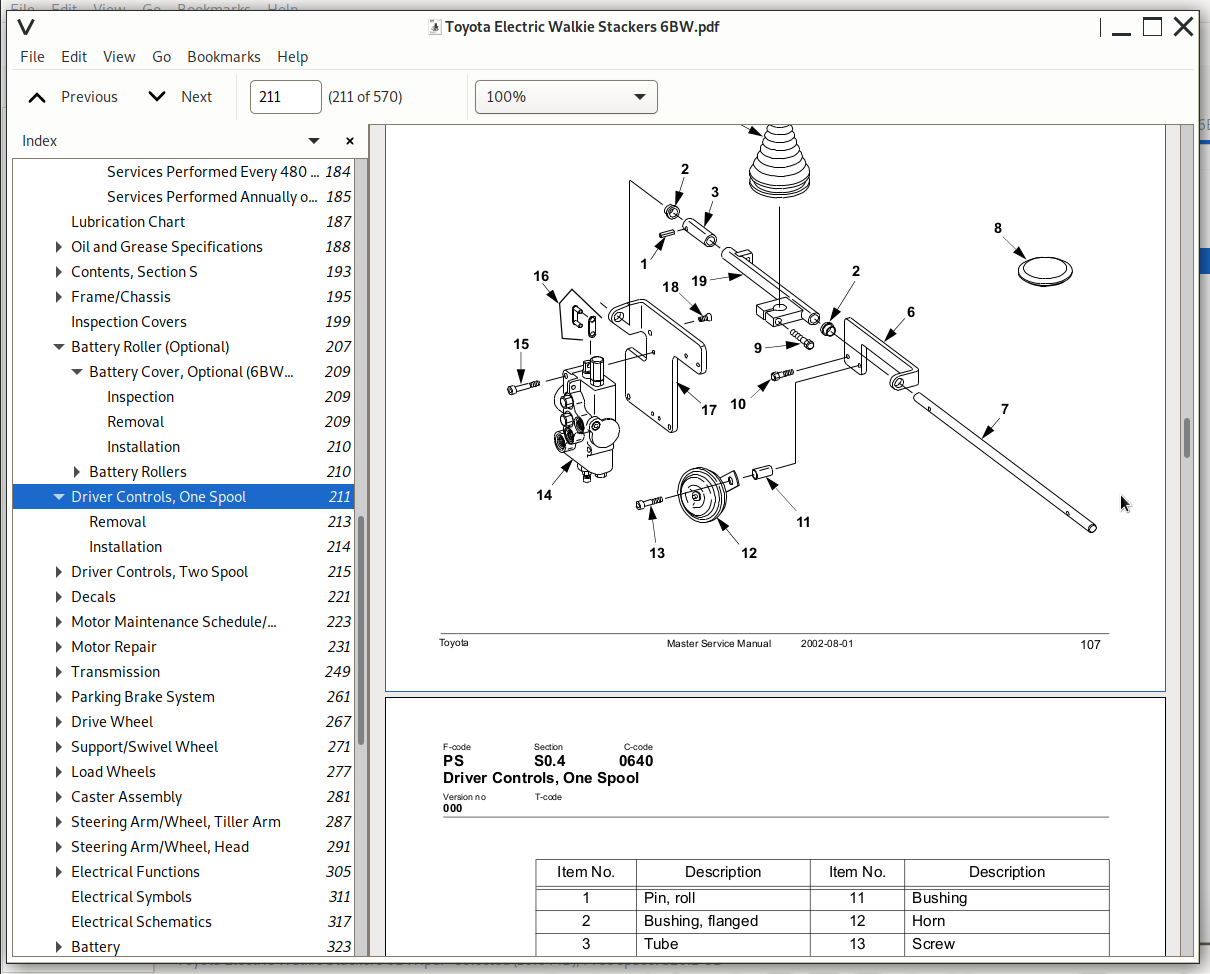
Driver Controls, One Spool....211
Removal....213
Installation....214
Driver Controls, Two Spool....215
Removal....218
Installation....219
Decals....221
Decal with Protective Sheet....221
Decal without Protective Sheet....221
Motor Maintenance Schedule/Troubleshooting....223
General Information....223
Operating Conditions....223
Troubleshooting....224
Motor Repair....231
Pump Motor....231
Pump Motor Removal....232
Pump Motor Installation....232
Drive Motor....233
Brush Replacement....237
Drive Motor Removal....237
Drive Motor Installation....238
Component Repair....240
Disassembly....240
Inspection....242
Drive End Head....242
Commutator End Head....242
Bearings....242
Brush and Commutator....243
Armature....245
Frame and Field Assembly....246
Assembly/Testing....247
Transmission....249
System Description....249
Troubleshooting....249
Kick Panel....250
Transmission Repair....251
Removal....252
Installation....253
Transmission Assembly....255
Disassembly....256
Assembly....256
Axle Seal....258
Removal....258
Installation....258
Parking Brake System....261
Brake Theory of Operation....263
Brake Adjustment....264
Brake Shoe Removal / Installation....265
Drive Wheel....267
Removal....267
Installation....268
Tire Pressing Procedure....269
Support/Swivel Wheel....271
Maintenance and Adjustments....274
Caster Adjustment....275
Troubleshooting....276
Stabilizing Caster....276
Load Wheels....277
Removal and Installation....280
Caster Assembly....281
Disassembly....282
Inspection....283
Assembly....284
Installation....285
Steering Arm/Wheel, Tiller Arm....287
Removal....288
Inspection....289
Installation....290
Steering Arm/Wheel, Head....291
Control Handle Head....292
Removal....292
Installation....292
Direction Control Switches....293
Raise, Lower, and Horn Switches....295
Potentiometer....298
Removal....298
Installation....299
Reverser Assembly Replacement....303
Electrical Functions....305
General....305
Adjustable Settings....305
References....305
Key Switch S17 in ON Position....306
Operating Arm in Drive Position, S10, Brake Switch Closed....306
Travel Request, Forks First....306
Travel Request, Forks Trailing....306
Reversing/Motor Brake Forks First to Forks Trailing Direction....307
Reversing/Motor Brake Forks Trailing to Forks First Direction....307
Reverser Switch....307
Lifting Forks....307
Lowering Forks....308
Horn....308
Options....308
Lifting Forks (Manual Valve)....308
Tilting Forks....308
Side Shifting Forks....308
Extend/Retract Forks....309
Electrical Symbols....311
Electrical Schematics....317
Battery....323
Removal....323
Installation....324
Battery Maintenance....325
Battery Inspection and Care....325
Battery Exterior Cleaning....326
Charging....326
Storage....327
Battery History Record....327
Battery Connector....329
Location....329
Inspection....330
Installation....330
200 Amp System Line Contactor....333
Replacement....333
Removal....333
Installation....333
300 Amp System Line Contactor (6BWC15/20 only)....335
Maintenance....335
Removal/Replacement of Contact Tips....336
200/300 Amp System “EE” Line Contactor....337
Maintenance....337
Removal/Replacement of Contact Tips....338
Battery Controller/Hourmeter/Lift Interrupt....341
General Information....341
Electrical....342
Voltage....342
Battery Controller (BC)....343
General Information....343
Reset....345
Key Switch....345
Hourmeter....346
Troubleshooting....346
Battery Discharge Indicator (BDI)....346
Hourmeter....349
Start/Stop Switches....351
General....351
Test/Inspection....351
Master Control On/Off Switch (S21)....353
Inspection....353
Removal....353
Installation....353
Light Assemblies....355
Warning Lights (Option)....355
Removal....357
Installation....357
Travel/Back-up Alarm (Option)....358
Removal....358
Installation....358
Transistor Controller....359
Basics Of Circuit Operation....359
Control Features....361
Maintenance....362
Safety....362
Cleaning....362
Motor Circuit....363
Control Circuit....364
Troubleshooting Guidelines....365
General....367
Shorts to Frame Test....368
Definitions....372
Diagnostics and Troubleshooting....373
Handset Diagnostics....373
Troubleshooting....373
Troubleshooting Chart....375
Technical Specification....380
Troubleshooting Chart Using Handset....381
Transistor Controller Troubleshooting....383
Troubleshooting Chart Index....383
Troubleshooting Charts....384
Hydraulic System....403
General....403
Description of Function....403
Main Components....404
Lift (Solenoid Valve)....404
Lift (Mechanical Valve)....404
Lower (Solenoid Valve)....404
Lower (Mechanical Valve)....404
Relief Pressure....404
Compensating Cylinder....405
Reach (Solenoid Valve)....405
Tilt (Solenoid Valve)....405
Sideshift (Solenoid valve)....405
Maintenance....406
Adjustments....407
Troubleshooting....408
Primary Malfunctions....409
Definitions....410
Removal....411
Installation....413
Hydraulic Schematics....415
Hydraulic Fluid....419
Hydraulic Fluid Selection....419
Changing Hydraulic System Fluid....419
System Draining....420
Refilling System....421
Bleeding Hydraulic System....422
Hydraulic Tank....423
Removal....424
Installation....424
Hydraulic Pump Assembly....425
Disassembly....427
Inspection....428
Assembly....429
One Spool Control Valve....431
Operators Controls Removal....432
Control Valve Disassembly and Inspection....432
Operators Controls Installation....433
Two Spool Control Valve....434
Operators Controls Removal....435
Control Valve Disassembly and Inspection....435
Operators Controls Installation....436
Lift Cylinder, Two Stage Mast....441
Removal....441
Disassembly....442
Assembly....442
Installation....442
Two Stage Full Freelift Mast Cylinder Repair....443
Removal....443
Disassembly....444
Assembly....444
Installation....444
Two Stage Full Freelift Mast Staging Cylinder Repair....445
Removal....445
Disassembly....446
Assembly....446
Installation....446
Lift Cylinder, Three Stage Mast....447
Repair....450
Removal....450
Disassembly....451
Assembly....451
Installation....451
Reach Cylinder, 6BWR15....453
Removal....455
Disassembly....456
Inspection....457
Assembly....458
Installation....459
Tilt Cylinder....461
Removal....463
Disassembly....464
Inspection....465
Assembly....466
Installation....467
Removal....469
Disassembly....470
Inspection....471
Assembly....472
Installation....473
Shimming Carriage with Mast on Truck....503
Repair....505
Removal....505
Disassembly....506
Assembly....507
Installation....509
Lift Chain....510
Lift Chain Adjustment....488
Lift Chain Maintenance....488
Lift Chain Inspection....488
Lift Chain Replacement....495
Mast, Three Stage....497
Shimming Carriage with Mast on Truck....503
Repair....505
Removal....505
Disassembly....506
Assembly....507
Installation....509
Lift Chain....510
Sideshifter....511
Mounting Instructions....513
Installation....513
Operation....514
Maintenance....514
Carriage Removal....515
Upper Pad Replacement....515
Lower Pad Replacement....516
Cylinder....517
Troubleshooting....518
No Sideshifting....518
Very Slow Sideshifting....518
Irregular Sideshifting....519
Single Reach, 6BWR....521
Maintenance....523
Inspection....523
Adjustment....524
Repair....528
Disassembly....528
Assembly....530
Carriage Bumpers....532
Reach Adjustment....532
Fork Carriage Pivot Pins....534
Carriage Roller Bearings....534
Removal....534
Installation....534
Removal....536
Inspection....536
Installation....537
Load Backrest....539
Removal....540
Installation....540
Handset Operation....541
Operating Modes....544
Revert to Previous Settings....547
Handset Self Test....547
Electrical Controllers (Handset)....549
Display Screen....550
Menu Navigation Key....550
Data Inc/Dec Key....550
Bookmark Keys....550
Operation....551
Menu Structure....551
Main Menu....552
Interface Protocols and Backward Compatibility....553
Parameter Changing....554
Real-Time Monitoring....554
Reading Faults and Diagnostic History File....555
Cloning and Restoring the Previous Programming....555
Information Displays....556
Programmer SetUp....556
Index....557
Circuit Diagrams....561
List of Symbols....566
![]()