
Toyota Stacker Pallet Models LOP10/LOP20/LOP10CW/CF Repair Service Manual
Complete service repair manual with Electrical Wiring Diagrams for Toyota Stacker Pallet Models LOP10, LOP20, LOP10CW, LOP10CF, with all the technical information to maintain, diagnose, repair, rebuild like professional mechanics.
Toyota Stacker Pallet Models LOP10/LOP20/LOP10CW/CF workshop service repair manual includes:
* Numbered table of contents easy to use so that you can find the information you need fast.
* Detailed sub-steps expand on repair procedure information
* Numbered instructions guide you through every repair procedure step by step.
* Troubleshooting and electrical service procedures are combined with detailed wiring diagrams for ease of use.
* Notes, cautions and warnings throughout each chapter pinpoint critical information.
* Bold figure number help you quickly match illustrations with instructions.
* Detailed illustrations, drawings and photos guide you through every procedure.
* Enlarged inset helps you identify and examine parts in detail.
PRODUCT DETAILS:
Total Pages: 431 pages
File Format: PDF (Internal Links, Bookmarked, Table of Contents, Searchable, Printable, high quality)
Language: English
216867-040 - Toyota Stacker Pallet LOP10 Service Manual (Valid from serial number 595874-).pdf
216868-040 - Toyota Stacker Pallet LOP20 Service Manual (Valid from serial number 595874-).pdf
216869-040 - Toyota Stacker Pallet LOP10CW_CF Service Manual (Valid from serial number 595874-).pdf
MAIN SECTIONS
216867-040 - Toyota Stacker Pallet LOP10 Service Manual (Valid from serial number 595874-).....1
1- Table of contents.....3
2- Technical service data - M4.....11
3- Introduction, maintenance - P1.....15
3.1 Safety regulations with maintenance work.....15
3.2 Cleaning and washing.....17
3.2.1 External cleaning.....17
3.2.2 Cleaning the motor compartment.....17
3.2.3 Electrical components.....17
3.3 Safe lifting.....18
4- Preventive maintenance - P2.....19
4.1 Maintenance schedule.....19
4.2 Lubrication table for LOP10.....25
5- Oil and grease specification - P3.....27
5.1 Approved oil’s and grease for LOP10.....27
6- Electric drive motor - 1760.....29
6.1 General.....29
6.1.1 Mechanical structure.....30
6.1.2 Special tools.....31
6.2 Removal/assembly.....31
6.2.1 Removing the motor from the truck.....31
6.2.2 Installing the motor in the truck.....32
6.3 Service/repairs.....33
6.3.1 Cleaning.....33
6.3.2 Removing the motor.....34
6.3.3 Installing the motor.....35
6.3.4 Rotor bearing.....36
Changing the drive end bearing.....36
Changing the commutator end bearing.....37
6.3.5 Carbon brushes and brush holder.....37
Replacing carbon brushes.....37
6.3.6 Commutator.....38
Regrinding the commutator.....38
6.4 Storage/transport.....39
6.4.1 Storage.....39
6.5 Data.....40
7- Transmission, Gear - 2550.....41
7.1 General description.....41
7.1.1 Gear components.....42
7.1.2 Gear data.....43
7.2 Dismantling/fitting of gear from/in truck.....44
7.2.1 Dismantling.....44
7.2.2 Fitting.....45
7.3 Filling of oil.....45
7.4 Exchange of oil.....46
7.5 Exchange of drive shaft seal ring.....47
7.5.1 Dismantling.....47
7.5.2 Assembly.....48
7.6 Leakage from the top cover.....49
8- Electromagnetic brake - 3370.....51
8.1 General description.....51
8.1.1 Function LOP10.....51
8.2 Main brake components.....52
8.3 Maintenance.....53
8.4 Adjusting the gap.....53
8.5 Adjusting the brake force.....54
8.6 Replacing the brake disc.....54
9- Castor wheel - 3540.....55
9.1 General.....55
9.2 Main component of castor wheel.....56
9.3 Maintenance.....58
9.3.1 Checking the height of the castor wheel.....58
9.3.2 Adjusting the castor wheel height.....59
The castor wheel must be adjusted in the following circumstances:.....59
Adjustment procedure.....59
9.3.3 Replacing the castor wheel.....60
Removing the castor wheel assembly.....60
9.3.4 Changing the wheel.....60
Removal.....60
Assembly.....60
9.3.5 Changing the wheel bearing.....61
10- Tiller arm with servo - 4110.....63
10.1 General.....63
10.2 Electrical diagram.....64
10.3 Adjustment.....65
10.3.1 Instruction for adjustments.....66
11- Electric wheel/lever steering - 4310.....69
11.1 General.....69
11.2 Adjustments.....69
11.3 Electrical diagram.....70
12- Electrical system - 5000.1 Tiller arm.....71
12.1 Electrical panel, components.....71
12.2 List of symbols and electrical diagrams.....72
12.2.1 Electrical diagram 1 (7).....75
12.2.2 Electrical diagram 2 (7).....76
12.2.3 Electrical diagram 3 (7).....77
12.2.4 Electrical diagram 4 (7).....78
12.2.5 Electrical diagram 5 (7).....79
12.2.6 Electrical diagram 6 (7).....80
12.2.7 Electrical diagram 7 (7).....81
12.3 Description of function.....82
12.3.1 General.....82
12.3.2 Adjustable settings.....82
12.3.3 References.....82
12.3.4 Ignition lock S17 in the ON position.....83
12.3.5 Starting.....83
Starting for first time after S17 closes or the emer gency switch off is released (S21, S22).....83
Normal start with S17 closed.....83
12.3.6 Driving, steer wheel direction.....83
12.3.7 Driving, fork direction.....83
12.3.8 Braking.....84
12.3.9 Reversing/motor brake.....84
12.3.10 Auto-plug braking.....84
12.3.11 Lifting the forks.....85
12.3.12 Lowering the forks.....85
12.3.13 Lowering the forks from the side.....85
12.3.14 Horn.....85
12.4 Options.....86
12.4.1 Extra emergency switch off (electrical diagram 2).....86
12.4.2 Lifting the forks from the side.....86
12.4.3 Driving from the side of the truck.....86
Function: (electrical diagram 1-3).....86
12.4.4 Inching speed.....87
Function: (electrical diagram 3).....87
12.4.5 Operator lift platform, electrical diagram 6.....87
Lifting the platform.....87
Speed reduction at platform height 500 mm above the floor.....88
Platform lift limit switch.....88
Lowering the platform.....88
13- Electrical system - 5000.2 Steering wheel.....89
13.1 List of symbols and electrical diagrams.....89
13.1.1 List of symbols.....89
13.1.2 Electrical diagram (1/8).....92
13.1.3 Electrical diagram (2/8).....93
13.1.4 Electrical diagram (3/8).....94
13.1.5 Electrical diagram (4/8).....95
13.1.6 Electrical diagram (5/8).....96
13.1.7 Electrical diagram (6/8).....97
13.1.8 Electrical diagram (7/8).....98
13.1.9 Electrical diagram (8/8).....99
13.2 Description of function.....100
13.2.1 General.....100
13.2.2 References:.....100
13.2.3 Ignition lock S17 in the ON position.....100
13.2.4 Brake.....101
Adaption of parking brake.....101
Release of parking brake.....101
Braking during driving.....101
13.2.5 Driving, steer wheel direction.....101
13.2.6 Driving, fork direction.....102
13.2.7 Motor brake (reversing).....102
13.2.8 Auto-plug braking.....102
13.2.9 Lifting the forks.....103
13.2.10 Lowering the forks (from the platform).....103
13.2.11 Lowering the forks from the side.....103
13.2.12 Horn.....103
13.3 Options.....104
13.3.1 Extra emergency switch off (circuit diagram 2).....104
13.3.2 Lifting the forks from the side.....104
13.3.3 Push buttons for driving from the side.....104
Function: (circuit diagram 1-3).....104
13.3.4 Inching speed.....105
Function: (circuit diagram 3).....105
13.3.5 Operator lift platform, circuit diagram 6.....105
Lifting the platform.....105
Speed reduction at platform height 500 mm above the floor.....106
Platform lift limit switch.....106
Lowering the platform.....106
14- Transistor Controller, PUB 24220 CD3 - 5460.....107
14.1 Transistor controller.....107
14.2 Motor circuit.....108
14.3 Control circuit.....108
14.4 Technical specification.....109
14.5 LED indications.....110
14.6 Maintenance.....111
14.6.1 Safety.....111
14.6.2 Cleaning.....111
14.7 Test of transistor unit safety circuit.....112
15- Logic card - 5710.1 Tiller arm.....113
15.1 General description.....113
15.2 Connections and adjustments.....114
15.3 DIP-switch adjustments/settings.....115
15.4 Card pin connections and LEDs.....116
15.5 Speed limit.....120
15.5.1 LOP10.....120
15.6 Fault/error indications.....121
16- Logic card - 5710.2 Steering wheel.....123
16.1 General description.....123
16.2 Basic settings and adjustments.....124
16.2.1 Parameter settings:.....124
16.2.2 Setting the battery size/type.....127
16.3 Board connections and LEDs.....128
16.4 Speed limit.....132
16.4.1 LOP10.....132
16.5 Error codes.....133
16.6 Error code register.....134
17- Hydraulic system - 6000.1.....135
17.1 General.....135
17.2 Description of function.....136
17.2.1 Hydraulic diagram and components.....136
17.2.2 Main components.....137
17.2.3 Description.....137
Lifting the forks.....137
Lowering the forks.....137
Operating pressure.....137
Relief valve.....137
Pressure switch, S61.....138
Pressure switch, S62.....138
18- Hydraulic system - 6000.2 With platform lift.....139
18.1 General.....139
18.2 Description of function.....140
18.2.1 Hydraulic diagram and components.....140
18.2.2 Main components.....141
18.2.3 Description.....141
Lifting the forks.....141
Lowering the forks.....141
Lifting the platform.....141
Lowering the platform.....142
Operating pressure.....142
Relief valve.....142
Flow restrictor for the platform cylinder.....142
Pressure switch, S61.....142
Pressure switch, S62.....142
216868-040 - Toyota Stacker Pallet LOP20 Service Manual (Valid from serial number 595874-).....145
1- Table of contents.....147
2- General product information - M2.....155
2.1 General description.....155
2.1.1 Intended application of LOP20.....156
2.1.2 Forbidden application of LOP20.....156
2.2 Truck data.....157
2.3 Truck dimensions.....158
2.4 Presentation of main components.....159
2.5 Controls and instruments.....162
2.5.1 Truck with tiller arm.....162
2.5.2 Truck with electrical steering wheel.....163
2.6 Signs on the truck.....164
3- Technical service data - M4.....165
4- Introduction, maintenance - P1.....169
4.1 Safety regulations with maintenance work.....169
4.2 Cleaning and washing.....171
4.2.1 External cleaning.....171
4.2.2 Cleaning the motor compartment.....171
4.2.3 Electrical components.....171
4.3 Safe lifting.....172
5- Preventive maintenance - P2.....173
5.1 Maintenance schedule.....173
5.2 Lubrication table for LOP20.....178
6- Oil and grease specification - P3.....179
6.1 Approved oil’s and grease for LOP20.....179
7- Fork unit - 0380.....181
7.1 General description.....181
7.2 Main components of the fork unit.....182
7.3 Dismantling/fitting the fork unit from/to the chassis.....183
7.3.1 Dismantling.....184
7.3.2 Fitting.....184
7.4 Maintenance.....185
Re-assemble.....185
7.5 Exchange of push rods and bush- ings.....186
7.5.1 Dismantling.....186
7.5.2 Re-assemble.....187
8- Electric drive motor - 1760.....189
8.1 General.....189
8.1.1 Mechanical structure.....190
8.1.2 Special tools.....191
8.2 Removal/assembly.....192
8.2.1 Removing the motor from the truck.....192
8.2.2 Installing the motor in the truck.....193
8.3 Service/repairs.....194
8.3.1 Cleaning.....194
8.3.2 Removing the motor.....195
8.3.3 Installing the motor.....196
8.3.4 Rotor bearing.....197
Changing the drive end bearing.....198
Changing the commutator end bearing.....198
8.3.5 Carbon brushes and brush holder.....199
Replacing carbon brushes.....199
8.3.6 Commutator.....200
Regrinding the commutator.....200
8.4 Storage/transport.....201
8.4.1 Storage.....201
8.5 Data.....202
9- Transmission, Gear - 2550.....203
9.1 General description.....203
9.1.1 Gear components.....204
9.1.2 Gear data.....205
9.2 Dismantling/fitting of gear from/in truck.....206
9.2.1 Dismantling.....206
9.2.2 Fitting.....207
9.3 Filling of oil.....207
9.4 Exchange of oil.....208
9.5 Exchange of drive shaft seal ring.....209
9.5.1 Dismantling.....209
9.5.2 Assembly.....210
9.6 Leakage from the top cover.....211
10- Electromagnetic brake - 3370.....213
10.1 General description.....213
10.1.1 Function LOP20.....213
10.2 Main brake components.....214
10.3 Maintenance.....215
10.4 Adjusting the gap.....215
10.5 Adjusting the brake force.....216
10.6 Replacing the brake disc.....216
11- Castor wheel - 3540.....217
11.1 General.....217
11.2 Main component of castor wheel.....218
11.3 Maintenance.....220
11.3.1 Checking the height of the castor wheel.....220
11.3.2 Adjusting the castor wheel height.....221
The castor wheel must be adjusted in the following circumstances:.....221
Adjustment procedure.....221
11.3.3 Replacing the castor wheel.....222
Removing the castor wheel assembly.....222
11.3.4 Changing the wheel.....222
Removal.....222
Assembly.....222
11.3.5 Changing the wheel bearing.....223
12- Tiller arm with servo - 4110.....225
12.1 General.....225
12.2 Electrical diagram.....226
12.3 Adjustment.....227
12.3.1 Instruction for adjustments.....228
13- Electric wheel/lever steering - 4310.....231
13.1 General.....231
13.2 Adjustments.....231
13.3 Electrical diagram.....232
14- Electrical system - 5000.1 Tiller arm.....233
14.1 Electrical panel, components.....233
14.2 List of symbols and electrical diagrams.....234
14.2.1 Electrical diagram 1 (6).....237
14.2.2 Electrical diagram 2 (6).....238
14.2.3 Electrical diagram 3 (6).....239
14.2.4 Electrical diagram 4 (6).....240
14.2.5 Electrical diagram 5 (6).....241
14.2.6 Electrical diagram 6 (6).....242
14.3 Description of function.....243
14.3.1 General.....243
14.3.2 Adjustable settings.....243
14.3.3 References.....243
14.3.4 Ignition lock S17 in the ON position.....244
14.3.5 Starting.....244
Starting for first time after S17 closes or the emer gency switch off is released (S21, S22).....244
Normal start with S17 closed.....244
14.3.6 Driving.....244
14.3.7 Driving, fork direction.....245
14.3.8 Braking.....245
14.3.9 Reversing/motor brake.....245
14.3.10 Auto-plug braking.....246
14.3.11 Lifting the forks.....246
14.3.12 Lowering the forks.....246
14.3.13 Horn.....246
14.4 Options.....247
14.4.1 Extra emergency switch off (electrical diagram 2).....247
14.4.2 Driving from the side of the truck.....247
Function: (electrical diagram 1-3).....247
14.4.3 Inching speed.....248
Function: (electrical diagram 3).....248
14.4.4 Operator lift platform, electrical diagram 6.....248
Lifting the platform.....248
Speed reduction at platform height 500 mm above the floor.....248
Platform lift limit switch.....249
Lowering the platform.....249
14.4.5 Lifting and lowering of the forks.....249
Lifting the forks.....249
Lowering the forks.....249
15- Electrical system - 5000.2 Steering wheel.....251
15.1 List of symbols and electrical diagrams.....251
15.1.1 List of symbols.....251
15.1.2 Electrical diagram (1/7).....254
15.1.3 Electrical diagram (2/7).....255
15.1.4 Electrical diagram (3/7).....256
15.1.5 Electrical diagram (4/7).....257
15.1.6 Electrical diagram (5/7).....258
15.1.7 Electrical diagram (6/7).....259
15.1.8 Electrical diagram (7/7).....260
15.2 Description of function.....261
15.2.1 General.....261
15.2.2 References:.....261
15.2.3 Ignition lock S17 in the ON position.....261
15.2.4 Brake.....262
Adaption of parking brake.....262
Release of parking brake.....262
Braking during driving.....262
15.2.5 Driving, steer wheel direction.....263
15.2.6 Driving, fork direction.....263
15.2.7 Motor brake (reversing).....263
15.2.8 Auto-plug braking.....264
15.2.9 Lifting the forks.....264
15.2.10 Lowering the forks.....264
15.2.11 Horn.....264
15.3 Options.....265
15.3.1 Extra emergency switch off (circuit diagram 2).....265
15.3.2 Push buttons for driving from the side.....265
Function: (circuit diagram 1-3).....265
15.3.3 Inching speed.....266
Function: (circuit diagram 3).....266
15.3.4 Operator lift platform, circuit diagram 6.....266
Lifting the platform.....266
Speed reduction at platform height 500 mm above the floor.....267
Platform lift limit switch.....267
Lowering the platform.....267
15.3.5 Lifting and lowering of the forks.....267
Lifting the forks.....267
Lowering the forks.....268
16- Transistor Controller, PUB 24220 CD3 - 5460.....269
16.1 Transistor controller.....269
16.2 Motor circuit.....270
16.3 Control circuit.....270
16.4 Technical specification.....271
16.5 LED indications.....272
16.6 Maintenance.....273
16.6.1 Safety.....273
16.6.2 Cleaning.....273
16.7 Test of transistor unit safety circuit.....274
17- Logic card - 5710.1 Tiller arm.....275
17.1 General description.....275
17.2 Connections and adjustments.....276
17.3 DIP-switch adjustments/settings.....277
17.4 Card pin connections and LEDs.....278
17.5 Speed limit.....282
17.5.1 LOP20.....282
17.6 Fault/error indications.....283
18- Logic card - 5710.2 Steering wheel.....285
18.1 General description.....285
18.2 Basic settings and adjustments.....286
18.2.1 Parameter settings:.....286
18.2.2 Setting the battery size/type.....288
18.3 Board connections and LEDs.....289
18.4 Speed limit.....293
18.4.1 LOP20.....293
18.5 Error codes.....294
18.6 Error code register.....295
19- Hydraulic system - 6000.1.....297
19.1 General.....297
19.2 Description of function.....297
19.1.1 Main components.....298
19.1.2 Description.....298
Lift.....298
Lower.....298
Operating pressure.....298
Relief valve.....298
Pressure switch.....298
20- Hydraulic system - 6000.2 With platform lift.....299
20.1 General.....299
20.2 Description of function.....300
20.2.1 Hydraulic diagram and components.....300
20.2.2 Main components.....301
20.2.3 Description.....301
Lifting the forks.....301
Lowering the forks.....301
Lifting the platform.....301
Lowering the platform.....302
Operating pressure.....302
Relief valve.....302
Flow restrictor for the platform cylinder.....302
Pressure switch, S61.....302
216869-040 - Toyota Stacker Pallet LOP10CW_CF Service Manual (Valid from serial number 595874-).....305
1- Table of contents.....307
2- General product information - M2.1.....315
2.1 General description.....315
2.1.1 Intended application of the truck.....315
2.1.2 Forbidden application of the truck.....315
2.2 Truck data.....316
2.3 Truck dimensions.....317
2.4 Main components.....318
2.5 Controls and instruments.....320
2.6 Warning and information plates and symbols.....321
3- General product information - M2.2.....323
3.1 General description.....323
3.1.1 Intended application of the truck.....323
3.1.2 Forbidden application of the truck.....323
3.2 Truck data.....324
3.3 Truck dimensions.....325
3.4 Main components.....326
3.5 Controls and instruments.....328
3.6 Warning and information plates and symbols.....329
4- Technical service data - M4.....331
5- Introduction, maintenance - P1.....335
5.1 Safety regulations with maintenance work.....335
5.2 Cleaning and washing.....337
5.2.1 External cleaning.....337
5.2.2 Cleaning the motor compartment.....337
5.2.3 Electrical components.....337
5.3 Safe lifting.....338
6- Preventive maintenance - P2.....339
6.1 Maintenance schedule.....339
6.2 Lubrication table for LOP10CW/CF.....344
7- Oil and grease specification - P3.....345
7.1 Approved oil’s and grease for LOP10CW/CF.....345
8- Electric drive motor - 1760.....347
8.1 General.....347
8.1.1 Mechanical structure.....348
8.1.2 Special tools.....349
8.2 Removal/assembly.....349
8.2.1 Removing the motor from the truck.....349
8.2.2 Installing the motor in the truck.....350
8.3 Service/repairs.....351
8.3.1 Cleaning.....351
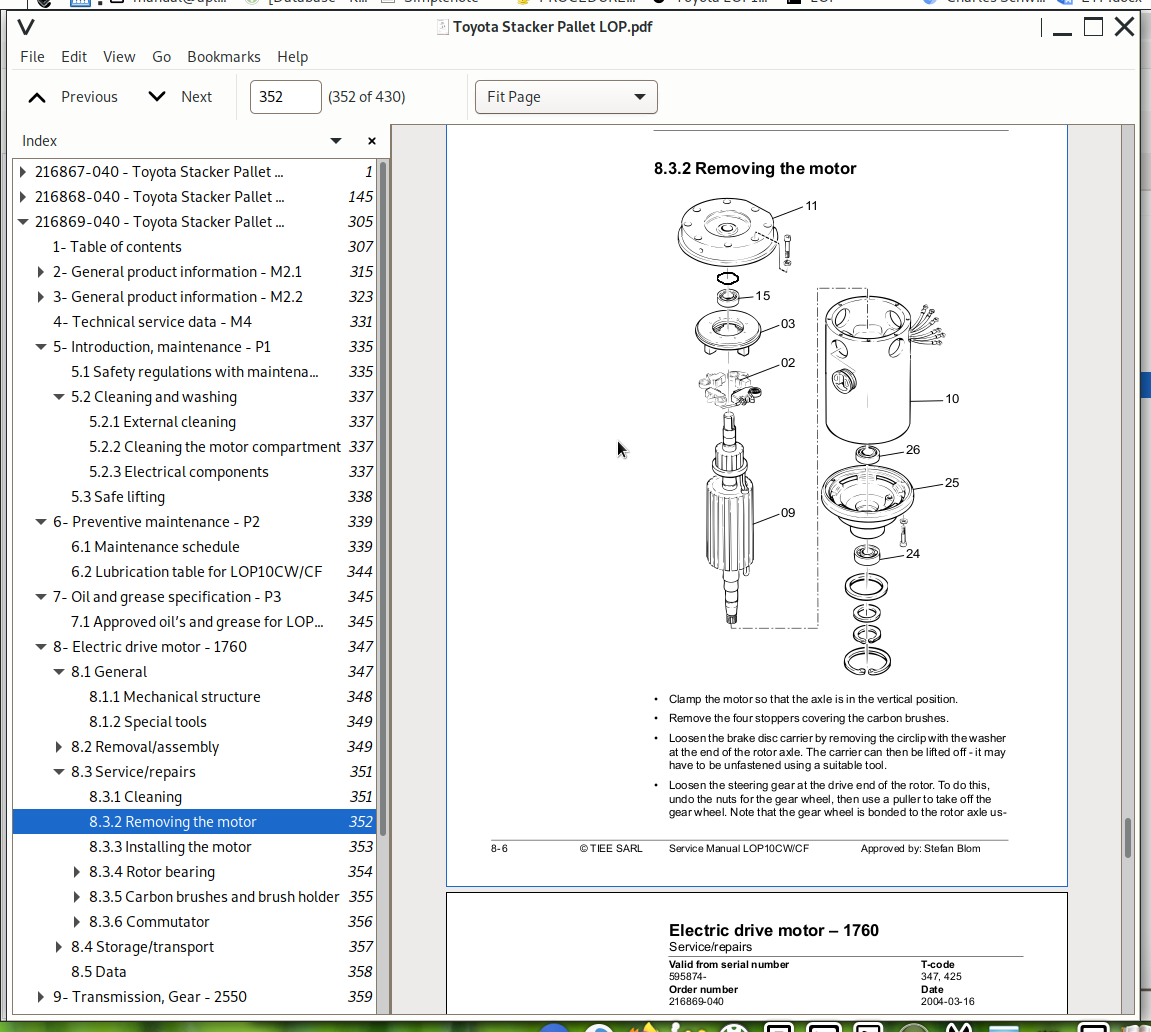
8.3.2 Removing the motor.....352
8.3.3 Installing the motor.....353
8.3.4 Rotor bearing.....354
Changing the drive end bearing.....354
Changing the commutator end bearing.....355
8.3.5 Carbon brushes and brush holder.....355
Replacing carbon brushes.....355
8.3.6 Commutator.....356
Regrinding the commutator.....356
8.4 Storage/transport.....357
8.4.1 Storage.....357
8.5 Data.....358
9- Transmission, Gear - 2550.....359
9.1 General description.....359
9.1.1 Gear components.....360
9.1.2 Gear data.....361
9.2 Dismantling/fitting of gear from/in truck.....362
9.2.1 Dismantling.....362
9.2.2 Fitting.....363
9.3 Filling of oil.....363
9.4 Exchange of oil.....364
9.5 Exchange of drive shaft seal ring.....365
9.5.1 Dismantling.....365
9.5.2 Assembly.....366
9.6 Leakage from the top cover.....367
10- Electromagnetic brake - 3370.....369
10.1 General description.....369
10.1.1 Function LOP10CW/CF.....369
10.2 Main brake components.....370
10.3 Maintenance.....371
10.4 Adjusting the gap.....371
10.5 Adjusting the brake force.....372
10.6 Replacing the brake disc.....372
11- Castor wheel - 3540.....373
11.1 General.....373
11.2 Main components.....374
11.3 Maintenance.....375
11.3.1 Inspection procedure, castor wheel pressure.....375
11.3.2 Adjusting the castor wheel pressure.....376
The castor wheel must be adjusted in the following circumstances:.....376
Adjustment procedure.....376
11.3.3 Replacing the castor wheel.....377
Removing the entire castor wheel unit.....377
11.3.4 Changing the wheel.....378
11.3.5 Lubricating the pivot bearing.....378
11.3.6 Adjusting the play of the pivot bearing.....378
12- Electric wheel/lever steering - 4310.....379
12.1 General.....379
12.2 Adjustments.....379
12.3 Electrical diagram.....380
13- Electrical system - 5000.....381
13.1 List of symbols and electrical diagram.....381
13.1.1 List of symbols.....381
13.1.2 Electrical diagram (1/8).....384
13.1.3 Electrical diagram (2/8).....385
13.1.4 Electrical diagram (3/8).....386
13.1.5 Electrical diagram (4/8).....387
13.1.6 Electrical diagram (5/8).....388
13.1.7 Electrical diagram (6/8).....389
13.1.8 Electrical diagram (7/8).....390
13.1.9 Electrical diagram (8/8).....391
13.2 Functional description.....392
13.2.1 General.....392
13.2.2 References.....392
13.2.3 Ignition switch S17 on.....392
13.2.4 Brake.....393
Applying the parking brake.....393
Releasing the parking brake.....393
Braking during operation.....393
13.2.5 Operation, direction of steer wheel.....394
13.2.6 Operation, direction of forks.....394
13.2.7 Motor brake (reversing).....394
13.2.8 Automatic plug-braking.....395
13.2.9 Cabin lift.....395
13.2.10 Cabin lower.....395
13.2.11 Fork lift (LOP10CF).....395
13.2.12 Fork lower (LOP10CF).....395
13.2.13 Horn.....396
13.3 Options.....396
13.3.1 Additional emergency switch off, electrical diagram 2.....396
13.3.2 Walking operation from side of truck.....396
Function, electrical diagram 1-3.....396
14- Transistor Controller, PUB 24220 CD3 - 5460.....397
14.1 Transistor controller.....397
14.2 Motor circuit.....398
14.3 Control circuit.....398
14.4 Technical specification.....399
14.5 LED indications.....400
14.6 Maintenance.....401
14.6.1 Safety.....401
14.6.2 Cleaning.....401
14.7 Test of transistor unit safety circuit.....402
15- Logic card - 5710.....403
15.1 General.....403
15.2 Basic settings and adjustments.....404
15.2.1 Parameter settings:.....404
15.2.2 Setting the battery size/type.....407
15.3 Board connections and LEDs.....408
15.4 Speed limits.....412
15.4.1 LOP10CW/CF.....412
15.5 Fault codes.....413
15.6 Error code register.....414
16- Hydraulic system - 6000.1.....415
16.1 General.....415
16.2 Functional description.....415
16.2.1 Diagram of hydraulic system and components.....415
16.2.2 Main components.....416
16.2.3 Description.....416
Lift.....416
Lower.....416
Operating pressure.....416
Pressure relief valve.....416
Pressure switch.....417
16.3 Adjustments.....417
16.3.1 Adjusting the pressure control valve.....417
17- Hydraulic system - 6000.2.....419
17.1 General.....419
17.2 Functional description.....420
17.2.1 Diagram of hydraulic system and components.....420
17.2.2 Main components.....421
17.2.3 Description.....422
Fork lift.....422
Fork lower.....422
Operating pressure.....422
Safety valve.....422
18- Main lift chain system - 7120.....423
18.1 General.....423
18.2 Checking the chain setting.....423
18.3 Chain inspection.....423
18.3.1 Noise.....423
18.3.2 Surface rust.....423
18.3.3 Rusty links.....423
18.3.4 Stiff links.....424
18.3.5 Bolt rotation.....424
18.3.6 Loose bolts.....424
18.3.7 Outline wear.....425
18.3.8 Stretching.....426
18.3.9 Damage.....426
18.3.10 Damaged discs.....427
18.3.11 Damaged bolts.....427
18.3.12 Dirty chain.....427
18.4 Cleaning.....427
18.5 Lubrication.....428
![]()