
Toyota 7LOP10CW, 7LOP10CF Order Picking Stacker Pallet Truck Repair Service Manual
Toyota 7LOP10CW, 7LOP10CF Order Picking Stacker Pallet Truck Repair Service Manual
Complete service repair manual with Electrical Wiring Diagrams for Toyota 7LOP10CW, 7LOP10CF Order Picking Stacker Pallet Truck, with all the technical information to maintain, diagnose, repair, rebuild like professional mechanics.
Toyota 7LOP10CW, 7LOP10CF Order Picking Stacker Pallet Truck workshop service repair manual includes:
* Numbered table of contents easy to use so that you can find the information you need fast.
* Detailed sub-steps expand on repair procedure information
* Numbered instructions guide you through every repair procedure step by step.
* Troubleshooting and electrical service procedures are combined with detailed wiring diagrams for ease of use.
* Notes, cautions and warnings throughout each chapter pinpoint critical information.
* Bold figure number help you quickly match illustrations with instructions.
* Detailed illustrations, drawings and photos guide you through every procedure.
* Enlarged inset helps you identify and examine parts in detail.
PRODUCT DETAILS:
Total Pages: 206 pages
File Format: PDF (Internal Links, Bookmarked, Table of Contents, Searchable, Printable, high quality)
Language: English
232370-040 - Toyota 7LOP10CW, 7LOP10CF Order Picking Stacker Pallet Truck Service Manual (Valid from serial number 931876-)
MAIN SECTIONS
2- Technical data.......9
2.1 Tightening torques.......13
2.2 General tightening torques.......14
3- Maintenance.......15
3.1 Safety rules during maintenance work.......15
3.2 Cleaning and washing.......17
3.2.1 External cleaning.......17
3.2.2 Cleaning the motor compartment.......17
3.2.3 Electric components.......17
3.3 Safe lifting.......18
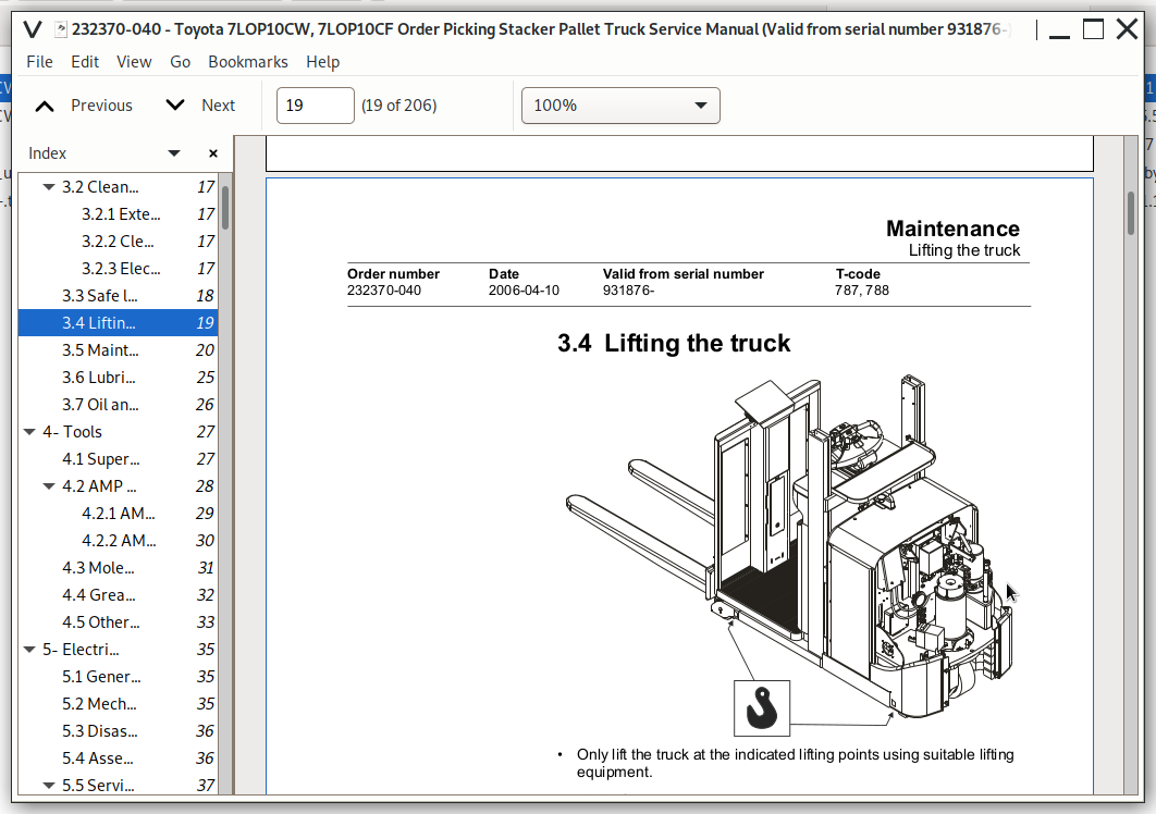
3.4 Lifting the truck.......19
3.5 Maintenance schedule.......20
3.6 Lubrication schedule.......25
3.7 Oil and lubricant specifications.......26
4- Tools.......27
4.1 Super Seal connectors.......27
4.2 AMP connectors.......28
4.2.1 AMP Connectors, 040 series.......29
4.2.2 AMP connectors CPC.......30
4.3 Molex connectors.......31
4.4 Grease guns.......32
4.5 Other tools.......33
5- Electric drive motor - 1760.......35
5.1 General.......35
5.2 Mechanical design.......35
5.3 Disassembly of the motor from the truck.......36
5.4 Assembly of the motor in the truck.......36
5.5 Service and repairs.......37
5.5.1 Disassembly of the motor.......37
5.5.2 Disassembly, N side.......38
5.5.3 Disassembly, D side.......38
5.5.4 Wearing parts.......38
5.5.5 Cleaning.......39
6- Driving unit/gear - 2550.......41
6.1 Included components.......42
6.2 Disassembly/Assembly Leakage from top cover.......43
Assembly is done in reverse........43
6.3 Replacing the drive axle jointing ring.......44
6.3.1 Disassembly.......44
6.3.2 Assembly.......45
6.4 Replacing the wheel bolt.......46
7- Electromagnetic brake - 3370.......47
7.1 Included components.......48
7.2 Disassembly.......48
7.2.1 Inspection.......48
7.3 Assembly.......49
7.4 Manual release of the brake.......49
7.5 Adjustment.......49
7.5.1 Adjusting the play.......49
8- Support wheels - 3500.......51
8.1 Main components.......51
8.1.1 Replacing the wheel.......52
Disassembly.......52
Assembly.......52
8.1.2 Replacing the wheel bearings.......52
9- Electrical steering system - 4300.......53
9.1 General.......53
9.1.1 Electrical steering servo.......54
9.2 Component overview.......55
9.3 Adjustment.......57
9.3.1 Reference sensor.......57
9.3.2 Calibration.......57
Parameter 36.......57
Parameter 37.......57
9.4 Disassembly/assembly of pushbuttons.......58
9.4.1 Replacing the hornbutton/switch.......58
9.4.2 Replacing the lifting/lowering pushbutton.......59
9.4.3 Replacing the pushbutton.......59
9.5 Replacing the potentiometer.......60
9.6 Replacing the inductive brake sensor.......63
9.7 Replacing the viscous damper.......66
10- Electrical systems - 5000.......69
10.1 General.......69
10.1.1 Software/hardware order numbers.......69
10.1.2 Nomenclature.......70
10.2 Electrical equipment overview.......71
10.2.1 Electric component overview.......73
10.3 Electrical wiring diagram.......76
10.3.1 Symbol list.......76
10.3.2 Overview.......77
10.3.3 Detailed wiring diagram.......78
10.4 Functional description.......87
10.4.1 Description of steering system.......92
10.4.2 Spider expansion unit (SEU).......93
10.4.3 Speed limitation.......94
10.4.4 Hour meter and battery condition.......95
10.4.5 TLS - Truck log system (optional).......96
General.......96
Registration.......96
Logging in/out SD16.......96
Logging in/out S16.......96
Collision sensor.......97
Settings.......97
10.4.6 ID unit (optional).......98
General.......98
Installation.......98
Settings.......99
10.5 Parameters & adjustments.......101
10.5.1 General.......101
10.5.2 Displaying parameters - without the CAN service key.......101
10.5.3 Adjusting operator parameters - without the CAN service key.......102
10.5.4 Displaying & changing parameters - CAN service key connected.......102
Changing a parameter.......103
10.5.5 List of operator parameters.......104
10.5.6 Description of operator parameters.......105
#1 - Speed, Fork direction.......105
# 2 - Speed, Drive wheel direction.......105
# 3 - Acceleration.......105
# 4 - Neutral braking force.......105
# 5 - Travel speed, cabin > 0.5 m.......105
# 6 - Travel speed, walking at side.......105
# 7 - Neutral braking, walking at side.......105
10.5.7 List of Service parameters.......106
10.5.8 Description of Service parameter.......107
# 10 - PIN code.......107
To enter a new PIN-code:.......108
To remove an existing PIN-code:.......108
# 11 - Reverse braking force.......109
# 14 - Creep speed.......109
#15 - Non-configurable options.......109
Setting Non-configurable options.......109
#16 - Configurable option #1.......110
#17 - Configurable option #2.......110
#19 - Configurable option #4.......110
# 20 - Hour meter selection.......111
# 21 - Battery size.......112
# 22 - Machine type.......113
# 23 - Function selection.......113
# 24 - Special request.......113
# 25 - Service interval.......113
# 28 - Button selection.......113
# 35 - Automatic log-off.......114
# 36 - Steer servo calibration.......114
# 37 - Steering offset.......115
# 39 - Log-in method & operator parameter access.......115
Extended keypad - General.......116
Extended keypad - Programming.......116
10.5.9 Configurable “Option” parameters.......118
General.......118
Parameter #16 to #19 configurable options.......119
Setting Configurable options.......120
10.6 Diagnostic and troubleshooting.......131
10.6.1 General.......131
10.6.2 Fault code history.......132
10.6.3 List of fault codes.......132
10.6.4 Transistor regulator troubleshooting and error codes.......138
General.......138
Transistor regulator errors.......139
Resetting errors.......140
Safety.......140
10.6.5 Built-in Test Function.......141
Digital inputs/outputs test mode.......142
10.6.6 Transistor regulator inputs.......142
Transistor regulator outputs.......143
Digital input of logic card [A2].......143
Digital input/output to expansion unit [A36].......144
Digital input/output to expansion unit [A36] (Option).......144
Extra functions.......145
10.6.7 Display test mode.......145
10.7 Technical specifications - Curtis 1243.......146
11- Hydraulic system - 6000.......147
11.1 7LOP10CW.......147
11.1.1 General.......147
11.1.2 Hydraulic drawing and symbol list.......148
Symbol list.......148
11.1.3 Description.......149
Lift.......149
Lowering.......149
Operating pressure.......149
Relief valve.......149
Pressure sensor.......149
11.2 7LOP10CF.......150
11.2.1 General.......150
11.2.2 Hydraulic drawing and symbol list.......151
Symbol list.......152
11.2.3 Description.......152
Cabin lifting.......152
Cabin lowering.......152
Initial forks.......153
Initial forks lowering.......153
Operating pressure.......153
Relief valve.......153
Check valve for the cabin / forks cylinders (3).......153
Pressure sensors, B10/B11.......153
11.3 Adjustments.......154
Adjusting the pressure limiting valve.......154
12- Main lift chain system - 7120.......155
12.1 General.......155
12.2 Checking the chain setting.......155
12.3 Chain inspection.......155
12.3.1 Noise.......155
12.3.2 Surface rust.......155
12.3.3 Rusty links.......155
12.3.4 Stiff links.......156
12.3.5 Bolt rotation.......156
12.3.6 Loose bolts.......156
12.3.7 Outline wear.......157
12.3.8 Stretching.......158
12.3.9 Damage.......159
12.3.10 Damaged discs.......159
12.3.11 Damaged bolts.......159
12.3.12 Dirty chain.......159
12.4 Cleaning.......159
12.5 Lubrication.......160
13- Fork carriage - 7420.......161
13.1 Included components.......161
13.2 Dismounting of the mast carriage........163
13.3 Adjusting the play.......163
13.4 Roller replacement.......163
13.5 Dismounting of the initial fork carriage........164
14- TruckCom.......165
14.1 General.......165
14.2 Connection.......165
14.3 Layout.......166
14.3.1 Main program screen.......166
14.3.2 Nodes.......166
14.3.3 Icons.......167
14.3.4 Tool buttons and menu bar.......167
14.3.5 Information window.......168
14.3.6 Status bar.......168
14.4 Connection function.......168
14.5 Disconnection function.......168
14.6 Downloading program function.......169
14.6.1 Normal downloading (truck with key).......169
14.6.2 Normal downloading (truck with keypad).......169
14.6.3 Emergency downloading (truck with keypad).......170
14.6.4 Emergency downloading (truck with keypad).......170
14.6.5 Downloading in old versions of logic card.......170
14.7 Truck report function.......171
14.8 Parameters function.......172
14.9 Diagnostics function.......172
14.9.1 Representation of signal colours.......173
14.9.2 “Tiller arm” tab.......173
14.9.3 “Drive Controller” tab (transistor regulator driving).......174
14.9.4 “Pump controller” tab (transistor regulator pump).......175
14.9.5 “EPS” (steering servo tab).......176
14.9.6 SEU tab (Extra I/O module).......177
14.10 Other menu functions.......177
14.10.1 Save to file.......177
14.10.2 Download from file.......177
14.10.3 Reset CAN adapter.......178
14.10.4 Delete error code log.......178
14.10.5 Reset hour meter.......178
14.10.6 Read error code log.......178
14.10.7 Adjust date and time.......178
14.10.8 Adjusting the hour meter on older cards.......178
14.10.9 Help.......178
About the TruckCom application.......178
14.10.10 Exit.......178
14.11 Specifications.......179
14.12 Installation.......179
14.12.1 Installation on a PC with Windows® 95/98.......179
14.12.2 Installation on a PC with Windows XP/ 2000.......180
Changes in Windows® control panel.......183
14.12.3 Installation on a PC with Windows NT.......186
14.12.4 In case of communication problems with CAN.......186
14.12.5 To uninstall.......186
15- Destruction instructions.......187
15.1 General.......187
15.2 Procedure.......187
15.3 Abbreviations.......188
15.4 Sorting.......188
15.5 Hoods, hatches (0340).......189
15.5.1 Dismantling.......189
15.5.2 Material handling.......189
15.6 Hoods, hatches (0340).......190
15.6.1 Dismantling.......190
15.6.2 Material handling.......190
15.7 Seat, cushions (0620).......191
15.7.1 Dismantling.......191
15.7.2 Material handling.......191
15.8 Wall/floor covering (0670).......192
15.8.1 Dismantling.......192
15.8.2 Material handling.......192
15.9 Electric motors (1700).......193
15.9.1 Dismantling.......193
15.9.2 Material handling.......193
15.10 Drive assembly/gear (2550).......194
15.10.1 Dismantling.......194
15.10.2 Material handling.......194
15.11 Wheels (3500).......195
15.11.1 Dismantling.......195
15.11.2 Material handling.......195
15.12 Steering arm (4110).......196
15.12.1 Dismantling.......196
15.12.2 Material handling.......196
15.13 General electronic equipment (5100).......197
15.13.1 Dismantling.......197
15.13.2 Material handling.......197
15.14 Battery cut out connector/ contactor (5190).......198
15.14.1 Dismantling.......198
15.14.2 Material handling.......198
15.15 Expansion unit “SEU”(5730).......199
15.15.1 Dismantling.......199
15.15.2 Material handling.......199
15.16 Hydraulic unit (6100).......200
15.16.1 Dismantling.......200
15.16.2 Material handling.......200
15.17 Hydraulic lines chassis (6230) and main lift cylinders (6610).......201
15.17.1 Dismantling.......201
15.17.2 Material handling.......201
15.18 Frame/chassis (7420).......202
15.18.1 Dismantling.......202
15.18.2 Material handling.......202
15.19 Charger adaptor (9380).......203
15.19.1 Dismantling.......203
15.19.2 Material handling.......203
15.20 Other extra equipment, tuck log device (9420).......204
15.20.1 Dismantling.......204
15.20.2 Material handling.......204
15.21 Other extra equipment, writing table (9500).......205
15.21.1 Dismantling.......205
15.21.2 Material handling.......205
![]()