
Toyota Reach Lift Truck Model 7BRU18, 7BRU23, 7BDRU15, 7BSU20, 7BSU25 Repair Service Manual
Complete service repair manual with Electrical Wiring Diagrams for Toyota Reach Lift Truck Model 7BRU18, 7BRU23, 7BDRU15, 7BSU20, 7BSU25, with all the technical information to maintain, diagnose, repair, rebuild like professional mechanics.
Toyota Reach Lift Truck Model 7BRU18, 7BRU23, 7BDRU15, 7BSU20, 7BSU25 workshop service repair manual includes:
* Numbered table of contents easy to use so that you can find the information you need fast.
* Detailed sub-steps expand on repair procedure information
* Numbered instructions guide you through every repair procedure step by step.
* Troubleshooting and electrical service procedures are combined with detailed wiring diagrams for ease of use.
* Notes, cautions and warnings throughout each chapter pinpoint critical information.
* Bold figure number help you quickly match illustrations with instructions.
* Detailed illustrations, drawings and photos guide you through every procedure.
* Enlarged inset helps you identify and examine parts in detail.
PRODUCT DETAILS:
Total Pages: 557 pages
File Format: PDF (Internal Links, Bookmarked, Table of Contents, Searchable, Printable, high quality)
Language: English
00700-CL220-01 - Toyota Reach Lift Truck Model 7BRU18, 7BRU23, 7BDRU15, 7BSU20, 7BSU25 Service Manual.pdf
MAIN SECTIONS
R/M 7BRU18-23, 7BDRU15 & 7BSU25 SN: 21,000 & UP - 24 VOLT MODELS & SN: 32,000 & UP - 36 VOLT...1
Table of Contents...I
How to Use This Manual...1
Map of the Manual...2
Manual Design...3
START Page...5
Safety...1
Definitions...2
General Safety...3
Battery Safety...7
Static Safety...11
Figure 2-1: Ground Jack...11
Figure 2-2: Anti-Static Kit with Wrist Strap and Mat...12
Jacking Safety...13
Figure 2-3: Correct Jacking Locations...13
Tie-down for Transport...14
Welding Safety...15
Systems Overview...1
Vehicle Specifications...2
General System Data...3
Brake...4
Steering...4
Lift/Lower System...4
Auxiliary System...4
Traction System...5
Modes of Operation...6
Self-diagnosis Mode...6
Analyzer (AnL) Mode...6
Tuning (Tuning) Mode...6
Calibrate (Calibrte) Mode...6
Configure (Configur) Mode...6
Scheduled Maintenance...1
Maintenance Guidelines...2
Daily or Every 8 Operating Hours...3
Monthly or Every 200 Operating Hours...4
Semi-annually or Every 1000 Operating Hours...5
Annually or Every 2000 Operating Hours...6
Lubricants...7
Cold Storage Conditioning...7
Classes Of Cold Storage...7
Figure 4-1: Recommended Oils by Temperature...7
Lubrication and Inspection Points...9
Figure 4-2: Lubrication and Inspection Points...9
Troubleshooting...1
How to Use This Chapter...2
Electrical Troubleshooting Guidelines...3
Shorts to Frame Test...4
To test for shorts to frame:...4
Figure 5-1: Shorts to Frame Test...6
Hydraulic Troubleshooting Guidelines...8
Definitions...9
Auxiliary Function...9
Continuity...9
Deadman Switch...9
High Speed Travel Limit...9
Mast Assembly...9
Mast Switch...9
Open Circuit...9
Overtemperature (Power Amplifiers)...9
Pulse Width Modulation...9
Short Circuit or “Short”...9
Tractor...9
Undertemperature...9
Electrical Connector Locator Chart...10
Electrical Connector Locator Photos...12
Figure 5-2: Electrical Connectors, Electrical Compartment (Operator Right Side)...12
Figure 5-3: Power Amplifier Connections...13
Figure 5-4: Electrical Connectors, Motor Compartment...14
Figure 5-5: Electrical Connectors, Operator Display/Display Card...15
List of Troubleshooting Flowcharts...17
Hydraulic Charts...17
Travel Charts...17
Wiring Charts...17
TS1: START TROUBLESHOOTING...19
GEN1: General Troubleshooting...20
MISC: Miscellaneous Problems...21
END1: End of Troubleshooting Procedure...22
H-1: Hydraulic Problem with One Function...23
H-2: Lift/Lower Problem...24
H-3: Reach Problem...25
H-4: Retract Problem...26
H-5: Tilt Problem...27
H-6: Sideshift Problem...28
H-7: Hydraulic Problem...29
H-10: Lift Does Not Respond for Lift or Aux. Function...30
H-11: No Lift, Lift Motor Operates...33
H-12: Lift Functions But Works Slow, Lift Motor Runs...38
H-13: Reach Does Not Work...42
H-14: Reach Works Slow...46
H-15: Reach and Lift Pump Do Not Work...49
H-16: Retract Does Not Work...50
H-17: Retract Works Slow...54
H-18: Retract and Lift Pump Do Not Work...57
H-19: Tilt Does Not Work (Up or Down)...58
H-20: Tilt Works Slow...61
H-21: Tilt and Lift Pump Do Not Work...63
H-22: Sideshift Does Not Work (Either Direction)...64
H-23: Sideshift Works Slow...67
H-24: Sideshift and Lift Pump Do Not Work...69
H-25: Load Drifts Down While Forks Are Elevated...70
H-26: Cannot Pick Up A Load...72
H-27: Aux Functions Work Only One Side/Direction...74
H-28: No Lower...76
T-1: Travel Problem...80
T-2: No Travel In Either Direction...81
T-3: Travel In One Direction Only...83
T-4: Problem With Slow Travel...84
T-5: Truck Does Not Accelerate Properly...85
T-6: Plugging Does Not Operate Properly...87
T-18: No Slow Travel Above Mast Switch1...88
T-19: Slow Travel Speed At All Times...89
W-1: Truck Functions Partially...92
Electrical Codes and Tests...1
Modes of Operation...2
Figure 6-1: Menu Structure for Modes of Operation...2
Passwords...3
Disable the Brush Wear Warning...3
Start the Hour Meter...3
Self-diagnosis Mode...4
Maneuvering within Self-diagnosis Mode...4
Adjusting the Date...4
Adjusting the Time...4
Analyzer (AnL) Mode...5
Entering the Secondary Password...5
Entering Analyzer Mode...5
Maneuvering within Analyzer Mode...5
Calibrate (Calibrte) Mode...6
Entering the Secondary Password...6
Entering Calibrate Mode...6
Maneuvering within Calibrate Mode...6
Configure (Configur) Mode...8
Entering the Secondary Password...8
Entering Configure Mode...8
Maneuvering within Configure Mode...8
Exiting Configure Mode...8
Tuning (Tuning) Mode...9
Entering the Secondary Password...9
Maneuvering within Tuning Mode...9
Exiting Tuning Mode...11
Code Summary Table...12
Table 6-1: Steer Controller Codes...82
Table 6-2: Steering Counterclockwise...93
Table 6-3: Steering Clockwise...93
Tests...122
Test 11 - Simple Test...123
Test 12 - Analog Inputs...124
Test 13 - Traction Speed Sensor...127
Test 14 - Throttle/Lift Command Test...128
Test 21 - Error Code Display...129
Test 33 - Switch Input Test...130
Test 34 - Short Circuit Test...131
Test 41 - Drive Unit Proximity Sensor Test (180 Steering)...132
Test 41 - Drive Unit Proximity Sensor Test (360 Steering)...133
Test 51 - Output Test...134
Test 61 - Software Versions...135
Analog Tests (Category 1, Class 2)...136
Test 12-00 - Drive Motor Armature Current...136
Test 12-01 - Drive Motor Field Current...136
Test 12-02 - Traction Pot. Voltage...137
Test 12-03 - Traction Motor Temperature Sensor...137
Test 12-04 - Traction Motor Power Amplifier Temperature Sensor...138
Test 12-05 - Lift Motor Armature Current...138
Test 12-06 - Lift Pot Voltage...138
Test 12-07 - Lift Motor Temperature Sensor...139
Test 12-08 - Lift Motor Power Amplifier Temperature Sensor...139
Test 12-10 - Pressure Transducer...140
Test 12-11 - Battery Voltage...140
Test 12-12 - Stored Battery Voltage...140
Test 12-13 - 12V Supply on the Display Card...141
Test 12-14 - MM Contactor Sense...141
Test 12-15 - EPO Sense...141
Test 12-16 - Left Pedal Pot...142
Component Procedures...1
List of Component Procedures...2
Component Locator Photos...5
Frame and Accessories...13
Panels and Covers...14
General...14
Figure 7-1: Tractor Panels and Covers...14
Console Cover...14
Electrical Compartment Access Panel...15
Motor Compartment Door...15
Left Operator Compartment Panel...16
Left Side Panel...16
Floor Board...18
Figure 7-2: Floor Board Removal...18
Decals...20
Decal with Protective Sheet...20
Decal without Protective Sheet...20
Steering and Controls...21
Steering Wheel...22
Figure 7-3: Steering Wheel Mounting and Components...22
Removal...22
Installation...22
Steer Tachometer...23
Figure 7-4: Steer Tach Mounting...23
Steer Motor...24
Figure 7-5: Steer Motor...24
Figure 7-6: Spacer and O-Rings...24
Figure 7-7: Mounting Bolts and Grommets...25
Steer Motor Gear Replacement...25
Figure 7-8: Steer Motor Gear...25
Steer Controller...26
Figure 7-9: Steer Controller...26
Exterior Cleaning...26
Removal...26
Installation...27
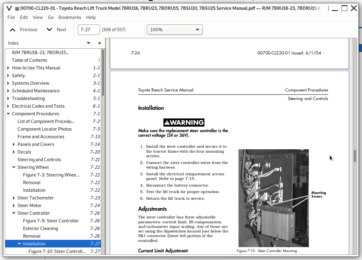
Figure 7-10: Steer Controller Mounting...27
Adjustments...27
Control Handle...29
Figure 7-11: Control Handle...29
Figure 7-12: Control Handle Mounting Screw...29
Figure 7-13: JP10 Connection at Tractor Interface Card...29
Traction and Braking...31
Deadman Pedal...32
Figure 7-14: Deadman Pedal Component Identification...32
Pedal Bearing Replacement...34
Caster Assembly with Brake...35
Figure 7-15: Caster Assembly with Brake Component Identification...35
Caster Brake Adjustment...36
Figure 7-16: Upper Adjustment Location...37
Figure 7-17: Lower Adjustment Location...38
Caster Assembly w/o Brake...41
Figure 7-18: Caster Assembly without Brake Component Identification...41
Caster Pivot...42
Thrust Bearing...44
Figure 7-19: Jacking Location...44
Caster Springs...45
Figure 7-20: Caster Adjustment Springs...45
Caster Axle...47
Caster Stops...48
Electromagnetic Brake...51
Figure 7-21: Brake Components...51
Coil Check On Brake...53
Electromagnetic Brake, Armature and Magnetic Coil...54
Removal...54
Installation...54
Brake Friction Plate...55
Inspection...55
Figure 7-22: Friction Plate...55
Replacement...55
Drive Wheel...56
Figure 7-23: Drive Wheel Components...56
Removal...56
Figure 7-24: Jacking Tractor End...56
Figure 7-25: Drive Wheel and Tire...57
Installation...57
Figure 7-26: Drive Tire Installation...58
Drive Tire Pressing Procedure...58
Drive Unit...60
Figure 7-27: Drive Unit Drain Plug...60
Fluid Changing Procedure...60
Removal...60
Figure 7-28: Drive Tire Cradle for Drive Unit...61
Installation...61
Tooth Pattern of Drive Unit...62
Figure 7-29: Drive Unit Gear Tooth Pattern...62
Drive Housing Steering Bearing...63
Figure 7-30: Steering Bearing Location...63
Removal...63
Installation...64
Axle Seal Replacement...65
Figure 7-31: Lower End of Drive Unit...65
Procedure...65
Figure 7-32: Ring Gear Before Being Pressed Toward Flange...65
Figure 7-33: Ring Gear After Being Pressed Toward Flange...65
Figure 7-34: Removing Bearing Spacer Using Bearing Puller...66
Figure 7-35: Removing External Snap Ring...66
Figure 7-36: Removing Output Shaft...66
Figure 7-37: Removal/Installation of Shaft Seal...67
Figure 7-38: Installing Ring Gear...67
Electrical...69
Battery...70
Figure 7-39: Battery Connector...70
Removal...70
Installation...70
Figure 7-40: Battery Gate...71
Battery Gates...71
Figure 7-41: Battery Rollers...71
Battery Rollers...71
Battery Maintenance...72
Battery Inspection and Care...72
Battery Exterior Cleaning...72
Charging...73
Storage...73
Battery History Record...74
Power Cables...75
Wiring Harness...76
Terminology...76
Contactors, General...80
Testing Resistance...80
Contactor Tip Inspection...80
Contactor Removal...80
Contactor Installation...81
Switches (General)...82
Test/Inspection...82
Key Switch (S1)...83
Inspection...83
Figure 7-42: Key Switch...83
Removal...83
Installation...83
EPO Switch (S2)...84
Figure 7-43: EPO Switch...84
Inspection...84
Removal...84
Installation...84
Lift Inhibit Switch (S4)...86
Removal...86
Installation...86
Mast Switch 1 (S6) (High Speed Travel Limit)...87
Adjustment...87
Removal...87
Installation...88
Deadman (Left Foot) Switch (S3)...89
Removal...89
Installation...89
Adjustment...89
Platform (Right Foot) Switch (S7)...91
Figure 7-44: Platform Switch Location...91
Removal...91
Installation...91
Figure 7-45: Platform Switch Installation...91
Staging Switch (S8)...92
Adjustment...92
Removal...92
Installation...93
180 Sensor...94
Figure 7-46: 180 Sensor Location...94
Adjustment...94
Removal...95
Installation...95
Drive Wheel Position Proximity Sensors (360 Steering)...96
Figure 7-47: Drive Wheel Position Proximity Sensor Location...96
Adjustment...96
Removal...97
Installation...97
Steer Stop Proximity Sensors (180 Steering)...98
Adjustment...98
Drive Motor Speed/Direction Sensors...100
Figure 7-48: Drive Motor Speed/Direction Sensors...100
Removal...100
Installation...100
Figure 7-49: Drive Speed/Directional Sensor Components...100
Horn...101
Removal...101
Installation...101
Motors, General...102
Maintenance Schedule...102
Maintenance Inspection Chart...103
Motor Cleaning...103
Motor Brushes...103
Inspection...104
Figure 7-50: Motor Brush, Typical Location...104
Replacement...105
Motor Brush Spring Tension...106
Figure 7-51: Motor Brush Spring Tension Inspection...106
Commutator...107
Figure 7-52: Mica Undercutting...107
Terminal Nuts...108
Figure 7-53: Motor Terminal Nuts...108
Motor Overheating...109
Electric Motor Tests...110
Figure 7-54: Motor Circuits...110
Motor Types...110
Open Circuit Motor Test...110
Grounded Motor Test...111
Short Circuited Armature or Field Winding...112
Drive Motor...113
Removal...113
Figure 7-55: Drive Unit Mounting Plate Bolts (Qty. 6)...113
Figure 7-56: Drive Motor Lifting Tool...113
Installation...113
Drive Motor Data...114
Lift Motor...115
Removal...115
Figure 7-57: Lift Motor/Pump, Side View...115
Figure 7-58: Lift Pump to Reservoir Hose Installation...116
Traction Power Amplifier...118
Figure 7-59: Traction Power Amplifier...118
Exterior Cleaning...118
Removal...118
Installation...119
Lift Power Amplifier...120
Figure 7-60: Lift Power Amplifier...120
Exterior Cleaning...120
Removal...120
Installation...121
Fuses...122
Figure 7-61: Fuses in Upper Electrical Compartment...122
Test/Inspection...122
Figure 7-62: Fuses in Lower Electrical Compartment...122
Operator Display...123
Figure 7-63: Operator Display...123
Removal...123
Installation...123
Hour Meter...124
Battery Discharge Indicator...124
Temperature Sensors (Lift And Traction Motor)...125
Brush Wear Sensors...126
Figure 7-64: Brush Wear Sensor Connector Location...126
Tractor Interface Card...127
Figure 7-65: Tractor Interface Card Mounting...127
Removal...127
Installation...127
Display Card...128
Figure 7-66: Display Card Location...128
Removal...128
Figure 7-67: Display Card Mounting...128
Installation...128
Light Assemblies...129
Overhead Guard Lights (Optional)...129
Flashing or Rotating Light (Optional)...130
Fan Assemblies...131
Operator Fan (Optional)...131
Upper Electrical Compartment Fan...132
Figure 7-68: Front Mounting Bolts...132
Height Indicator (Optional)...133
Figure 7-69: Height Indicator Components...133
Mast Switch1 (S6) Calibration...133
Figure 7-70: Height Indicator Operator Display...135
Height Indicator Display...135
Height Indicator Sensing Unit Components...136
Height Indicator Encoder...137
Height Indicator Cable...138
Height Indicator Pulley...138
Hydraulics...139
Hydraulic Fluid...140
Hydraulic Fluid Selection...140
Changing Hydraulic System Fluid...140
Draining the System...140
Figure 7-71: Diagnostic Fitting...141
Figure 7-72: Bleeder/Fill Cap...141
Hydraulic Filter...142
Figure 7-73: Hydraulic Filter Removal...142
Removal...142
Figure 7-74: Hydraulic Filter Assembly/Disassembly...142
Installation...142
Hydraulic Filter Adapter...143
Figure 7-75: Hydraulic Filter Adapter...143
Removal...143
Installation...143
Hydraulic Reservoir...144
Removal...144
Installation...144
Bleeding the Hydraulic System...146
Control Valve...147
Removal...147
Figure 7-76: Control Valve...147
Figure 7-77: Mounting Bolts...147
Installation...147
Figure 7-78: Solenoid Electrical Connections...148
Reach/Tilt/Sideshift Manifold...149
Figure 7-79: Auxiliary Function Manifold...149
Removal...149
Installation...149
Solenoids...150
Figure 7-80: Solenoid Removal, Typical...150
Removal...150
Figure 7-81: Solenoids, Main Manifold...150
Figure 7-82: Solenoids, Auxiliary Function Manifold...150
Lift Pump...151
Removal...151
Figure 7-83: Lift Pump Assembly...151
Installation...151
Freelift Cylinder Repair...152
Figure 7-84: Freelift Cylinder Components...152
Figure 7-85: Freelift Cylinder Rod Inspection...153
Staging Cylinder Repair...155
Figure 7-86: Staging Cylinder Components...155
Staging Cylinder Repair...156
Figure 7-87: Staging Cylinder Rod Inspection...156
Tilt Cylinder (3500 lb. Reach)...158
Figure 7-88: Tilt Cylinder (3500 lb. Reach)...158
Tilt Cylinder (4500 lb. Reach)...162
Figure 7-89: Tilt Cylinder (4500 lb. Reach)...162
Removal...163
Disassembly...163
Inspection...164
Assembly...164
Installation...165
Reach Cylinder...167
Figure 7-90: Reach Cylinder Components...167
Removal...168
Disassembly...168
Inspection...169
Assembly...170
Installation...171
Lift/Auxiliary Pressure Relief...173
Figure 7-91: Lift/Aux. Relief Pressure Adjustment...173
Velocity Fuses...174
Figure 7-92: Flow Controls (Velocity Fuses)...174
Staging Velocity Fuse...174
Freelift Velocity Fuse...174
Mast...175
Main Mast Assembly...176
Figure 7-93: Main Mast Assembly Components...176
Removal...177
Figure 7-94: Mast Mounting Bolt Locations...178
Mast Roller Bearings...183
General...183
Shimming...183
Lift Chains...186
Main Lift Chain Adjustment...186
Freelift Chain Adjustment...186
Condition-Cause Chart...187
Lubrication...188
Freelift Chain Removal...188
Freelift Chain Installation...189
Staging Chain Removal...191
Freelift Chain Anchors...194
Upper (Adjustable) Chain Anchor...194
Figure 7-95: Freelift Chain Adjustment...194
Staging Chain Anchors...196
Upper (Adjustable) Chain Anchor...196
Over the Mast Hose/Cable...198
Adjustment...198
Reach Carriage Assembly...200
Figure 7-96: Reach Carriage Assembly Components (3500 lb. Reach Illustrated)...200
Maintenance...202
Repair (with reach carriage still in the mast)...203
Front Frame (3500 lb. Reach)...204
Front Frame (4500 lb. Reach)...204
Figure 7-97: Side Hose Clamp Location...204
Figure 7-98: Top Hose Clamp Location...205
Figure 7-99: Roll Pin Locations...205
Figure 7-100: Removing Mounting Pin...205
Figure 7-101: Front Frame Shim Installation...206
Figure 7-102: Roll Pin Hole Alignment...206
Outer Arm (3500 lb. Reach)...207
Outer Arm (4500 lb. Reach)...208
Figure 7-103: Roll Pin Location in 3-3/4 in. Nut...208
Inner Arm (3500 lb. Reach)...209
Rear Frame (3500 lb. Reach)...210
Reach Carriage Assembly...211
Figure 7-104: Hoist Chain Attachment...211
Figure 7-105: Freelift Chain Detachment...211
Figure 7-106: Hose/Cable Routing, Over Pulley...214
Figure 7-107: Hose/Cable Routing, Tractor Side...214
Figure 7-108: Hose/Cable Connection at Bottom of Mast...214
Reach Carriage Hose Routing...215
Figure 7-109: Tilt/Sideshift Manifold...215
Figure 7-110: Hose Clamp/Hose Routing...215
Figure 7-111: Side Clamp Location...216
Figure 7-112: Disconnect Tilt and Sideshift Hoses...216
Reach Carriage Wear Strip...217
Removal...217
Installation...217
Carriage Roller Bearings...218
Figure 7-113: Carriage Roller Bearings...218
Removal...218
Installation...218
Reach Carriage Lubrication Points...219
Figure 7-114: Reach Assembly Lubrication (Deep Reach Shown)...219
Fork Carriage Pivot Pins...220
Sideshift Carriage...221
Figure 7-115: Sideshift Assembly Components...221
Installation...222
Removal...222
Pad Replacement...222
Cylinder...223
Mast Guard...224
Figure 7-116: Mast Guard Mounting Bolt Locations...224
Removal...224
Installation...224
Carriage Bumpers...226
Forks...227
Figure 7-117: Fork Latch...227
Adjustment...227
Figure 7-118: Fork Wear Calipers...227
Fork Inspection...227
Figure 7-119: Fork Wear Inspection...228
Figure 7-120: Fork Latch...228
Removal (with Tilt and Sideshift)...228
Figure 7-121: Fork Removal (with Tilt and Sideshift)...228
Installation (with Tilt and Sideshift)...228
Removal (with Tilt and no Sideshift)...229
Installation (with Tilt and no Sideshift)...229
Load Wheels...230
Figure 7-122: Tandem Load Wheel Assembly...230
Tandem Load Wheels...230
Load Wheel Toe Plate Box...232
Removal...232
Installation...232
Figure 7-123: Single Load Wheel Assembly...233
Single Load Wheel...233
Load Backrest...235
Removal...235
Figure 7-124: Mounting Bolts...235
Installation...235
!!! new_index = 516
!!! num_start = 1
!!! num_style = Arabic
Theory of Operation...1
Electrical Functions...2
Operating Description Overview...2
Start Up...2
Braking System...3
Brake Switch/Pot Operation...3
Proportional Plugging and Pedal Up/Down Transition Point...3
Figure 8-1: Pedal Pot Voltages...4
Steering System...5
180 Steering...5
360 Steering (optional)...6
Traction System...7
Forward Travel Requested...7
Reverse Travel Requested...7
Plugging...8
Lift/Lower System...9
Lift...9
Lower...9
Auxiliary Hydraulic Functions...10
Reach...10
Retract...10
Sideshift Right...11
Sideshift Left...11
Fork Tilt Up...11
Fork Tilt Down...12
Indicators and Switches...13
Traction Motor Brush Wear Indicator...13
Lift Motor Brush Wear Indicator...13
180 Sensor...13
Drive Wheel Position Proximity Sensor A and Sensor B...13
Drive Motor Speed/Direction Indicators...13
Wheel Direction Indicator (360 Steer)...13
Mast Switch 1 (S6) (Speed Limiting)...14
Lift Limit Switch (S4)...14
Platform (Right Foot) Switch (S7)...14
Staging Switch (S8)...14
Pressure Transducer (Weight) - Option...14
Appendix...1
Lubrication Equivalency Chart...2
Figure 1-1: Lubrication Equivalency Chart...2
Torque Chart - Standard (Ferrous)...4
Figure 1-2: Torque Chart - Standard...4
Torque Chart - Standard (Brass)...6
Figure 1-3: Torque Chart - Standard Brass...6
Torque Chart - Metric...7
Figure 1-4: Torque Chart - Ferrous Metric...7
Figure 1-5: Torque Chart - Brass Metric...7
Decimal Equivalent Chart...8
Figure 1-6: Decimal Equivalent Chart...8
Standard/Metric Conversions...10
Electrical Schematics...13
Figure 1-1: Electrical Schematic (180 Steering) - Part 1 of 2...14
Figure 1-2: Electrical Schematic (360 Steering) - Part 1 of 2...16
Electrical Schematic Legend...18
Hydraulic Schematic - 7BRU18/7BRU23...19
Figure 1-3: 7BRU18/7BRU23...19
Hydraulic Schematic - 7BDRU15...20
Figure 1-4: 7BDRU15...20
Hydraulic Schematic - 7BSU20/25...21
Figure 1-5: 7BSU20/7BSU25...21
Index...1
![]()