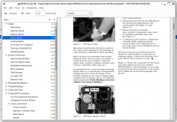
Toyota High Level Order Picker Model 7BPUE15 Repair Service Manual
Toyota High Level Order Picker Model 7BPUE15 Repair Service Manual
Complete service repair manual with Electrical Wiring Diagrams for Toyota High Level Order Picker Model 7BPUE15, with all the technical information to maintain, diagnose, repair, rebuild like professional mechanics.
Toyota High Level Order Picker Model 7BPUE15 workshop service repair manual includes:
* Numbered table of contents easy to use so that you can find the information you need fast.
* Detailed sub-steps expand on repair procedure information
* Numbered instructions guide you through every repair procedure step by step.
* Troubleshooting and electrical service procedures are combined with detailed wiring diagrams for ease of use.
* Notes, cautions and warnings throughout each chapter pinpoint critical information.
* Bold figure number help you quickly match illustrations with instructions.
* Detailed illustrations, drawings and photos guide you through every procedure.
* Enlarged inset helps you identify and examine parts in detail.
PRODUCT DETAILS:
Total Pages: 373 pages
File Format: PDF (Internal Links, Bookmarked, Table of Contents, Searchable, Printable, high quality)
Language: English
00700-CL222-05 - Toyota High Level Order Picker Model 7BPUE15 Service Manual (Serial No. 80,001 and up).pdf
MAIN SECTIONS
R/M: 7BPUE15 SN: 80,001 and up...2
Table of Contents...III
How To Use This Manual...1
Map of the Manual...2
Manual Design...4
Page Revision Page...5
START Page...7
Safety...1
Definitions...2
General Safety...3
Battery Safety...6
Static Safety...9
Jacking Safety...11
Tie-Down for Transport...13
Towing a Disabled Unit...14
Welding Safety...15
Systems Overview...1
Vehicle Specification...2
General System Data...5
Installation Instructions...7
Wire Guidance...8
Cold Storage...9
UL Label "EE"...11
Special Tools...12
Planned Maintenance...1
Maintenance Guidelines...2
Interval 1...3
Interval 2...4
Interval 3...8
Troubleshooting...1
How to Use This Chapter...2
Electrical Troubleshooting Guidelines...3
Shorts to Frame Test...4
Troubleshooting Wiring Problems...8
Switches (General)...10
Electric Motor Tests...11
Battery Discharge Indicator (BDI)...13
Contractors...15
Fuses...15
Hydraulic Troubleshooting Guidelines...16
Definitions...17
Electrical Connector Locator Chart...18
Programmable Maintenance Tool...20
Drive Unit Troubleshooting Guide...25
Troubleshooting Flowcharts...27
Symptom Tables: Hydraulic Functions...31
Symptom Tables: Travel Functions...33
Symptom Tables: Electrical Symptoms...34
Codes and Tests...1
Operator Display Messages...2
Maintenance Mode...4
Traction Power Amplifier Fault Codes...6
Operator Display Fault Codes...15
Component Procedures...1
List of Component Procedures...2
Component Locator Photos...5
Covers and Finish...11
Tractor Covers...11
Operator Console Cover...12
Mast Guard...13
Decals...14
Steering and Controls...15
Operator Display...16
Control Handle...17
Drive and Brake...23
Drive Unit...24
Drive Wheel...25
Brake...27
Electrical Components...31
Battery Procedures...32
Motors (General)...35
Drive Motor...39
Lift Motor...41
Steer Motor...42
Traction Power Amplifier...45
Contactors...46
Contactor Tip Replacement...48
Fuses...50
Circuit Cards (General)...52
Switches (General)...53
Warning Light...55
Hydraulic Components...57
Hydraulic Manifold...58
Hydraulic Reservoir...59
Hydraulic Fluid...60
Solenoid Valves...61
Lift Pump and Motor...62
Lift Pressure Relief Valve Adjustment...63
Bleeding the Hydraulic System...64
Side Cylinder...65
Center Cylinder...69
Flow Control Valve...71
Mast Section...73
Three-Stage Carriage...74
Inner Mast...78
Outer Mast...81
Two-Stage Carriage...82
Two-Stage Mast...84
Mast Bearings...85
Mast Disassembly and Shimming...87
Lift Chains, Three-Stage...91
Lift Chains, Two-Stage...93
Forks...94
Pallet Clamp...95
Load Wheels...96
Skid Pads...97
Wire Guidance...1
System Overview...2
Install Kit Components...3
Set-Up Procedure...9
Codes and Tests...12
Tests...35
General Troubleshooting...37
Troubleshooting in FlashWare...38
Theory of Operation...40
Theory of Operation...1
Battery Plugged In...4
Key Switch (S1) On...10
Closing Deadman Switches...16
Travel...22
Steering...28
Lift/Lower...34
Primary Memory...50
Pinout Matrix...51
Firmware Configuration...1
FlashWare Program...2
Appendix...1
Lubrication Specification Chart...2
Torque Chart - Standard (Ferrous)...3
Torque Chart - Standard (Brass)...4
Torque Chart - Metric...5
Decimal Equivalent Chart...6
Standard/Metric Conversions...8
Electrical Schematics...11
Hydraulic Schematic...18
Index...1


