
Toyota Powered Pallet Trucks Model 7PM18, 7PM20, 7PML20, 7PLL24 Repair Service Manual
Toyota Powered Pallet Trucks Model 7PM18, 7PM20, 7PML20, 7PLL24 Repair Service Manual
Complete service repair manual with Electrical Wiring Diagrams for Toyota Powered Pallet Trucks Model 7PM18, 7PM20, 7PML20, 7PLL24, with all the technical information to maintain, diagnose, repair, rebuild like professional mechanics.
Toyota Powered Pallet Truck 7PM18, 7PM20, 7PML20, 7PLL24 workshop service repair manual includes:
* Numbered table of contents easy to use so that you can find the information you need fast.
* Detailed sub-steps expand on repair procedure information
* Numbered instructions guide you through every repair procedure step by step.
* Troubleshooting and electrical service procedures are combined with detailed wiring diagrams for ease of use.
* Notes, cautions and warnings throughout each chapter pinpoint critical information.
* Bold figure number help you quickly match illustrations with instructions.
* Detailed illustrations, drawings and photos guide you through every procedure.
* Enlarged inset helps you identify and examine parts in detail.
PRODUCT DETAILS:
Total Pages: 518 pages
File Format: PDF (Internal Links, Bookmarked, Table of Contents, Searchable, Printable, high quality)
Language: English
222995-040 - Toyota Powered Pallet Truck 7PM18, 7PM20, 7PML20 Service Manual (Valid from serial number 723984-).pdf
222996-040 - Toyota Powered Pallet Truck 7PLL24 Service Manual (Valid from serial number 723984-).pdf
239389 - Toyota Powered Pallet Truck 7 PM 18, 7 PM 20, 7 PM20N Parts Manual (Valid for machine number 955773 -).pdf
239392 - Toyota Powered Pallet Truck 7 PML20_6, 7 PML 20_8 Parts Manual (Valid for machine number 955773 -).pdf
MAIN SECTIONS
222995-040 - Toyota Powered Pallet Truck 7PM18, 7PM20, 7PML20 Service Manual (Valid from serial number 723984-).....1
1- Table of contents.....3
2- Technical data - M4.....7
3- Introduction Maintenance - P1.....11
3.1 Safety regulations with maintenance work.....11
3.2 Cleaning and washing.....12
3.2.1 External cleaning.....13
3.2.2 Cleaning the motor compartment.....13
3.2.3 Electrical components.....13
3.3 Safe lifting.....13
4- Preventive maintenance - P2.....15
4.1 Maintenance schedule.....15
4.2 Lubrication schedule.....20
5- Oil and grease specifica tion - P3.....21
6- Tools - P4.....23
6.1 Super Seal connectors.....23
6.2 AMP connectors.....24
6.2.1 AMP Connectors, 040 series.....25
6.3 Molex connectors.....25
6.4 Grease guns.....26
6.5 Other tools.....27
7- Fork carriage- 0380.....29
7.1 Maintenance.....29
8- Engine suspension- 0450.....31
8.1 Component parts.....31
8.1.1 Component List.....32
9- Electric drive motor - 1760.....33
9.1 Component parts.....33
9.1.1 Dismantling/assembling of motor from truck.....34
9.1.2 Assembling.....35
9.2 Service/Repairs.....35
9.2.1 Dismantling of motor.....35
9.2.2 Assembling of motor.....36
9.2.3 Cleaning.....36
9.3 Technical data.....37
10- Mechanical drive gear unit - 2550.....39
10.1 Component parts.....40
10.1.1 Technical data.....41
10.2 Leakage from top cover.....42
Dismantling.....42
Assembling.....42
10.3 Changing of the drive shaft’s sealing ring.....42
Dismantling.....42
Assembling.....43
11- Electro magnetic brake - 3370.....45
11.1 Main components.....45
11.2 Maintenance.....46
11.2.1 Exchange of brake disc.....46
12- Electro magnetic brake - 3370.....47
12.1 Main components.....47
12.2 Maintenance.....48
12.2.1 Basic Adjustment of gap.....48
Adjustment:.....48
12.2.2 Exchange of brake disc.....48
13- Steering system - 4000.....49
13.1 Component parts, tiller arm.....49
13.2 Adjustments.....50
13.2.1 Adjusting of brake microswitch.....50
13.3 Tiller arm handle.....51
13.3.1 Dismantling/Assembling.....52
Change from ignition key to keyboard (2).....53
Change from keyboard to ignition key (2).....53
Changing of signal button/switch (9, 10).....53
Changing of lift/lowering button (13).....54
Changing of pushbutton (16).....54
14- Electrical System - 5000.....55
14.1 Electrical components.....55
14.2 Symbol List and Wiring Diagram.....57
14.2.1 Wiring diagram 7PM18, 7PM20, 7PML20-6.....59
14.2.2 Wiring diagram 7PML20-8.....65
14.3 Operating description.....76
14.3.1 Starting truck.....76
14.3.2 Driving speed £ 6 km/h.....76
14.3.3 Braking in neutral mode.....76
14.3.4 Braking in neutral mode on a slope.....76
14.3.5 Braking.....77
14.3.6 Lifting the forks.....77
14.3.7 Lowering the forks.....77
14.3.8 Horn.....77
14.4 Hour meter.....77
14.5 Error codes.....77
14.6 Parameters.....88
14.6.1 Operator parameters.....89
14.6.2 Parameter description.....89
Parameter 1.....89
Parameter 2.....89
Parameter 3.....90
Parameter 4.....90
Parameter 5.....90
14.6.3 Service parameters.....90
14.6.4 Parameter description.....92
Parameter 10.....92
Parameter 14.....92
Parameter 15 - Non-configurable option.....92
Parameter 16 - Configurable option #1.....92
Parameter 17 - Configurable option #2.....92
Parameter 18 - Configurable option #3.....92
Parameter 19 - Configurable option #4.....92
Option parameters.....93
General.....93
Parameter #15 Non-configurable options.....93
Changing non-configurable options.....93
Parameter #16 to 19 configurable optional functions.....94
Changing configurable optional functions.....95
Parameter 20.....99
Parameter 21.....99
Recommendation on parameter setting for freely ventilated batteries.....100
Instructions for verifying parameter setting.....101
Recommendation on parameter setting for valve- controlled batteries (VRLA).....102
Instructions for verifying parameter setting.....103
Parameter 22.....103
Parameter 25.....103
Parameter 28.....103
Parameter 39.....103
Login method and driver parameter access.....104
Expanded keypad - General.....104
Expanded keypad - Programming.....104
Service indication.....106
14.7 Part number.....108
14.8 Transistor panel.....109
14.8.1 General.....109
14.9 Troubleshooting.....110
14.9.1 Error codes and troubleshooting.....110
14.9.2 Reset error.....111
14.9.3 Safety.....111
14.10 Technical specifications - Curtis 1243.....112
15- Hydraulic/Pneumatic - 6000.....113
15.1 General.....113
15.2 Hydraulic chart and list of symbols.....113
15.2.1 List of Symbols.....113
15.3 Adjustments 7PM18.....114
15.3.1 Adjusting the pressure limit valve.....114
15.3.2 Tools.....115
15.4 Adjustments 7PM20.....116
15.4.1 Adjusting the pressure limit valve.....116
15.5 Hydraulic chart and list of symbols.....117
15.5.1 List of Symbols.....117
15.6 Adjusting the pressure limit valve.....118
16- PowerTrak cylinder - 6680.....119
16.1 Component parts.....119
16.2 Dismantling of PowerTrak cylinder.....120
17- Battery charger (Inbuilt) - 8340.....121
17.1 General.....121
17.2 Charging.....121
17.3 Troubleshooting and service.....121
17.4 Technical data.....122
17.5 Charging settings.....122
17.5.1 Freely ventilated batteries.....122
17.5.2 Valve regulated batteries.....123
18- Control/computer equipment - 8700.....125
18.1 General.....125
18.2 Connection.....125
18.3 Layout.....126
18.3.1 Main program screen.....126
18.3.2 Nodes.....126
18.3.3 Icons.....127
18.3.4 Tool buttons and menu bar.....128
18.3.5 Information window.....128
18.3.6 Status bar.....128
18.4 Connection function.....128
18.5 Disconnection function.....129
18.6 Downloading program function.....129
18.6.1 Normal downloading (truck with key).....129
18.6.2 Normal downloading (truck with keypad).....130
18.6.3 Emergency downloading (truck with keypad).....130
18.6.4 Downloading in old versions of logic card.....130
18.6.5 Emergency downloading (truck with keypad).....131
18.7 Truck report function.....132
18.8 Parameters function.....133
18.9 Diagnostics function.....133
18.9.1 Representation of signal colours.....134
18.9.2 “Tiller arm” tab.....134
18.9.3 “Drive Controller” tab (transistor regulator - travel).....135
18.9.4 “Pump controller” tab (transistor regulator - pump).....136
18.9.5 “EPS” steering servo tab.....137
18.10 Other menu functions.....138
18.10.1 Save to file.....138
18.10.2 Download from file.....138
18.10.3 Reset CAN adapter.....138
18.10.4 Delete error code log.....138
18.10.5 Reset hour meter.....138
18.10.6 Read error code log.....138
18.10.7 Adjust date and time.....139
18.10.8 Adjusting the hour meter on older cards.....139
18.10.9 Help.....139
About the TruckCom application.....139
18.10.10 Exit.....139
18.11 Specifications.....139
18.12 Installation.....140
18.12.1 Installation on a PC with Windows® 95/98.....140
18.12.2 Installation on a PC with Windows XP/ 2000.....140
18.12.3 Installation on a PC with Windows NT.....145
18.12.4 In case of communication problems with CAN.....145
18.12.5 To uninstall.....146
222996-040 - Toyota Powered Pallet Truck 7PLL24 Service Manual (Valid from serial number 723984-).....149
1- Contents.....151
2- Technical data - M4.....155
3- Installation and maintenance instructions - P1.....161
3.1 Installation of the new truck.....161
3.1.1 Lifting the truck.....161
3.1.2 Fitting the battery.....163
3.1.3 Start up.....163
3.2 Introduction, maintenance.....165
3.2.1 Safety regulations during maintenance work.....165
3.2.2 Cleaning and washing.....166
3.2.3 Cleaning the exterior.....167
3.2.4 Cleaning the motor compartment.....167
3.2.5 Electrical components.....167
3.3 Safe lifting.....168
4- Preventive maintenance - P2.....169
4.1 Maintenance schedule.....169
4.2 Lubrication chart.....173
5- Oil and grease specification - P3.....175
6- Tools.....177
6.1 Super Seal connectors.....177
6.2 AMP connectors.....178
6.2.1 AMP Connectors, 040 series.....179
6.3 Molex connectors.....179
6.4 Grease guns.....180
6.5 Other tools.....181
7- Fork carriage - 0380.....183
7.1 Component parts.....183
7.2 Dismantling the fork carriage.....185
7.3 Replacing the rollers.....187
8- Engine suspension- 0450.....189
8.1 Component parts.....189
8.1.1 Component List.....190
9- Electric drive motor - 1760.....191
9.1 Component parts.....191
9.2 Removing the motor from the truck.....192
9.3 Refitting the motor in the truck.....193
9.4 Service and repairs.....193
9.4.1 Dismantling N-side.....193
9.4.2 Dismantling D-side.....193
9.4.3 Cleaning.....194
10- Mechanical drive gear unit - 2550.....195
10.1 Component parts.....196
10.1.1 Technical data.....197
10.2 Dismantling/Assembly Leakage from the upper cover.....197
10.3 Replacing the drive shaft gasket.....198
10.3.1 Dismantling.....198
10.3.2 Assembling.....199
10.4 Replacing wheel bolt.....200
11- Electromagnetic brake - 3370.....201
11.1 Component parts.....201
11.2 Dismantling.....202
11.2.1 Inspection.....202
11.3 Assembling.....203
11.4 Manual release of the brake.....203
11.5 Adjustment.....203
11.5.1 Adjusting the play.....203
12- Steering system - 4000.....205
12.1 Component parts, mechanical steering.....205
12.2 Component parts, servo steering (Option).....208
12.2.1 Steering axle, servo steering (Option).....209
12.3 Adjustment, steering.....213
12.3.1 Adjusting the steering servo.....213
12.3.2 Adjusting the steering chain.....213
12.4 Component parts, tiller arm.....214
12.5 Adjustment, tiller arm.....215
12.5.1 Adjusting the brake microswitch.....215
12.6 Tiller arm handle.....216
12.7 Dismantling/Assembly, buttons.....218
Change from ignition key to keyboard (2).....218
Change from keyboard to ignition key (2).....218
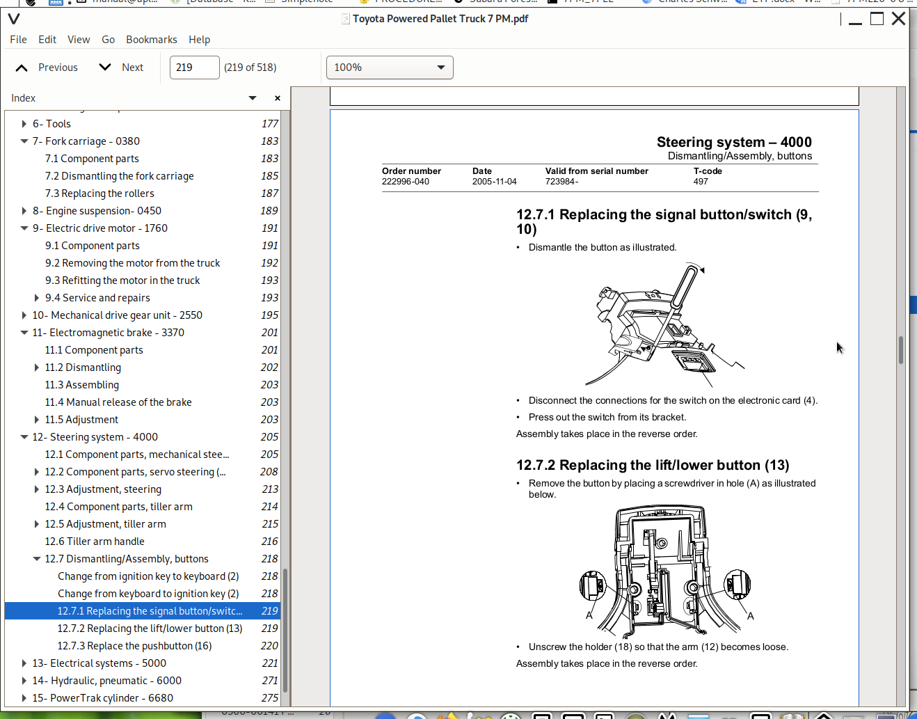
12.7.1 Replacing the signal button/switch (9, 10).....219
12.7.2 Replacing the lift/lower button (13).....219
12.7.3 Replace the pushbutton (16).....220
13- Electrical systems - 5000.....221
13.1 Electrical parts.....221
13.2 Symbol list and electrical diagram.....223
13.2.1 Electrical wiring diagram 1(5).....225
13.2.2 Electrical wiring diagram 2(5).....226
13.2.3 Electrical wiring diagram 3(5).....227
13.2.4 Electrical wiring diagram 4(5).....228
13.2.5 Electrical wiring diagram 5(5).....229
13.2.6 Electrical wiring diagram Servo (Option).....230
13.3 Functional description.....231
13.3.1 Starting the truck.....231
13.3.2 Driving without using platform and gates, speed £ 6 km/h.....231
13.3.3 Driving from platform without using gates,speed £ 6 km/h.....231
13.3.4 Driving from platform and using gates, speed ³ 8 km/h.....231
13.3.5 Neutral speed reduction.....231
13.3.6 Neutral speed reduction on slopes.....232
13.3.7 Braking.....232
13.3.8 Lifting the forks.....232
13.3.9 Lowering the forks.....232
13.3.10 Horn.....232
13.4 Hour meter.....233
13.5 Error codes.....233
13.6 Parameters.....245
13.6.1 Driver parameters.....245
13.6.2 Parameter description.....246
Parameter 1.....246
Parameter 2.....246
Parameter 3.....246
Parameter 4.....246
Parameter 5.....246
13.6.3 Service parameters.....247
13.6.4 Parameter description.....248
Parameter 10.....248
Parameter 14.....248
Parameter 15 - Non-configurable option.....248
Parameter 16 - Configurable option #1.....249
Parameter 17 - Configurable option #2.....249
Parameter 18 - Configurable option #3.....249
Parameter 19 - Configurable option #4.....249
Option parameters.....249
General.....249
Parameter #15 Non-configurable options.....249
Changing non-configurable options.....250
Parameter #16 to 19 configurable optional functions.....251
Changing configurable optional functions.....252
Parameter 20.....256
Parameter 21.....256
Recommendation on parameter setting for freely ventilated batteries.....257
Instructions for verifying parameter setting.....258
Recommendation on parameter setting for valve- controlled batteries (VRLA).....259
Instructions for verifying parameter setting.....260
Parameter 22.....260
Parameter 25.....260
Parameter 28.....260
Parameter 39.....261
Login method and driver parameter access.....261
Expanded keypad - General.....261
Expanded keypad - Programming.....261
Service indication.....263
13.7 Part numbers.....266
13.8 Transistor panel.....266
13.8.1 General.....266
13.9 Diagnostic and troubleshooting.....267
13.9.1 Error codes and troubleshooting.....267
13.9.2 Resetting errors.....268
13.9.3 Safety.....268
13.10 Technical specifications - Curtis 1243.....269
14- Hydraulic, pneumatic - 6000.....271
14.1 General.....271
14.1.1 Hydraulic diagram.....271
14.1.2 Symbol list.....272
14.2 Adjustments.....273
14.2.1 Adjustment of the pressure limit valve.....273
14.3 Cleaning the filter.....274
15- PowerTrak cylinder - 6680.....275
15.1 Component parts.....275
15.2 Dismantling the PowerTrak cylinder.....276
15.2.1 Replacing the gaskets in the PowerTrak cylinder.....277
15.3 Dismantling/assembling the ground pressure springs.....278
15.3.1 Component parts.....278
15.3.2 Dismantling.....279
15.3.3 Assembling.....279
15.3.4 Setting and sealing.....279
15.3.5 Sealing.....280
16- TruckCom.....281
16.1 General.....281
16.2 Connection.....281
16.3 Layout.....282
16.3.1 Main program screen.....282
16.3.2 Nodes.....282
16.3.3 Icons.....283
16.3.4 Tool buttons and menu bar.....283
16.3.5 Information window.....284
16.3.6 Status bar.....284
16.4 Connection function.....284
16.5 Disconnection function.....284
16.6 Downloading program function.....285
16.6.1 Normal downloading (truck with key).....285
16.6.2 Normal downloading (truck with keypad).....285
16.6.3 Emergency downloading (truck with keypad).....286
16.6.4 Emergency downloading (truck with keypad).....286
16.6.5 Downloading in old versions of logic card.....286
16.7 Truck report function.....287
16.8 Parameters function.....288
16.9 Diagnostics function.....288
16.9.1 Representation of signal colours.....289
16.9.2 “Tiller arm” tab.....289
16.9.3 “Drive Controller” tab (transistor regulator driving).....290
16.9.4 “Pump controller” tab (transistor regulator pump).....291
16.9.5 “EPS” (steering servo tab).....292
16.9.6 SEU tab (Spider Extension Unit).....293
16.10 Other menu functions.....293
16.10.1 Save to file.....293
16.10.2 Download from file.....293
16.10.3 Reset CAN adapter.....294
16.10.4 Delete error code log.....294
16.10.5 Reset hour meter.....294
16.10.6 Read error code log.....294
16.10.7 Adjust date and time.....294
16.10.8 Adjusting the hour meter on older cards.....294
16.10.9 Help.....294
About the TruckCom application.....294
16.10.10 Exit.....294
16.11 Specifications.....295
16.12 Installation.....295
16.12.1 Installation on a PC with Windows 95/ 98.....295
16.12.2 Installation on a PC with Windows XP/ 2000.....296
Changes in Windows Control Panel.....298
16.12.3 Installation on a PC with Windows NT.....301
16.12.4 In case of communication problems with CAN.....301
16.12.5 To uninstall.....301
239389 - Toyota Powered Pallet Truck 7 PM 18, 7 PM 20, 7 PM20N Parts Manual (Valid for machine number 955773 -).....305
0000 Chassis.....308
Chassi; Chassis; Châssis.....308
1000 Motors.....308
Motorer; Motoren; Moteurs.....308
2000 Transmission/Drive gear.....308
Kraftöverföring/Drivväxel; Kraftübertragung/Fahrgetriebe; Transmission/Groupe de traction.....308
3000 Brake/Wheel/Caterpillar system.....309
Broms-/Hjul-/Bandsystem; Brems-/Rad-/Bandsystem; Freins/Roues/ Chenilles.....309
4000 Steering system.....309
Styrsystem; Steuer-/Lenksystem; Système de direction.....309
5000 Electrical system.....309
Elektriskt system; Elektroanlage; Système électrique.....309
6000 Hydraulic/pneumatic system.....310
Hydraulik/pneumatik; Hydraulikanlage/Pneumatik; Système hydraulique/pneumatique.....310
9000 Options/attachments.....310
Tillbehör/extrautrustning; Zubehör/Zusatzausrüstung; Equipement supplémentaire/Options.....310
0340-00197 P0013095.....312
0340-00197 Inspection covers [2001-08-24].....312
0380-00374 P0018565.....314
0380-00374 Fork frame (low lifters) [2004-08-26].....315
0380-00558 P0026854.....318
0380-00558 Fork frame (low lifters) [2006-05-19].....319
0390-00112 P0013834.....322
0390-00112 Battery compartment parts [2002-05-15].....323
0390-00121 P0014196.....324
0390-00121 Battery compartment parts [2004-05-13].....325
0390-00298 P0024046.....326
0390-00298 Battery compartment parts [2005-08-11].....326
0400-00089 P0024314.....327
0400-00089 Frame/chassis components [2005-08-11].....327
0400-00096 P0024325.....328
0400-00096 Frame/chassis components [2005-08-11].....328
0820-00193 P0022179.....330
0820-00193 Finger/foot guards [2004-10-01].....331
0850-00219 P0016879.....332
0850-00219 Signs, warnings, decals [2002-09-24].....333
1710-00016 P0011277.....334
1710-00016 Electric pump motor [2004-08-26].....334
1710-00017 P0011299.....335
1710-00017 Electric pump motor [2004-08-26].....335
1760-00101 P0020436.....336
1760-00101 Electric drive motor [2004-08-26].....337
1760-00102 P0020437.....338
1760-00102 Electric drive motor [2004-08-26].....339
2550-00080 P0027237.....340
2550-00080 Mechanical drive gear unit [2006-09-15].....341
3370-00026 P0017735.....344
3370-00026 Electromagnetic parking brake [2006-04-10].....344
3530-00026 P0011304.....345
3530-00026 Drive wheel [2006-08-31].....345
3540-00032 P0011305.....346
3540-00032 Support/castor wheels [2004-08-26].....347
3550-00094 P0016331.....348
3550-00094 Fork/support arm wheels [2004-08-26].....349
3550-00364 P0024114.....350
3550-00364 Fork/support arm wheels [2005-08-11].....351
3570-00061 P0013828.....352
3570-00061 Wheel locating points [2004-08-26].....353
3580-00039 P0021072.....354
3580-00039 Guide rollers/wheels [2004-09-23].....355
4110-00395 P0024158.....356
4110-00395 Steering arm/wheel/lever [2005-08-11].....357
4180-00020 P0013830.....360
4180-00020 Steering bearings, radial bearing [2004-08-26].....361
5160-00079 P0017661.....362
5160-00079 General alarm signals (audible/visual) [2004-08-26].....362
5190-00029 P0012438.....363
5190-00029 Battery cut out connector/contactor [2006-04-10].....363
5190-00039 P0012722.....364
5190-00039 Battery cut out connector/contactor [2004-08-26].....365
5190-00100 P0024053.....366
5190-00100 Battery cut out connector/contactor [2005-08-11].....367
5310-00045 P0014206.....368
5310-00045 Start/stop switch [2004-08-26].....368
5460-00032 P0012482.....369
5460-00032 Transistor panel [2005-04-08].....369
5590-00237 P0024124.....370
5590-00237 Work function harnesses/fuse [2005-08-11].....371
5610-00021 P0016866.....372
5610-00021 Pump contactor [2006-05-17].....372
5820-00181 P0024304.....374
5820-00181 Lift/lowering/reach movement probes/sensors [2005-10-03].....375
5830-00043 P0011357.....376
5830-00043 Safety probes/sensors [2004-08-26].....376
5830-00169 P0024299.....376
5830-00169 Safety probes/sensors [2005-08-11].....376
6100-00059 P0011273.....378
6100-00059 Hydraulic unit [2004-08-26].....379
6100-00189 P0022170.....380
6100-00189 Hydraulic unit [2004-10-01].....381
6120-00165 P0012435.....382
6120-00165 Hydraulic tank lines [2004-08-26].....382
6120-00195 P0016861.....382
6120-00195 Hydraulic tank lines [2004-08-26].....382
6610-00036 P0011252.....383
6610-00036 Main lift cylinders [2006-01-19].....383
9380-00004 P0017729.....384
9380-00004 Charger attachment [2006-04-10].....384
9380-00005 P0017731.....385
9380-00005 Charger attachment [2006-04-10].....385
9380-00011 P0020457.....385
9380-00011 Charger attachment [2006-04-10].....385
9400-00077 P0015416.....386
9400-00077 Extra electrical equipment [2005-05-04].....387
9400-00078 P0015420.....388
9400-00078 Extra electrical equipment [2006-04-10].....389
9400-00194 P0026365.....390
9400-00194 Extra electrical equipment [2006-03-02].....391
9400-00195 P0026366.....392
9400-00195 Extra electrical equipment [2006-03-02].....393
9400-00196 P0026367.....394
9400-00196 Extra electrical equipment [2006-03-02].....395
9420-00015 P0012396.....396
9420-00015 Truck log device, code locking device [2006-04-10].....396
9420-00065 P0022181.....398
9420-00065 Truck log device, code locking device [2004-10-01].....399
9420-00098 P0026077.....400
9420-00098 Truck log device, code locking device [2006-04-10].....400
9500-00208 P0012488.....402
9500-00208 Other extra equipment [2005-12-14].....403
9500-00219 P0012481.....404
9500-00219 Other extra equipment [2004-08-26].....404
9500-00524 P0018662.....405
9500-00524 Other extra equipment [2004-08-26].....405
9500-00712 P0024329.....406
9500-00712 Other extra equipment [2006-04-10].....406
9550-00014 P0012487.....408
9550-00014 Battery changing equipment [2004-08-26].....409
239392 - Toyota Powered Pallet Truck 7 PML20_6, 7 PML 20_8 Parts Manual (Valid for machine number 955773 -).....410
0000 Chassis.....413
Chassi; Chassis; Châssis.....413
1000 Motors.....413
Motorer; Motoren; Moteurs.....413
2000 Transmission/Drive gear.....414
Kraftöverföring/Drivväxel; Kraftübertragung/Fahrgetriebe; Transmission/Groupe de traction.....414
3000 Brake/Wheel/Caterpillar system.....414
Broms-/Hjul-/Bandsystem; Brems-/Rad-/Bandsystem; Freins/Roues/ Chenilles.....414
4000 Steering system.....414
Styrsystem; Steuer-/Lenksystem; Système de direction.....414
5000 Electrical system.....414
Elektriskt system; Elektroanlage; Système électrique.....414
6000 Hydraulic/pneumatic system.....415
Hydraulik/pneumatik; Hydraulikanlage/Pneumatik; Système hydraulique/pneumatique.....415
9000 Options/attachments.....416
Tillbehör/extrautrustning; Zubehör/Zusatzausrüstung; Equipement supplémentaire/Options.....416
0340-00476 P0024035.....417
0340-00476 Inspection covers [2005-08-11].....417
0380-00497 P0024103.....419
0380-00497 Fork frame (low lifters) [2005-08-11].....420
0390-00112 P0013834.....422
0390-00112 Battery compartment parts [2002-05-15].....424
0390-00121 P0014196.....425
0390-00121 Battery compartment parts [2004-05-13].....426
0390-00298 P0024046.....427
0390-00298 Battery compartment parts [2005-08-11].....427
0400-00095 P0024323.....429
0400-00095 Frame/chassis components [2005-08-11].....430
0450-00084 P0024338.....431
0450-00084 Motor fixing points [2005-08-11].....432
0560-00139 P0024305.....433
0560-00139 Platform incl. fixing points [2005-08-11].....434
0560-00141 P0024307.....435
0560-00141 Platform incl. fixing points [2005-08-11].....436
0820-00210 P0024023.....437
0820-00210 Finger/foot guards [2005-08-11].....437
0840-00058 P0013150.....438
0840-00058 Driver protection [2001-08-24].....438
0840-00113 P0021125.....439
0840-00113 Driver protection [2004-08-23].....439
0840-00142 P0024031.....441
0840-00142 Driver protection [2005-08-11].....442
0850-00226 P0016905.....443
0850-00226 Signs, warnings, decals [2006-05-10].....444
1710-00017 P0011299.....445
1710-00017 Electric pump motor [2004-08-26].....445
1760-00103 P0020439.....447
1760-00103 Electric drive motor [2004-08-24].....448
1760-00104 P0020440.....449
1760-00104 Electric drive motor [2004-08-24].....450
2550-00081 P0027238.....451
2550-00081 Mechanical drive gear unit [2006-09-15].....452
3370-00011 P0011271.....455
3370-00011 Electromagnetic parking brake [2004-08-24].....456
3370-00027 P0017736.....457
3370-00027 Electromagnetic parking brake [2004-08-24].....457
3530-00102 P0021057.....458
3530-00102 Drive wheel [2004-08-24].....458
3540-00040 P0012388.....459
3540-00040 Support/castor wheels [2004-08-24].....460
3550-00363 P0024106.....461
3550-00363 Fork/support arm wheels [2005-09-28].....462
3580-00039 P0021072.....463
3580-00039 Guide rollers/wheels [2004-09-23].....464
4110-00397 P0024195.....465
4110-00397 Steering arm/wheel/lever [2005-08-11].....466
4180-00019 P0013829.....469
4180-00019 Steering bearings, radial bearing [2006-04-10].....469
5160-00079 P0017661.....471
5160-00079 General alarm signals (audible/visual) [2004-08-26].....471
5190-00029 P0012438.....472
5190-00029 Battery cut out connector/contactor [2006-04-10].....472
5190-00039 P0012722.....473
5190-00039 Battery cut out connector/contactor [2004-08-26].....474
5190-00100 P0024053.....475
5190-00100 Battery cut out connector/contactor [2005-08-11].....476
5310-00060 P0017055.....477
5310-00060 Start/stop switch [2004-08-24].....477
5460-00040 P0013153.....478
5460-00040 Transistor panel [2004-09-09].....478
5590-00236 P0024123.....479
5590-00236 Work function harnesses/fuse [2005-08-11].....479
5590-00241 P0024301.....481
5590-00241 Work function harnesses/fuse [2005-08-11].....482
5610-00021 P0016866.....483
5610-00021 Pump contactor [2006-05-17].....483
5830-00067 P0012445.....484
5830-00067 Safety probes/sensors [2006-04-10].....484
5830-00148 P0022182.....484
5830-00148 Safety probes/sensors [2005-08-12].....484
5830-00170 P0024300.....485
5830-00170 Safety probes/sensors [2005-08-11].....485
5830-00171 P0024309.....487
5830-00171 Safety probes/sensors [2005-08-11].....488
5830-00172 P0024310.....489
5830-00172 Safety probes/sensors [2005-08-11].....489
6100-00190 P0022214.....491
6100-00190 Hydraulic unit [2004-10-01].....492
6120-00194 P0016859.....493
6120-00194 Hydraulic tank lines [2004-08-24].....493
6610-00221 P0027243.....495
6610-00221 Main lift cylinders [2006-09-15].....496
6680-00034 P0018043.....497
6680-00034 Powertrak cylinder [2004-08-24].....498
9380-00004 P0017729.....499
9380-00004 Charger attachment [2006-04-10].....499
9380-00005 P0017731.....500
9380-00005 Charger attachment [2006-04-10].....500
9380-00011 P0020457.....500
9380-00011 Charger attachment [2006-04-10].....500
9400-00198 P0026371.....501
9400-00198 Extra electrical equipment [2006-03-02].....502
9400-00199 P0026372.....503
9400-00199 Extra electrical equipment [2006-03-02].....504
9400-00200 P0026373.....505
9400-00200 Extra electrical equipment [2006-03-02].....506
9420-00015 P0012396.....507
9420-00015 Truck log device, code locking device [2006-04-10].....507
9420-00092 P0024042.....509
9420-00092 Truck log device, code locking device [2005-08-11].....510
9420-00098 P0026077.....511
9420-00098 Truck log device, code locking device [2006-04-10].....511
9500-00208 P0012488.....512
9500-00208 Other extra equipment [2005-12-14].....512
9500-00219 P0012481.....513
9500-00219 Other extra equipment [2004-08-26].....513
9500-00524 P0018662.....514
9500-00524 Other extra equipment [2004-08-26].....514
9500-00712 P0024329.....515
9500-00712 Other extra equipment [2006-04-10].....515
9550-00013 P0012468.....517
9550-00013 Battery changing equipment [2006-04-13].....518
![]()