
Toyota Powered Pallet Stacker 7SM/7SLL Series Repair Service Manual
Complete service repair manual with Electrical Wiring Diagrams for Toyota Powered Pallet Stacker Models 7SM08F, 7SM10, 7SM12, 7SM12F, 7SM12S, 7SM16D, 7SLL12.5, 7SLL16, 7SLL13.5S, 7SLL12.5F, 7SLL16F, with all the technical information to maintain, diagnose, repair, rebuild like professional mechanics.
Toyota Powered Pallet Stacker 7SM/7SLL Series workshop service repair manual includes:
* Numbered table of contents easy to use so that you can find the information you need fast.
* Detailed sub-steps expand on repair procedure information
* Numbered instructions guide you through every repair procedure step by step.
* Troubleshooting and electrical service procedures are combined with detailed wiring diagrams for ease of use.
* Notes, cautions and warnings throughout each chapter pinpoint critical information.
* Bold figure number help you quickly match illustrations with instructions.
* Detailed illustrations, drawings and photos guide you through every procedure.
* Enlarged inset helps you identify and examine parts in detail.
PRODUCT DETAILS:
Total Pages: 1,460 pages
File Format: PDF (Internal Links, Bookmarked, Table of Contents, Searchable, Printable, high quality)
Language: English
202184-040 - Toyota Powered Pallet Stacker 7SM10/12, 7SM12S Series Service Manual.pdf
202185-040 - Toyota Powered Pallet Stacker 7SM Series Service Manual.pdf
202187-040 - Toyota Powered Pallet Stacker 7SM12F, 7SM16D Service Manual.pdf
226306-040 (2005) - Toyota Powered Pallet Stacker 7SM10, 7SM12, 7SM12S Service Manual.pdf
226306-040 (2006) - Toyota Powered Pallet Stacker 7SM10, 7SM12, 7SM12S Service Manual.pdf
226307-040 - Toyota Powered Pallet Stacker 7SM12F, 7SM16D Service Manual.pdf
229102-040 - Toyota Powered Pallet Stacker 7SM12F, 7SM16D Service Manual.pdf
229735-040 (2005) - Toyota Powered Pallet Stacker 7SM08F Service Manual (Valid from serial number 904519-).pdf
229735-040 (2006) - Toyota Powered Pallet Stacker 7SM08F Service Manual (Valid from serial number 904519-).pdf
230087-040 - Toyota Powered Pallet Stacker 7SLL12.5, 7SLL16, 7SLL13.5S, 7SLL12.5F, 7SLL16F Service Manual.pdf
MAIN SECTIONS
202184-040 - Toyota Powered Pallet Stacker 7SM1012, 7SM12S Series Service Manual...1
Contents...3
Technical data 7...3
Introduction Maintenance 11...3
1 Safety regulations with maintenance work 11...3
2 Cleaning and washing 13...3
3 Safe lifting 14...3
Preventive maintenance 15...3
1 Maintenance schedule 15...3
2 Lubrication schedule 20...3
Oil and grease specification 21...3
Tools 23...3
1 Super Seal connectors 23...3
Support arm chassis 27...3
1 General 27...3
2 Main components 28...3
3 Maintenance 28...3
4 Adjustment of the support arm width 29...3
5 Exchange of support arms 30...3
Electric drive motor 31...3
1 Component parts 31...3
2. Service/Repairs 33...3
3 Technical data 35...3
Drive unit/gear 37...4
1 Component parts 38...4
2 Leakage from top cover 40...4
3 Changing of the drive shaft’s sealing ring 40...4
Electro magnetic brake 43...4
1 Main components of the brake 43...4
2 Maintenance 44...4
Steering 47...4
1 Component parts, tiller arm 47...4
2 Adjustments 48...4
3 Tiller arm handle 49...4
Electrical systems 55...4
1 Electrical parts 55...4
2 List of symbols and electrical wiring diagram 57...4
3 Functional description 64...4
4 Hour meter 66...4
5 Fault codes 66...4
6 Parameters 71...4
7 Part numbers 80...4
8 Transistor panel 81...4
9 Diagnostic and troubleshooting 82...4
10 Technical specifications – Curtis 1243 84...4
Hydraulic system 85...4
1 Hydraulic diagram and components 85...4
Control/computer equipment 89...5
1 General 89...5
2 Connection 89...5
3 Layout 90...5
4 Function 92...5
5 Specifications 100...5
Battery charger (Inbuilt) 101...5
1 General 101...5
2 Charging 101...5
3 Troubleshooting and service 102...5
4 Technical data 102...5
5 Charging settings 103...5
Technical data...7
Model...7
7SM10...7
7SM12...7
7SM12S...7
Introduction Maintenance...11
1 Safety regulations with maintenance work...11
WARNING!...11
WARNING!...12
WARNING!...12
NOTE!...12
CAUTION!...12
2 Cleaning and washing...13
NOTE!...13
2.1 External cleaning...13
NOTE!...13
2.2 Cleaning the motor compartment...13
NOTE!...13
2.3 Electrical components...13
NOTE!...13
3 Safe lifting...14
WARNING!...14
Preventive maintenance...15
1 Maintenance schedule...15
Pos. No...15
Work to carry out...15
2 Lubrication schedule...20
Pos no...20
Service point...20
Interval/Running hours...20
Lubricant...20
Oil and grease specification...21
Lubticant...21
Specification...21
Application area...21
Tools...23
1 Super Seal connectors...23
Figure...23
Number...23
Application...23
1.1 AMP connectors...24
Figure...24
Number...24
Application...24
1.2 Other tools...25
Figure...25
Number...25
Application...25
Support arm chassis...27
1 General...27
2 Main components...28
3 Maintenance...28
4 Adjustment of the support arm width...29
Warning!...29
5 Exchange of support arms...30
Electric drive motor...31
1 Component parts...31
Pos...31
Description...31
Note...31
1.1 Dismantling of motor from truck...32
1.2 Assembling...32
2. Service/Repairs...33
2.1 Dismantling of motor...33
2.2 Assembling of motor...34
2.3 Cleaning...34
3 Technical data...35
Drive unit/gear...37
1 Component parts...38
Pos...38
Description...38
Note...38
1.1 Technical data...39
Type of truck...39
7SM10/12, 7SM12S...39
2 Leakage from top cover...40
3 Changing of the drive shaft’s sealing ring...40
3.1 Dismantling...40
3.2 Assembling...41
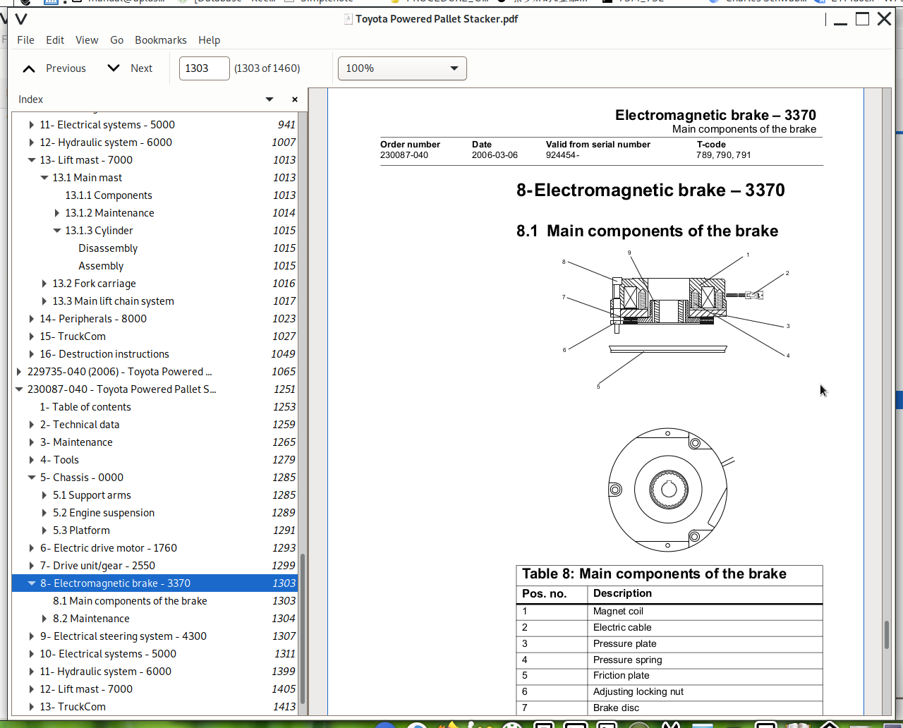
Electro magnetic brake...43
1 Main components of the brake...43
2 Maintenance...44
2.1 Basic Adjustment of gap...44
2.2 Exchange of brake disc...45
Steering...47
1 Component parts, tiller arm...47
Pos...48
Description...48
Note...48
2 Adjustments...48
2.1 Adjusting of brake microswitch...48
3 Tiller arm handle...49
Pos...49
Description...49
Note...49
3.1 Dismantling/Assembling...51
NOTE!...51
Change from ignition key to keyboard (2)...51
Change from keyboard to ignition key (2)...51
Changing of signal button/switch (9, 10)...52
Changing of lift/lowering button (13)...53
Changing of pushbutton (16)...53
Electrical systems...55
1 Electrical parts...55
2 List of symbols and electrical wiring diagram...57
Symbol...57
Description...57
Function...57
Notes...57
2.1. Elschema 1 (5)...59
2.2. Elschema 2(5)...60
2.3. Elschema 3(5)...61
2.4. Elschema 4(5)...62
2.5. Elschema 5(5)...63
3 Functional description...64
3.1 Starting the truck...64
3.2 Driving...64
3.3 Neutral speed reduction...64
3.4 Picture 3...64
3.5 Neutral speed reduction on slopes...65
3.6 Braking...65
3.7 Lifting the forks...65
3.8 Lowering the forks...65
3.9 Horn...65
4 Hour meter...66
5 Fault codes...66
Code...67
C19...67
Code...67
C20...67
Code...67
C28...67
Code...67
C29...67
Code...67
C41...67
Code...68
C42...68
Code...68
C43...68
Code...68
E101...68
Code...68
E104...68
Code...68
E106...68
Code...69
E107...69
Code...69
E108...69
Kod...69
E110...69
Code...69
E140...69
Code...69
E141...69
Code...69
E150...69
Code...70
E151...70
Code...70
E157...70
Code...70
E159...70
Code...70
E160...70
Code...70
E200...70
Code...70
E201...70
Code...71
E202...71
Code...71
E214...71
6 Parameters...71
NOTE !...71
6.1 Driver parameters...72
Parameter...72
Name...72
Unit...72
Min...72
Max...72
Step...72
Std...72
Description...72
6.2 Service parameters...73
Parameter...73
Name...73
Unit...73
Min...73
Max...73
Step...73
Std...73
Description...73
6.3 Parameter description...74
Parameter 1...74
Parameter 2...74
Parameter 3...74
Parameter 4...74
Parameter 5...74
Parameter 10...74
Parameter 14...74
Parameter 20...75
Parameter 21...75
Value...76
Function...76
Battery (Ah)...76
WARNING !...76
Parameter 25...76
Parameter 28...77
Parameter 39...77
Service display...77
Flashing symbol...78
Displayed data...78
Segment...78
Function...78
Segment...79
Function...79
Segment...79
Function...79
Segment...80
Function...80
7 Part numbers...80
8 Transistor panel...81
8.1 General...81
9 Diagnostic and troubleshooting...82
9.1 Error codes and troubleshooting...82
STATUS LED...82
Handheld terminal display...82
Explanation...82
Possible cause...82
9.2 Resetting errors...83
Error...83
Reset when...83
9.3 Safety...83
WARNING!...83
10 Technical specifications – Curtis 1243...84
Value...84
Unit...84
Explanation...84
Hydraulic system...85
1 Hydraulic diagram and components...85
1.1 Main components...86
Pos No...86
Description...86
Remark...86
1.2 Description...86
1.2.1 Lift...86
1.2.2 Lowering...86
1.2.3 Operating pressure...86
1.2.4 Relief valve...86
1.2.5. Pressure switch...87
Control/computer equipment...89
1 General...89
2 Connection...89
3 Layout...90
3.1 Main window...90
3.2 Nodes...90
3.2.1 Icons...91
Icon...91
Description...91
3.3 Tool buttons...91
3.4 Information window...92
3.5 Status bar...92
4 Function...92
4.1 Connection...92
4.2 Disconnection...92
4.3 Downloading program...93
4.3.1 Normal downloading...93
4.3.2 Downloading in old versions of logic card...93
4.3.3 Emergency downloading...94
NOTE!...94
4.4 Truck report...95
4.5 Parameters...96
NOTE!...96
4.6 Diagnostics...97
NOTE!...97
4.6.1 Analogue...97
4.6.2 Temperature...98
NOTE!...98
4.6.3 Digital...98
4.7 Other functions...99
4.7.1 Save to file...99
4.7.2 Download from file...99
4.7.3 Reset CAN adapter...99
4.7.4 Delete error code log...99
4.7.5 Reset hour meter...99
4.7.6 Read error code log...99
4.7.7 Adjust date and time...99
NOTE!...99
4.7.8 Adjusting the hour meter on older cards...99
4.8 Help...100
4.8.1 About TruckCom...100
4.9 Exit...100
5 Specifications...100
5.1 CAN interface...100
5.2 Installation...100
5.3 To uninstall...100
Battery charger (Inbuilt)...101
1 General...101
2 Charging...101
3 Troubleshooting and service...102
4 Technical data...102
5 Charging settings...103
5.1 Freely ventilated batteries...103
Switch...103
Batterysize...103
Output current...103
I2 current...103
Max current maintenance...103
5.2 Valve regulated batteries...103
Switch...103
Batterysize...103
Output current...103
I2 current...103
Max current maintenance...103
202185-040 - Toyota Powered Pallet Stacker 7SM Series Service Manual...105
Contents...107
Electrical systems 5...107
1 Electrical diagram 7SM10/12, 7SM12S 1(5) 5...107
2 Electrical diagram 7SM12F, 7SM16D 1(5) 10...107
3 Component identification 15...107
4 Error codes and troubleshooting 19...107
5 Fault codes 20...107
6 Parameters 22...107
7 Part numbers 27...107
Hydraulic diagram and components 29...107
1 Main components 7SM10/12/12S 29...107
2 Main components 7SM12F/16D 30...107
Tightening torque 33...107
1 Basic Adjustment of gap 34...107
Oil and grease specification 35...107
Preventive maintenance 37...107
1 Maintenance schedule 37...107
2 Lubrication schedule 42...107
Lifting points 43...107
Electrical systems...109
1 Electrical diagram 7SM10/12, 7SM12S 1(5)...109
Electrical diagram 7SM10/12, 7SM12S 2(5)...110
Electrical diagram 7SM10/12, 7SM12S 3(5)...111
Electrical diagram 7SM10/12, 7SM12S 4(5)...112
Electrical diagram 7SM10/12, 7SM12S 5(5)...113
2 Electrical diagram 7SM12F, 7SM16D 1(5)...114
Electrical diagram 7SM12F, 7SM16D 2(5)...115
Electrical diagram 7SM12F, 7SM16D 3(5)...116
Electrical diagram 7SM12F, 7SM16D 4(5)...117
Electrical diagram 7SM12F, 7SM16D 5(5)...118
3 Component identification...119
3.1 List of symbols...121
Symbol...121
Description...121
Function...121
Notes...121
4 Error codes and troubleshooting...123
WARNING!...123
STATUS LED...123
Handheld terminal display...123
Explanation...123
Possible cause...123
5 Fault codes...124
Code...124
Description...124
Possible fault reason...124
6 Parameters...126
NOTE !...126
6.1 Driver parameters...127
Parameter...127
Name...127
Unit...127
Min...127
Max...127
Step...127
Std...127
Description...127
6.2 Service parameters...128
Parameter...128
Name...128
Unit...128
Min...128
Max...128
Step...128
Std...128
Description...128
Parameter 21...128
Service display...129
Flashing symbol...129
Displayed data...129
Segment...129
Function...129
Segment...130
Function...130
Segment...130
Function...130
Segment...131
Function...131
7 Part numbers...131
Hydraulic diagram and components...133
1 Main components 7SM10/12/12S...133
Pos No...133
Description...133
Remark...133
2 Main components 7SM12F/16D...134
Pos No...134
Description...134
Remark...134
2.1 Description...135
2.1.1 Lift...135
2.1.2 Lowering...135
2.1.3 Operating pressure...135
2.1.4 Relief valve...135
2.1.5. Pressure switch...136
Tightening torque...137
1 Basic Adjustment of gap...138
Oil and grease specification...139
Lubticant...139
Specification...139
Application area...139
Preventive maintenance...141
1 Maintenance schedule...141
Pos. No...141
Work to carry out...141
2 Lubrication schedule...146
Pos no...146
Service point...146
Interval/Running hours...146
Lubricant...146
Lifting points...147
WARNING!...147
WARNING!...147
202187-040 - Toyota Powered Pallet Stacker 7SM12F, 7SM16D Service Manual...149
Contents...151
Technical data 5...151
Introduction Maintenance 9...151
Preventive maintenance 13...151
Oil and grease specification 21...151
Tools 23...151
Electric drive motor 27...151
Drive unit/gear 33...151
Electro magnetic brake 39...151
Steering 43...152
Electrical systems 51...152
Hydraulic system 81...152
Control/computer equipment 85...152
Battery charger (Inbuilt) 99...152
Technical data...153
Model...153
7SM12F...153
7SM16D...153
Introduction Maintenance...157
1 Safety regulations with maintenance work...157
WARNING!...157
WARNING!...158
WARNING!...158
NOTE!...158
CAUTION!...158
2 Cleaning and washing...159
NOTE!...159
2.1 External cleaning...159
NOTE!...159
2.2 Cleaning the motor compartment...159
NOTE!...159
2.3 Electrical components...160
NOTE!...160
3 Safe lifting...160
WARNING!...160
Preventive maintenance...161
1 Maintenance schedule...161
Pos. No...161
Work to carry out...161
2 Lubrication schedule...166
Pos no...166
Service point...166
Interval/Running hours...166
Lubricant...166
Oil and grease specification...169
Lubticant...169
Specification...169
Application area...169
Tools...171
1 Super Seal connectors...171
Figure...171
Number...171
Application...171
1.1 AMP connectors...172
Figure...172
Number...172
Application...172
1.2 Other tools...173
Figure...173
Number...173
Application...173
Electric drive motor...175
1 Component parts...175
Pos...175
Description...175
Note...175
1.1 Dismantling of motor from truck...176
1.2 Assembling...177
2 Service/Repairs...178
2.1 Dismantling of motor...178
2.2 Assembling of motor...179
2.3 Cleaning...179
3 Technical data...180
Type of machine...180
7SM12F, 7SM16D...180
Drive unit/gear...181
1 Component parts...182
Pos...182
Description...182
Note...182
1.1 Technical data...183
Type of truck...183
7SM12F, 7SM16D...183
2 Leakage from top cover...184
3 Changing of the drive shaft’s sealing ring...184
3.1 Dismantling...184
3.2 Assembling...185
Electro magnetic brake...187
1 Main components of the brake...187
2 Maintenance...188
2.1 Basic Adjustment of gap...188
2.2 Exchange of brake disc...189
Steering...191
1 Component parts, tiller arm...191
Pos...191
Description...191
Note...191
2 Adjustments...192
2.1 Adjusting of brake microswitch...192
3 Tiller arm handle...193
Pos...193
Description...193
Note...193
3.1 Dismantling/Assembling...195
NOTE!...195
Change from ignition key to keyboard (2)...195
Change from keyboard to ignition key (2)...195
Changing of signal button/switch (9, 10)...196
Changing of lift/lowering button (13)...197
Changing of pushbutton (16)...197
Electrical systems...199
1 Component identification...199
2 List of symbols and electrical wiring diagram...201
Symbol...201
Description...201
Function...201
Notes...201
2.1 Electrical diagram 1(5)...203
2.2 Electrical diagram 2(5)...204
2.3 Electrical diagram 3(5)...205
2.4 Electrical diagram 4(5)...206
2.5 Electrical diagram 5(5)...207
3 Functional description...208
3.1 Starting the truck...208
3.2 Driving...208
3.3 Neutral speed reduction...208
3.4 Picture 3...208
3.5 Neutral speed reduction on slopes...209
3.6 Braking...209
3.7 Lifting the forks...209
3.8 Lifting the support arms...209
3.9 Lowering the forks...209
3.10 Lowering the support arms...209
3.11 Horn...209
4 Hour meter...210
5 Fault codes...210
Code...211
C19...211
Code...211
C20...211
Code...211
C28...211
Code...211
C29...211
Code...211
C41...211
Code...212
C42...212
Code...212
C43...212
Code...212
E101...212
Code...212
E104...212
Code...212
E106...212
Code...213
E107...213
Code...213
E108...213
Code...213
E110...213
Code...213
E140...213
Code...213
E141...213
Code...213
E150...213
Code...214
E151...214
Code...214
E157...214
Code...214
E159...214
Code...214
E160...214
Code...214
E200...214
Code...214
E201...214
Code...215
E202...215
Code...215
E214...215
6 Parameters...215
NOTE !...215
6.1 Driver parameters...216
Parameter...216
Name...216
Unit...216
Min...216
Max...216
Step...216
Std...216
Description...216
6.2 Service parameters...217
Parameter...217
Name...217
Unit...217
Min...217
Max...217
Step...217
Std...217
Description...217
6.3 Parameter description...218
Parameter 1...218
Parameter 2...218
Parameter 3...218
Parameter 4...218
Parameter 5...218
Parameter 10...218
Parameter 14...218
Parameter 20...219
Parameter 21...219
Value...220
Function...220
Battery (Ah)...220
WARNING !...220
Parameter 25...220
Parameter 28...221
Parameter 39...221
Service display...221
Flashing symbol...222
Displayed data...222
Segment...222
Function...222
Segment...223
Function...223
Segment...223
Function...223
Segment...224
Function...224
7 Part numbers...224
8 Transistor panel...225
8.1 General...225
9 Diagnostic and troubleshooting...226
9.1 Error codes and troubleshooting...226
STATUS LED...226
Handheld terminal display...226
Explanation...226
Possible cause...226
9.2 Resetting errors...227
Error...227
Reset when...227
9.3 Safety...227
WARNING!...227
10 Technical specifications – Curtis 1243...228
Value...228
Unit...228
Explanation...228
Hydraulic system...229
1 Hydraulic diagram and components...229
1.1 Main components...229
Pos No...229
Description...229
Remark...229
1.2 Description...230
1.2.1 Lift...230
1.2.2 Lowering...230
1.2.3 Operating pressure...230
1.2.4 Relief valve...230
1.2.5. Pressure switch...231
Control/computer equipment...233
1 General...233
2 Connection...233
3 Layout...234
3.1 Main window...234
3.2 Nodes...234
3.2.1 Icons...235
Icon...235
Description...235
3.3 Tool buttons...235
3.4 Information window...236
3.5 Status bar...236
4 Function...236
4.1 Connection...236
4.2 Disconnection...237
4.3 Downloading program...237
4.3.1 Normal downloading...238
4.3.2 Downloading in old versions of logic card...238
4.3.3 Emergency downloading...238
NOTE!...238
4.4 Truck report...239
4.5 Parameters...240
NOTE!...240
4.6 Diagnostics...241
NOTE!...241
4.6.1 Analogue...241
4.6.2 Temperature...242
NOTE!...242
4.6.3 Digital...242
4.7 Other functions...243
4.7.1 Save to file...243
4.7.2 Download from file...243
4.7.3 Reset CAN adapter...243
4.7.4 Delete error code log...243
4.7.5 Reset hour meter...243
4.7.6 Read error code log...243
4.7.7 Adjust date and time...243
NOTE!...243
4.7.8 Adjusting the hour meter on older cards...244
4.8 Help...244
4.8.1 About TruckCom...244
4.9 Exit...244
5 Specifications...244
5.1 CAN interface...244
5.2 Installation...245
5.3 To uninstall...245
Battery charger (Inbuilt)...247
1 General...247
2 Charging...247
3 Troubleshooting and service...248
4 Technical data...248
5 Charging settings...249
5.1 Freely ventilated batteries...249
Switch...249
Batterysize...249
Output current...249
I2 current...249
Max current maintenance...249
5.2 Valve regulated batteries...249
Switch...249
Batterysize...249
Output current...249
I2 current...249
Max current maintenance...249
226306-040 (2005) - Toyota Powered Pallet Stacker 7SM10, 7SM12, 7SM12S Service Manual...251
1- Table of contents...253
2- Technical data - M4...259
3- Introduction Maintenance - P1...263
3.1 Safety regulations with maintenance work...263
3.2 Cleaning and washing...264
3.2.1 External cleaning...265
3.2.2 Cleaning the motor compartment...265
3.2.3 Electrical components...265
3.3 Safe lifting...266
4- Preventive maintenance - P2...267
4.1 Maintenance schedule...267
4.2 Lubrication schedule...272
5- Oil and grease specification - P3...273
6- Tools - P4...275
6.1 Super Seal connectors...275
6.2 AMP connectors...276
6.2.1 AMP Connectors, 040 series...277
6.3 Molex connectors...277
![]()