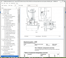
Toyota Powered Pallet Stacker SP10, SP10S Repair Service Manual
Complete service repair manual with Electrical Wiring Diagrams for Toyota Powered Pallet Stacker SP10, SP10S, with all the technical information to maintain, diagnose, repair, rebuild like professional mechanics.
Toyota Powered Pallet Stacker SP10, SP10S workshop service repair manual includes:
* Numbered table of contents easy to use so that you can find the information you need fast.
* Detailed sub-steps expand on repair procedure information
* Numbered instructions guide you through every repair procedure step by step.
* Troubleshooting and electrical service procedures are combined with detailed wiring diagrams for ease of use.
* Notes, cautions and warnings throughout each chapter pinpoint critical information.
* Bold figure number help you quickly match illustrations with instructions.
* Detailed illustrations, drawings and photos guide you through every procedure.
* Enlarged inset helps you identify and examine parts in detail.
235568-040 (2006-04-10) - Toyota Powered Pallet Stacker SP10, SP10S Service Manual (Valid from serial number: 904526-).pdf
PRODUCT DETAILS:
Total Pages: 118 pages
File Format: PDF (Internal Links, Bookmarked, Table of Contents, Searchable, Printable, high quality)
Language: English
TABLE OF CONTENTS
1- Table of contents.....3
2- Technical data.....7
2.1 General tightening torques.....10
3- Maintenance.....11
3.1 Safety regulations with maintenance work.....11
3.2 Cleaning and washing.....13
3.2.1 External cleaning.....13
3.2.2 Cleaning the motor compartment.....13
3.2.3 Electrical components.....13
3.3 Safe lifting.....14
3.4 Lifting the truck.....15
3.5 Placing the truck on its side.....16
3.6 Maintenance Schedule.....17
3.7 Lubrication chart.....21
4- Oil and grease specification.....23
5- Tools.....25
5.1 Super Seal connectors.....25
5.2 AMP connectors.....26
5.2.1 AMP Connectors, 040 series.....27
5.3 Molex connectors.....27
5.4 Grease guns.....28
5.5 Other tools.....29
6- Chassis - 0000.....31
6.1 Support arms SP10.....31
6.1.1 Placement of supportarms.....32
6.2 Support arms SP10S.....33
6.2.1 General.....33
6.2.2 Main Components.....33
6.2.3 Maintenance.....34
6.2.4 Adjusting the support arm width.....34
6.2.5 Replacing support arms.....35
7- Drive unit/drive gear - 2000.....37
7.1 Component parts.....37
7.2 Service and repairs.....38
7.2.1 Dismantling the motor from the truck.....38
7.2.2 Inspection/replacement of the carbon brushes.....38
7.2.3 Replacing the drive gear.....39
7.2.4 Cleaning.....39
7.2.5 Brakes, Maintenance.....40
7.2.6 Replacing the brake disc.....40
8- Wheel system - 3000.....41
8.1 Swivel wheel suspension.....41
8.1.1 Components.....41
8.1.2 Lubricating the nipples.....41
8.1.3 Adjusting the swivel wheel pressure.....42
9- Steering system - 4000.....43
9.1 Components.....43
10- Electrical system - 5000.....45
10.1 General.....45
10.1.1 Firmware (truck control software).....45
10.2 Nomenclature.....45
10.3 Electrical equipment overview.....46
10.3.1 Electric component overview.....48
10.4 Accessing main electrical panel.....50
10.5 Electrical circuit overview.....51
10.6 Symbol list.....52
10.7 Electrical wiring diagram.....53
10.8 Functional description.....58
10.8.1 Theory of operation.....58
10.8.2 Transistor regulator.....62
General.....62
Safety.....62
10.8.3 On-board battery charger.....64
General.....64
Charging.....64
10.8.4 Battery charge status.....65
Battery display (option).....65
10.8.5 Speed limitation.....66
10.8.6 Hour meter.....66
10.8.7 Hand terminal.....67
General.....67
Connecting the hand terminal.....67
Hand terminal overview.....67
Hand terminal menus.....69
10.9 Diagnostic and troubleshooting.....70
10.9.1 General.....70
10.9.2 Display of error codes.....70
Direct display of error codes.....70
Hand terminal display of error codes.....70
Error code history.....71
10.9.3 List of error codes.....72
10.9.4 TESTER function.....75
10.10 Parameters & adjustments.....77
10.10.1 General.....77
10.10.2 Adjusting parameters.....77
10.10.3 List of parameters.....78
10.10.4 Description of parameters.....79
Acceleration ramp time (ACC.DELAY).....79
Deceleration ramp time (DECELER.DELAY).....79
Neutral braking intensity (RELEASE BRAKING).....79
Reverse braking intensity (INVERSION BRAKING).....79
Maximum travel speed (CUTBACK SPEED 3).....79
Reset service counter (CHECK UP DONE).....79
Select service warning type (CHECK UP TYPE).....79
“Time to next service” (CHECK UP HOURS).....80
10.10.5 Transferring parameter sets.....80
General.....80
From the truck to the hand terminal.....81
From the hand terminal to the truck.....82
10.10.6 Calibrating the speed potentiometer.....82
General.....82
Procedure.....83
10.11 Technical specifications.....84
10.11.1 Transistor regulator SEM-X.....84
11- Hydraulic system - 6000.....85
11.1 General.....85
11.2 Hydraulics diagram and components.....86
11.3 Description.....88
Lift.....88
Lower.....88
Operating pressure.....88
Pressure limit valve.....88
11.4 Adjustments.....89
Adjustment of the pressure limit valve.....89
11.5 Tools.....90
12- Lift mast - 7000.....91
12.1 Main mast.....91
12.1.1 Components.....91
12.1.2 Maintenance.....92
Mounting.....92
Lubrication.....92
12.1.3 Cylinder.....93
Disassembly.....93
Assembly.....93
12.2 Fork carriage.....94
12.2.1 Maintenance.....94
12.3 Main lift chain system.....95
12.3.1 Checking the chain setting.....95
12.3.2 Chain inspection.....95
Noise.....95
Surface rust.....95
Rusty links.....95
Stiff links.....95
Bolt rotation.....96
Loose bolts.....96
Outline wear.....96
Stretching.....97
Damage.....98
Damaged discs.....98
Damaged bolts.....98
Dirty chain.....98
12.3.3 Cleaning.....98
12.3.4 Lubrication.....99
13- Accessories - 9000.....101
13.1 Automatic height adjustment.....101
13.1.1 General.....101
13.1.2 Electrical wiring diagram.....103
14- Destruction instructions.....109
14.1 General.....109
14.2 Procedure.....109
14.3 Abbreviations.....110
14.4 Sorting.....110
14.5 Chassis (0300).....111
Disassembly.....111
Material handling.....111
14.6 Hoods, hatches (0340).....111
Disassembly.....111
Material handling.....111
14.7 Electric Pump Motor (1710).....111
Disassembly.....111
Material handling.....111
14.8 Drive assembly/drive motor (1760/ 2550).....112
Disassembly.....112
Material handling.....112
14.9 Wheels (3500).....113
Disassembly.....113
Material handling.....113
14.10 Tiller arm (4110).....113
Disassembly.....113
Material handling.....113
14.11 General electrical equipment (5100).....114
Disassembly.....114
Material handling.....114
14.12 Hydraulic unit (6100).....115
Disassembly.....115
Material handling.....115
14.13 Hydraulic cables/cylinders (6230/ 6610).....116
Disassembly.....116
Material handling.....116
14.14 Main mast and fork carriage (7100).....117
Disassembly.....117
Material handling.....117
Toyota Powered Pallet Stacker SP10, SP10S Repair Service Manual


