
Toyota Electric Powered Pallet Truck Model 7HBW23 Repair Service Manual
Complete service repair manual with Electrical Wiring Diagrams for Toyota Electric Powered Pallet Truck Model 7HBW23, with all the technical information to maintain, diagnose, repair, and rebuild like professional mechanics.
Toyota 4,500 lb. Powered Pallet Walkie Model 7HBW23 workshop service repair manual includes:
* Numbered table of contents easy to use so that you can find the information you need fast.
* Detailed sub-steps expand on repair procedure information
* Numbered instructions guide you through every repair procedure step by step.
* Troubleshooting and electrical service procedures are combined with detailed wiring diagrams for ease of use.
* Notes, cautions and warnings throughout each chapter pinpoint critical information.
* Bold figure number help you quickly match illustrations with instructions.
* Detailed illustrations, drawings and photos guide you through every procedure.
* Enlarged inset helps you identify and examine parts in detail.
00700-CL340-05 (May 2005) - Toyota 4,500 lb. Powered Pallet Walkie Model 7HBW23 (SN 24,501 & up) Service Manual.pdf
00715-00120-05 - Toyota Electric Walkie Low-Lift Pallet Truck 7HBW23 Master Quality Parts Manual.pdf
Toyota Electric Walkie Low-Lift Pallet Truck 7HBW23 Programming QuickGuide.pdf
wiring_diagram.pdf
PRODUCT DETAILS:
Total Pages: 284 pages
File Format: PDF (Internal Links, Bookmarked, Table of Contents, Searchable, Printable, high quality)
Language: English
TABLE OF CONTENTS
MAIN SECTIONS
00700-CL340-05 (May 2005) - Toyota 4,500 lb. Powered Pallet Walkie Model 7HBW23 (SN 24,501 & up) Service Manual.....1
R/M: 7HBW23 SN: 24,501 and up.....1
Table of Contents.....3
Section 1. How To Use This Manual.....6
Map of the Manual.....7
Manual Design.....8
START Page.....10
Section 2. Safety.....13
Definitions.....14
General Safety.....15
Battery Safety.....18
Jacking Safety.....21
Fork Section.....21
Tractor Section.....21
Towing.....22
Welding Safety.....23
Static Safety.....24
Figure 21. Anti-Static Kit With Wrist Strap and Mat.....24
Section 3. Systems Overview.....26
Truck Model Identification.....27
Figure 3-1. Model 7HBW23 Pallet Truck.....27
Vehicle Specifications.....27
General Information.....28
Figure 3-2. Model 7HBW23 General Information.....28
Special Tools.....29
Programmable Maintenance Tool.....29
Figure 3-3. Programmable Maintenance Tool.....29
Service Key.....29
Figure 3-4. Service Key.....29
Theory of Operation.....30
Truck Starting.....30
Lift/Lower.....30
Direction/Speed Control.....30
Power Amplifier.....32
Electronic Tiller Arm Card (ETAC).....32
Section 4. Planned Maintenance.....35
Maintenance Guidelines.....36
Maintenance Manual.....36
Planned Maintenance Schedule.....36
Time Requirements.....36
General Truck Operation.....36
Daily.....37
Every Two Months or 250 Operating Hours.....38
Annually or Every 1500 Operating Hours.....39
Grease Fittings.....39
Figure 4-1: Load Wheel Axle (Cold Storage and Corrosion Protection Options only).....39
Section 5. Troubleshooting.....42
How to Use This Chapter.....43
Electrical Troubleshooting Guidelines.....44
Checking for Shorts from Battery to Truck Frame.....44
Checking for Shorts from Components to Truck Frame.....44
Hydraulic Troubleshooting Guidelines.....46
Definitions.....47
Acceleration.....47
Arm Angle Switches.....47
Figure 5-1. Arm Angle Switches and Brake Actuation.....47
Continuity.....47
Creep Speed.....47
Current Limiting.....47
Deceleration.....47
Emergency Reverse.....47
ETAC (Electronic Tiller Arm Card).....47
Fault Codes.....48
Open Circuit.....48
Overvoltage Cutoff.....48
PIN-Key Code.....48
Short Circuit or “Short”.....48
Speed Limiting.....48
Thermal Cutback (Power Amplifier).....48
Tractor.....48
Truck Off Delay (Keypad only).....48
Undervoltage Cutoff.....48
List of Electrical Symbols.....49
Control Handle Display and Programming.....50
Figure 54. Control Handle Display.....50
Special Truck Mode.....50
Hour Meter (H).....50
Error Codes (E).....50
Parameters (P).....58
Display Part Numbers (Pn).....61
Service Display.....62
Power Amplifier Fault Codes.....65
Programmable Maintenance Tool (PMT).....67
Figure 5-8. Programmable Maintenance Tool.....67
Figure 5-9. Connecting PMT to Power Amplifier.....67
Monitor Mode.....67
Faults Mode.....68
Information Mode.....68
Programmer Mode.....68
List of Troubleshooting Charts/Tables.....70
Troubleshooting Charts.....70
Hydraulic Symptom Tables.....70
Travel Symptom Tables.....70
Troubleshooting Flowcharts.....72
Symptom Tables: Lift/Lower System.....76
Symptom Tables: Travel (Forward/Reverse) System.....80
Section 6. Component Procedures.....85
Component Locator Photo.....87
Figure 6-1. Tractor Interior.....87
Battery.....88
Swingout Battery Pack.....88
Figure 6-2. Multiple Battery Wiring Hookup.....88
Maintenance-Free Batteries.....89
Battery Maintenance.....89
Figure 6-3. Battery Filler Plugs and Vent Holes.....89
Tractor Covers.....93
Figure 6-4. Top Cover Removal (decals omitted).....93
Power Cables.....94
Figure 6-5. Power Cables.....94
Wiring Harness.....95
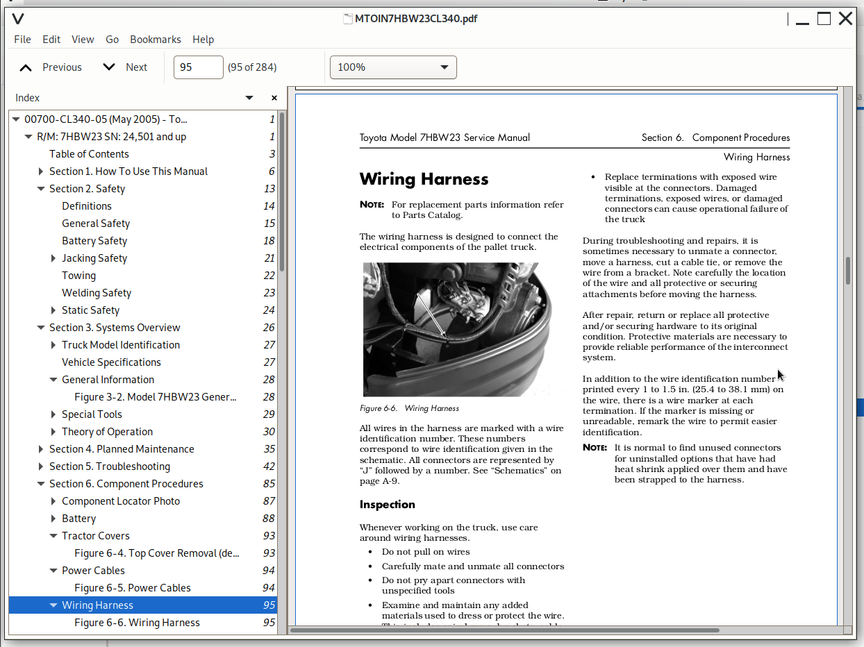
Figure 6-6. Wiring Harness.....95
Fuses.....96
Figure 6-7. Fuse/Circuit Breaker Location.....96
Circuit Breaker.....97
Test/Inspection.....97
Figure 6-8. Circuit Breaker Location.....97
Control Handle.....98
Control Handle Disassembly.....99
Figure 6-9. Horn Button Removal.....99
Figure 6-10. Lift/Lower Button Removal.....100
Figure 6-11. Push Button Removal.....100
Control Handle Stem.....100
Figure 6-12. Removing Cover.....100
Figure 6-13. Cover Removed.....100
Figure 6-14. Allen Head Cap Screws.....101
Horn (H1).....102
Figure 6-15. Horn Location.....102
Power Amplifier (A1).....103
Figure 6-16. Power Amplifier Location.....103
Contactors.....104
Main Contactor (K10).....104
Figure 6-17. Main Contactor K10.....104
Lift Motor Contactor (K30).....104
Figure 6-18. Lift Motor Contactor K30.....104
Master Control Relay (K4).....105
Inspection/Test.....105
Figure 6-19. Master Control Relay (K4).....105
Switches (General).....107
Test/Inspection.....107
Master Control ON/OFF Switch.....107
Figure 6-20. Master Control ON/OFF Switch Location.....107
Arm Angle Switches.....108
Figure 6-21. Arm Angle Switches.....108
Figure 6-22. Arm Angle Switch Screws.....108
Figure 6-23. Control Handle Cover Installed.....108
Lift-Limit Switch.....109
Figure 6-24. Lift-Limit Switch.....109
Key Switch (Optional).....110
Drive Unit.....111
Transmission Assembly.....111
Figure 6-25. Control Handle Assembly Removal.....111
Figure 6-26: Terminal Block.....111
Figure 6-27. Transmission Assembly, Exploded View.....113
Drive Housing Lubrication.....114
Figure 6-28. Transmission Assembly Fill/Drain Plugs.....114
Drive Wheel.....115
Figure 6-29. Drive Wheel Nuts.....115
Figure 6-30. Tire Replacement.....115
Electromagnetic Brake.....117
Brake Disc Location.....117
Figure 6-31. Brake Location.....117
Air Gap Adjustment.....117
Figure 6-32. Brake Gap Adjustment.....117
Friction Disc Replacement.....118
Figure 6-33: Friction Disc Replacement.....118
Mechanically Releasing the Brake.....118
Motors, General.....119
Drive Motor Brush Inspection.....119
Figure 6-34. Drive Motor Brush, Typical Location.....119
Drive Motor Brush Spring Tension.....120
Figure 6-35. Motor Brush Spring Tension Inspection.....120
Motor Commutator.....120
Figure 6-36. Mica Inspection.....120
Terminal Nuts.....123
Figure 6-37. Motor Terminal Nuts.....123
Electric Motor Tests.....123
Figure 6-38. Motor Circuits.....123
Drive Motor.....126
Figure 6-39: Drive Motor Brush Shield.....126
Pallet Forks and Load Wheels.....129
Load Wheels.....129
Figure 6-40. Removing Set Screw.....129
Load Wheel Pull Rod.....129
Figure 6-41. Wheel Fork Set Screw Location (top view).....129
Carrier Frame Linkage.....130
Figure 6-42: Lower Links.....130
Hydraulic Components.....131
General Guidelines.....131
Hydraulic Cylinder.....131
Figure 6-43. Remove Retaining Clip.....131
Figure 6-44. Hydraulic Cylinder (shown extended with retaining clip removed).....131
Figure 6-45. Hydraulic Cylinder Disassembly.....132
Hydraulic Solenoid.....133
Figure 6-46. Hydraulic Solenoid.....133
Hydraulic Unit.....133
Figure 6-47. Hydraulic Unit.....134
Hydraulic Reservoir.....134
Filter Screen and Inlet Tube.....134
Figure 6-48. Cleaning Filter Screen.....135
Hydraulic Pump.....135
Lift Motor.....135
Hydraulic Fluid.....136
Figure 6-49. Hydraulic Connections.....136
Adjusting Hydraulic Pump Pressure Relief Valve.....137
Figure 6-50. Checking Relief Valve Pressure.....137
Cold Storage Conditioning.....139
Lubrication Equivalency Chart.....143
Torque Chart - Standard.....144
Torque Chart - Metric.....145
Decimal Equivalent Chart.....146
Standard/Metric Conversions.....148
Figure A-1. Electrical Schematic - Sheet 1 of 2.....152
Figure A-2. Electrical Schematic - Sheet 2 of 2.....153
Figure A-3. Hydraulic Schematic.....154
Index.....156
00715-00120-05 - Toyota Electric Walkie Low-Lift Pallet Truck 7HBW23 Master Quality Parts Manual.....160
Front Cover.....160
Parts Ordering Instructions.....161
General Information.....162
Index.....165
0000 Chassis.....167
0340-000 Inspection covers (Shields & guards).....169
0342-000 Inspection covers (“EE” electrical box).....171
0380-002 Fork frame.....173
0850-000 Signs, warnings.....177
1000 Motors.....179
1750-100 Pump motor.....181
1760-000 Drive motor assembly.....183
2000 Transmission / Drive Gear.....185
2550-000 Transmission assembly.....187
3000 Brake / Wheel System.....189
3370-000 Electromagnetic parking brake.....191
3530-000 Drive wheel.....193
3540-000 Support (skid shoe).....195
3540-100 Support (caster wheel).....197
3550-000 Load wheel.....199
3560-100 Caster wheel.....201
4000 Steering System.....203
4110-001 Steering arm / wheel (Tiller arm).....205
4111-001 Steering control head.....207
4180-000 Steering bearing.....211
5000 Electrical System.....213
5110-001 Battery pack, swing out.....215
5110-101 Battery pack, swing out, power wires.....217
5113-001 Battery pack (GNB Pallet Pro™ Start / Stop charger).....219
5180-000 Current collector (Static strap “EE”).....221
5190-001 Battery contactor / plug (Battery connector).....223
5311-000 Start / stop switch.....225
5390-000 Control cables / harness Serial number 24501 - 25304.....227
5390-001 Control cables / harness Serial number 25305 - UP.....229
Serial Number 25305 - UP.....228
5433-000 Motor cables Serial number 24501 - 25304.....231
Serial Number 24501 - 25304.....230
5433-001 Motor cables Serial number 25305 - UP.....233
5436-001 Contactor panel.....235
5460-000 Drive controller.....237
6000 Hydraulic System.....239
6100-100 Hydraulic pump.....241
6125-100 Hoses, pipes, connections, mounting points.....243
6420-000 Lift cylinder.....245
7000 Operating Function - Lifting Device.....247
8000 Peripheral / Installation Equipment.....249
9000 Options / Attachments.....251
9720-100 Removable load backrest.....253
10000 Tools.....255
10020-001 Special tools and lubrications.....257
10020-002 Special tools (seal installing).....259
11000 Alphabetical / Numerical Index.....261
Alphabetical Index.....263
Numerical Index.....267
Toyota Electric Walkie Low-Lift Pallet Truck 7HBW23 Programming QuickGuide.....272
wiring_diagram.....280
1042401a_7hbw23_schematic.....280
7hbw23 sn 24501- repair manual cl340-05 wiring diagram.....282
Toyota Electric Powered Pallet Truck Model 7HBW23 Repair Service Manual
![]()