
Toyota Pallet Trucks 8HBW30, 8HBE30-40, 8HBC30-40, 8TB50 Repair Service Manual + Parts Manual
Complete service repair manual with Electrical Wiring Diagrams for Toyota Pallet Trucks Models 8HBW30, 8HBE30, 8HBE40, 8HBC30, 8HBC40, 8TB50, with all the technical information to maintain, diagnose, repair, and service like professional mechanics.
Toyota 8HBW30, 8HBE30, 8HBE40, 8HBC30, 8HBC40, 8TB50 series workshop service repair manual includes:
* Numbered table of contents easy to use so that you can find the information you need fast.
* Detailed sub-steps expand on repair procedure information
* Numbered instructions guide you through every repair procedure step by step.
* Troubleshooting and electrical service procedures are combined with detailed wiring diagrams for ease of use.
* Notes, cautions and warnings throughout each chapter pinpoint critical information.
* Bold figure number help you quickly match illustrations with instructions.
* Detailed illustrations, drawings and photos guide you through every procedure.
* Enlarged inset helps you identify and examine parts in detail.
PRODUCT DETAILS:
Total Pages: 613 pages
File Format: PDF (Internal Links, Bookmarked, Table of Contents, Searchable, Printable, high quality)
Language: English
00700-CL398-09 - Toyota Pallet Trucks 8HBW30, 8HBE30, 8HBE40, 8HBC30, 8HBC40, 8TB50 Repair Manual.pdf
00700-CL398-07 - Toyota Pallet Trucks 8HBW30, 8HBE30, 8HBE40, 8HBC30, 8HBC40, 8TB50 Repair Manual.pdf
00715-00130-08 - Toyota 8HBW30, 8HBE30-40, 8HBC30-40, 8TB50 Parts Manual (Serial Number 36,001 and Up).pdf
Operator Display And Programming AC Pallet Jacks - HBW30, 8HBE30.40, 8HBC30.40, 8TB50.pdf
Wiring Diagram 8HBC30-40, 8HBE30-40, 8HBW30, 8TB50.pdf
MAIN SECTIONS
00700-CL398-07 - Toyota Pallet Trucks 8HBW30, 8HBE30, 8HBE40, 8HBC30, 8HBC40, 8TB50 Repair Manual.......1
Front Cover.......1
Table of Contents.......4
Section 1. How To Use This Manual .......7
Map of the Manual .......8
Manual Design .......9
Abbreviations & Symbols .......10
START Page .......13
Section 2. Safety .......16
Definitions .......17
General Safety .......18
Battery Safety .......21
Jacking Safety .......24
Tie-Down for Transport .......25
Figure 2-1. Tie-Down for Transport .......25
Towing .......26
Welding Safety .......27
Static Safety .......28
Figure 2-2. Anti-Static Kit (P/N 00590-04849-71) With Wrist Strap and Mat .......28
Section 3. Systems Overview .......31
Truck Model Identification .......32
Vehicle Specifications .......33
Maximum Speeds .......34
Tractor First .......34
Forks First .......34
General System Data .......35
Figure 3-1. Model 8HBE30/40 (Long-John Forks Shown) .......35
Figure 3-2. Model 8HBE30/40 Control Handle .......36
Special Tools .......37
Service Key .......37
Figure 3-3. Service Key .......37
Theory of Operation .......38
Vehicle Manager (VM) .......38
Traction Power Amplifier (TPA) .......38
Traction System .......38
Emergency Reverse (Model 8HBW30 and 8HBE30/40) .......39
Strip Curtain Bypass (Model 8HBE30/40 only) .......39
Lift/Lower System .......40
Jog Pick Mode .......40
Model 8HBE30/40 only .......41
Manual Jog Pick .......41
Section 4. Planned Maintenance .......44
Maintenance Guidelines .......45
Initial 90 Day/250 Deadman Hours (HD) Maintenance .......46
Every 180 Days or 500 Deadman Hours .......47
Every 360 Days or 2000 Deadman Hours (HD) .......49
Grease Fittings .......50
Figure 4-1. Caster Grease Fittings .......50
Figure 4-2. Upper Bell Crank Grease Fittings (Between Tractor and Fork Section) .......50
Figure 4-3. Lower Bell Crank Grease Fittings-left side shown (Between Tractor and Fork Section) .......50
Figure 4-4. Load Wheel Grease Fittings and Fork Grease Fittings (Top View-8K trucks) .......51
Section 5. Troubleshooting .......53
How to Use This Section .......54
Electrical Troubleshooting Guidelines .......55
Troubleshooting the CAN Bus .......55
Checking for Shorts from Battery to Truck Frame .......57
Checking for Shorts from Components to Truck Frame .......58
DC Electric Motor Tests .......59
DC Motor Types .......59
Figure 5-1. Motor Circuits .......59
Open Circuit Motor Test .......59
Grounded Motor Test .......59
Short-Circuited Winding .......60
Short-Circuited Armature .......60
AC Electric Motor Tests .......61
Figure 5-2. AC Traction Motor circuits .......61
AC Motor Type .......61
Open Winding .......61
Shorted Winding .......61
Hydraulic Troubleshooting Guidelines .......62
Definitions .......63
Figure 5-3. Brake (Deadman) Switch and Brake Actuation .......63
List of Electrical Symbols .......67
Operator Display and Programming .......69
Figure 5-4. Operator Display .......69
Special Truck Mode .......69
Hour Meter (H) .......69
Error Codes (E) .......69
Changing Truck Parameters (P) .......70
Service Input/Output Displays .......75
Figure 5-5. Service Key Connection Point .......75
Figure 5-6. Operator Display .......75
Digital Inputs/Outputs from Traction Power Amplifier and VM .......76
Traction Power Amplifier LED Diagnostics .......78
Figure 5-7. Traction Power Amplifier Status Indicator LED .......78
Traction Power Amplifier Flash Codes .......79
Troubleshooting Flowcharts .......81
Caution and Error Codes .......85
Figure 5-8: Operator Display .......85
Caution Codes .......85
Error Codes .......97
Symptom Tables: Lift/Lower System .......107
Symptom Tables: Travel (Forward/Reverse) System .......111
Symptom Tables: Wiring System .......120
Pinout Matrix .......121
Section 6. Component Procedures .......136
List of Component Procedures .......137
Component Locator Photos .......140
Figure 6-1. Inside Tractor, Rear View .......140
Figure 6-2. Inside Tractor, Right Side .......141
Tractor Cover .......142
Figure 6-3. Cover Handle Hold Locations .......142
Battery .......143
With Battery Gates and Rollers (Optional) .......143
Battery Gates (Optional) .......143
Battery Rollers (Optional) .......143
Without Battery Gates and Rollers .......143
Battery Exterior Cleaning .......144
Figure 6-4. Battery Filler Plugs and Vent Holes .......144
Testing, Charging, and Maintenance .......145
Maintenance-Free Batteries .......145
Storage .......145
Power Cables .......146
Wiring Harness .......147
Fuses .......149
Figure 6-5. Fuse Location .......149
Switches (General) .......150
Key Switch (SW1) .......151
Figure 6-6. Key Switch Location .......151
Brake (Deadman) Switch (SW2) .......152
Figure 6-7. Brake (Deadman) Switch, 8HBW30 and 8HBE30 or 8HBE40 .......152
Figure 6-8. Brake (Deadman) Switch Active, 8HBW30 and 8HBE30 or 8HBE40 .......152
Lift-Limit Switch (SW8) .......154
Figure 6-9. Lift-Limit Switch .......154
Grab Rail Switches .......155
Model 8HBE30/40 Only .......155
Figure 6-10. Grab Rail Switch Removal, Left Side .......155
Figure 6-11: Grab Rail Switch Removal, Right Side .......155
Hydraulic Solenoids .......156
Figure 6-12. Hydraulic Solenoids (typical unit) .......156
Jog Pick Solenoid .......157
Model 8HBE30/40 (Optional) .......157
Figure 6-13. Socket Head Cap Screws .......157
Figure 6-14. Removed Solenoid Mechanism .......157
Jog Pick Solenoid Switch .......157
Canister .......158
Figure 6-15. Canister Spacing .......158
Horn .......159
Figure 6-16. Horn Location .......159
Traction Power Amplifier .......160
Figure 6-17. Traction Power Amplifier Location .......160
Figure 6-18. Removing the Traction Power Amplifier .......160
AMP Harness/Traction Power Amplifier Connector .......162
Connector Components .......162
Figure 6-19. JP1 Connector Components .......162
Figure 6-20. AMP JP1 Connector .......162
Figure 6-21. Contact Insertion .......163
Figure 6-22. Wedge Lock Latches .......163
Figure 6-23. Wedge Lock Flush With Housing .......164
Contactors .......165
Figure 6-24. Disconnecting Main Contactor .......165
Main Contactor .......165
Figure 6-25. Removing Top Cover .......165
Figure 6-26. Removing Brass Lock Nuts .......166
Figure 6-27. Removing the Fixed Contacts .......166
Figure 6-28. Installing Fixed Contacts .......166
Figure 6-29. Main Contactor Components .......166
Figure 6-30. Installing the Main Contactor .......167
Control Handle Assembly .......168
Spring-Loaded Handle Design - Models 8HBW30 and 8HBE30 or 8HBE40 .......168
Figure 6-31. Control Handle Base Cover Removal .......168
Figure 6-32. Control Handle Wire Harness .......168
Figure 6-33. Remove Jam Nut at Coast Link .......168
Figure 6-34: Return Spring Rod Removal .......169
Return Spring Adjustment .......169
Figure 6-35. Return Spring Adjustment .......169
Fixed-Position Handle Design - Models 8HBC30/40 and 8TB50 .......170
Control Handle .......171
Figure 6-36. Handle and Control Head Assembly .......171
Figure 6-37. Control Head Assembly -Exploded View .......172
Control Head Removal .......173
Figure 6-38. Horn Button Removal .......174
Figure 6-39. Lift/Lower Button Removal .......174
Figure 6-40. Push Button Removal .......174
Figure 6-41. Handle with Jog Pick Option .......175
Brake .......176
Spring-Loaded Handle - Models 8HBW30 and 8HBE30 or 8HBE40 .......176
Figure 6-42. Brake Adjustment, location .......176
Figure 6-43: Brake Adjusting Screw .......176
Figure 6-44. Brake Drum With Control Handle and Brake Shield Removed .......177
Figure 6-45. Brake Adjusting Screw .......177
Figure 6-46. Brake Adjusting Rod (Installed) .......177
Fixed-Position Handle - Models 8HBC30/40 and 8TB50 .......178
Motors, General .......180
Terminal Nuts .......180
Figure 6-47. Traction Motor Terminal Connections .......180
Figure 6-48. Lift and Aux Motor Terminal Nuts .......180
Traction Motor .......181
Figure 6-49. Control Handle Base Cover Removal .......181
Figure 6-50. Control Handle Mounting Frame Removal .......181
Figure 6-51. Traction Motor Power Cables .......181
Figure 6-52. Traction Motor Removal .......182
Figure 6-53. Drive Unit Pinion Gear .......182
Figure 6-54. Main Case Location .......182
Figure 6-55. Traction Motor Installation .......183
AC Motor Service .......184
AC Motor Temperature Sensor .......184
Drive Unit .......186
Figure 6-56. Drive Unit Fill Plug .......186
Figure 6-57. Drive Unit Drain Plug .......186
Figure 6-58. Drive Unit Mounting (Traction Motor Removed) .......186
Steering Bearing .......187
Figure 6-59. Drive Unit (Shown installed in Tractor Frame) .......187
Figure 6-60. Drive Unit Bottom View .......187
Figure 6-61. Drive Unit, Steering Bearing Removed .......187
Figure 6-62. Steering Bearing Locating Groove .......187
Figure 6-63. Main Case Cover, Six Hole-Type, Installed .......188
Figure 6-64. Gear Housing and Cover .......188
Figure 6-65. Lower Drive Unit, Cross-Sectional View, Model 8HBW30 and 8HBE30 or 8HBE40 .......189
Gear Assembly .......190
Checking the Gears .......191
Figure 6-66. Drive Unit Gear Tooth Pattern .......191
Figure 6-67. Drive Unit Mounting Location in Frame .......192
Figure 6-68. Drive Unit Installed In Frame .......192
Figure 6-69. Drive Unit Shimming Locations .......192
Figure 6-70. Drive Unit Drain Plug .......193
Drive Housing Lubrication .......193
Figure 6-71. Drive Unit Fill Level Dipstick .......193
Figure 6-72. Drive Unit Drain Plug .......193
Drive Wheel .......195
Figure 6-73. Drive Wheel and Tire .......195
Figure 6-74. Cushion Tire Replacement .......195
Casters (Torsion) .......198
Figure 6-75. Removing Caster Wheel Assembly .......198
Caster Removal .......198
Figure 6-76. Caster Assembly, Disassembled .......198
Wheel Replacement .......198
Figure 6-77. Caster Assembly, Assembled .......199
Caster Assembly .......199
Caster Installation .......199
Figure 6-78. Securing Caster To Tractor .......199
Casters (Spring-Loaded) .......200
Figure 6-79. Removing Spring-Loaded Caster .......200
Removal .......200
Wheel Replacement .......200
Figure 6-80. Removing Axle Shaft .......200
Figure 6-81. Removing Tension Pin .......200
Figure 6-82. Removed Wheel and Shims .......201
Figure 6-83. Compressing Caster Springs .......201
Caster Disassembly .......201
Figure 6-84. Relieving Pivot Tension .......201
Figure 6-85. Removing Pivot Pin Retainer Screw .......201
Figure 6-86. Removing Pivot Pin .......202
Figure 6-87. Separated Caster .......202
Caster Assembly .......202
Figure 6-88. Removing Bolts from Springs .......202
Figure 6-89. Installing New Wheel .......202
Wheel Installation .......203
Figure 6-90. Installing Axle Shaft .......203
Figure 6-91. Installing Tension Pin .......203
Figure 6-92. Caster, Shims and Mounting Bolts .......203
Caster Installation .......203
Figure 6-93. Securing Caster To Tractor .......203
Load Wheels .......204
Figure 6-94. Removing Tension Pin .......204
Models 8HBW30, 8HBE30/40 and 8HBC30/40 .......204
Figure 6-95. Removing Axle From Load Arm Casting .......204
Figure 6-96. Removed Load Wheel and Components .......204
Model 8TB50 .......205
Figure 6-97. Model 8TB50 Load Wheel Suspension-Exploded View .......205
Load Wheel Suspension (Optional) .......206
Figure 6-98. Model 8TB50 Optional Load Wheel Suspension-Exploded View .......206
Pallet Entry Sliders .......207
Figure 6-99. Replacing Pallet Entry Slider (6000 lb. Standard Model Shown) .......207
Fork Height Adjustment .......208
Figure 6-100. Fork Height Adjustment at Lower Bell Crank .......208
Measurement .......208
Adjustment .......208
Hydraulic Components .......210
General Guidelines .......210
Figure 6-101. Hydraulic Unit (typical shown) .......210
Hydraulic Fluid .......211
Figure 6-102. Hydraulic Connections .......211
Adjusting Hydraulic Pump Relief Valve Pressure .......212
Figure 6-103. Checking Relief Valve Pressure .......212
Relief Valve Settings .......212
Check Valve .......213
Hydraulic Ram .......214
Figure 6-104. Blocking Fork Section For Ram Removal .......214
Figure 6-105. Removing Lower Bell Crank Pins .......214
Figure 6-106. Disconnecting Upper Clevis Brackets .......215
Figure 6-107. Hydraulic Ram Area, Forks Removed .......215
Figure 6-108. Hydraulic Line Connection .......215
Figure 6-109. Vent Hose Connections .......215
Figure 6-110. Hydraulic Ram Removal/Installation .......216
Figure 6-111. Hydraulic Line Connection (installed) .......216
Hydraulic Cylinder Seals .......217
Figure 6-112. Remove Outer Spiral Lock Ring .......217
Figure 6-113. Remove the Spacer .......217
Figure 6-114. Remove Head Lock Ring From Cylinder .......217
Figure 6-115. Rod and Head Assembly Out of Cylinder .......218
Figure 6-116. Remove the Piston Jam Nut .......218
Figure 6-117. Piston Rod Components .......218
Figure 6-118. Securing Piston Jam Nut .......218
Figure 6-119. Installing the Head Lock Ring .......219
Figure 6-120. Installing the Outer Lock Ring .......219
Hydraulic Unit .......220
Figure 6-121. Hydraulic Unit (typical shown) .......220
Hydraulic Reservoir .......221
Figure 6-122. Adapter Cap Screws .......221
Figure 6-123. Removed Reservoir .......221
Figure 6-124. Pump Housing Components .......221
Filter Screen and Suction Tube .......222
Figure 6-125. Cleaning Filter Screen .......222
Figure 6-126. Pump and Adapter Body .......222
Hydraulic Pump .......222
Figure 6-127. Pump Drive Coupling .......222
Figure 6-128. Installing Pump In Adapter .......223
Lift Motor .......224
General Data .......224
Figure 6-129. Bolts Securing Motor To Adapter .......224
Figure 6-130. Separated Reservoir and Motor (typical) .......224
Figure 6-131. Coupling Cavity .......225
Figure 6-132. Indexing Pin .......225
Cold Storage Conditioning .......226
Section A. Appendix .......229
Lubrication Equivalency Chart .......230
Torque Chart - Standard (Ferrous) .......231
Torque Chart - Standard (Brass) .......232
Torque Chart - Metric .......233
Torque Chart - Thread-Forming Screws .......234
Decimal Equivalent Chart .......235
Standard/Metric Conversions .......237
Electrical Schematics .......240
Figure B-1. Model 8HBW30 Electrical Schematic (Sheet 1 of 2) .......241
Figure B-2. Model 8HBE30/40 End Rider Electrical Schematic (Sheet 1 of 2) .......243
Figure B-3. Model 8HBC30/40 Center Rider Electrical Schematic (Sheet 1 of 2) .......245
Figure B-4. Model 8TB50 Electrical Schematic (Sheet 1 of 2) .......247
Figure B-5. Electrical Schematic - Legend (Sheet 1 of 2) .......249
Figure B-6. Hydraulic Schematic .......251
Section I. Index .......253
00700-CL398-09 - Toyota Pallet Trucks 8HBW30, 8HBE30, 8HBE40, 8HBC30, 8HBC40, 8TB50 Repair Manual.......259
Table of Contents.......260
Page Revision Record.......266
Document Revision History.......266
Service Bulletins List.......268
Product Improvement Notices List.......269
Section 1. How To Use This Manual.......270
Map of the Manual.......271
Manual Design.......272
Abbreviations & Symbols.......273
START Page.......275
Section 2. Safety.......278
Definitions.......279
General Safety.......280
Battery Safety.......283
Jacking Safety.......285
Tractor Section.......285
Fork Section.......285
Tie-Down for Transport.......286
Figure 2-1. Tie-Down for Transport.......286
Towing.......287
Static Safety.......288
Figure 2-2. Anti-Static Kit (P/N 1-187-059) With Wrist Strap and Mat.......288
Welding Safety.......289
Section 3. Systems Overview.......290
Introduction.......291
Truck Model Identification.......292
Figure 3-1. Model 8HBW30 Low Lift Walk-Behind.......292
Figure 3-2. Model 8HBE30/40 End Rider.......292
Figure 3-3. Model 8HBC30/40 Center Rider.......292
Figure 3-4. Model 8TB50 Tow Tractor.......292
Lift Truck Specifications.......293
Figure 3-5. Lift Truck Specification Plate - Models 8HBW, 8HBE, and 8HBC Pallet Trucks.......293
Figure 3-6. Lift Truck Specification Plate - Model 8TB50 Tow Tractor.......293
General System Data.......294
Figure 3-7. Model 8HBE30/40 (Long-John Forks Shown).......294
Figure 3-8. Model 8HBE30/40 Control Handle.......295
Special Tools.......296
Service Key.......296
Figure 3-9. Service Key.......296
Operator Display and Programming.......297
Figure 3-10. Operator Display.......297
Special Truck Mode.......297
Hour Meter (H).......297
Error Codes (E).......297
Error Code History.......297
Changing Truck Parameters (P).......298
Programming Operator Parameters.......298
Programming Service Parameters.......299
Service Parameter Display (Keypad Only).......299
Setting Individual PIN-Key Codes (Keypad Only).......300
Display Part Numbers (Pn).......303
Diagnostic Test Display (D).......303
Service Input/Output Displays.......304
Figure 3-11. Service Key Connection Point.......304
Figure 3-12. Operator Display.......304
Digital Inputs/Outputs from Traction Amplifier and VM.......305
Traction Amplifier Inputs.......305
Traction Amplifier Outputs.......305
Digital Input From VM Control Sensors.......306
Digital Input From VM Control Sensors.......306
Toyota FlashWare.......307
Overview.......307
Requirements.......307
Installing FlashWare on PC.......307
Connecting PC to Truck.......307
Starting FlashWare.......307
Figure 3-13. Truck Opening Screen with Menu.......308
Configuration and Truck Setup Options.......309
Figure 3-14. Typical Truck Setup Screen.......309
Changing Truck Parameters:.......309
Figure 3-15. Change Parameter.......309
Figure 3-16. Send Changes Button.......310
Software Management.......311
Figure 3-17. Truck Setup Screen Software Button.......311
Figure 3-18. Truck Software Window.......312
Erase Vehicle Manager.......312
Figure 3-19. Erase Vehicle Manager Software Screen.......312
Reset Defaults.......312
Diagnostics.......312
Error Log.......313
RE_Read Truck Settings.......313
SAVE Settings to File.......313
SEND Changes to Truck.......313
Section 4. Planned Maintenance.......314
Maintenance Guidelines.......315
Initial 90 Day/250 Deadman Hours (HD) Maintenance.......316
Every 180 Days or 500 Deadman Hours.......317
Every 360 Days or 2000 Deadman Hours (HD).......319
Contactor Tip Inspection.......320
Grease Fittings (All Models).......321
Figure 4-1. Caster Grease Fittings.......321
Figure 4-2. Load Wheel Grease Fittings.......321
Grease Fittings (Trucks without Composite Bushings Only).......322
Figure 4-3. Upper Bell Crank Grease Fittings (Between Tractor and Fork Section).......322
Figure 4-4. Lower Bell Crank Grease Fittings-left side shown (Between Tractor and Fork Section).......322
Figure 4-5. Lower Bell Crank Grease Fittings-left side shown (Between Tractor and Fork Section).......322
Figure 4-6. Fork Grease Fittings (Top View).......322
Section 5. Troubleshooting.......324
How to Use This Section.......325
Troubleshooting Flowcharts.......326
TS1: START TROUBLESHOOTING.......326
Figure 5-1. TS1: START TROUBLESHOOTING.......326
GEN1: General Troubleshooting.......327
Figure 5-2. GEN1: General Troubleshooting.......327
END1: End of Troubleshooting Procedure.......328
Figure 5-3. END1: End of Troubleshooting Procedure.......328
Electrical Troubleshooting Guidelines.......329
Troubleshooting the CAN Bus.......329
Test the Main Wire Harness.......330
Test the Stem Harness.......330
Test the Grab Rail.......330
Test the Traction Amplifier and Vehicle Manager.......330
Shorts to Frame Test.......331
Fuses.......334
Figure 5-4. Fuse Location.......334
Test/Inspection.......334
DC Electric Motors.......335
DC Motor Types.......335
Figure 5-5. Motor Circuits.......335
Inspection.......335
Service.......335
Open Circuit Motor Test.......337
Grounded Motor Test.......338
Short-Circuited Armature.......338
Short-Circuited Winding.......338
AC Electric Motors.......339
AC Motor Type.......339
Figure 5-6. AC Traction Motor circuit - Phase A.......339
Figure 5-7. AC Traction Motor circuit - Phase B.......339
Open Winding.......339
Shorted Winding.......339
Hydraulic Troubleshooting Guidelines.......340
Symptom Tables: Lift/Lower System.......341
Symptom Tables: Travel (Forward/Reverse) System.......344
Symptom Tables: Wiring System.......349
Section 6. Messages and Codes.......350
List of Messages and Codes.......351
Traction Amplifier LED Diagnostics.......352
Figure 6-1. Traction Amplifier Status Indicator LED.......352
Traction Amplifier Flash Codes.......353
Caution and Error Codes.......355
Figure 6-2. Operator Display.......355
Caution Codes.......356
Error Codes.......370
Section 7. Component Procedures.......380
List of Component Procedures by Truck System.......381
Component Locator Photos.......384
Figure 7-1. Inside Tractor, Rear View.......384
Figure 7-2. Inside Tractor, Right Side.......385
Figure 7-3. Inside Tractor, Left Side.......386
Control Handle - Model 8HBW30.......389
Figure 7-4. Model 8HBW30 Control Head Assembly - Exploded View.......389
Control Handle Disassembly.......390
Changing Horn Button/Switch [26, 27].......390
Figure 7-5. Horn Button Removal.......390
Changing Lift/Lower Button [22].......391
Figure 7-6. Lift/Lower Button Removal.......391
Changing Push Button [19].......391
Figure 7-7. Push Button Removal.......391
Spring-Loaded Handle Design.......392
Removal.......392
Figure 7-8. Control Handle Base Cover Removal.......392
Figure 7-9. Control Handle Wire Harness.......392
Figure 7-10. Remove Jam Nut at Coast Link.......392
Figure 7-11. Return Spring Rod Removal.......393
Installation.......393
Return Spring Adjustment.......393
Figure 7-12. Return Spring Adjustment.......393
Fixed-Position Handle Design - Models 8HBC30/40 and 8TB50.......395
Removal.......395
Installation.......395
Control Handle Assemblies - Models 8HBE, 8HBC and 8TB50.......396
Figure 7-13. Control Handle and Head Assembly - Model 8HBE30/40.......396
Figure 7-14. Control Handle with Hand Brake - Model 8HBC30/40 and 8TB50 (Fixed Handle).......397
Figure 7-15. Control Handle with Deadman Brake - Model 8HBC30/40 and 8TB50 (Spring-Loaded Handle).......398
Figure 7-16. Control Head Assembly (Models 8HBE30/40, 8HBC30/40, and 8TB50) - Exploded View.......399
Control Head Removal.......400
Changing Horn Button/Switch [24].......400
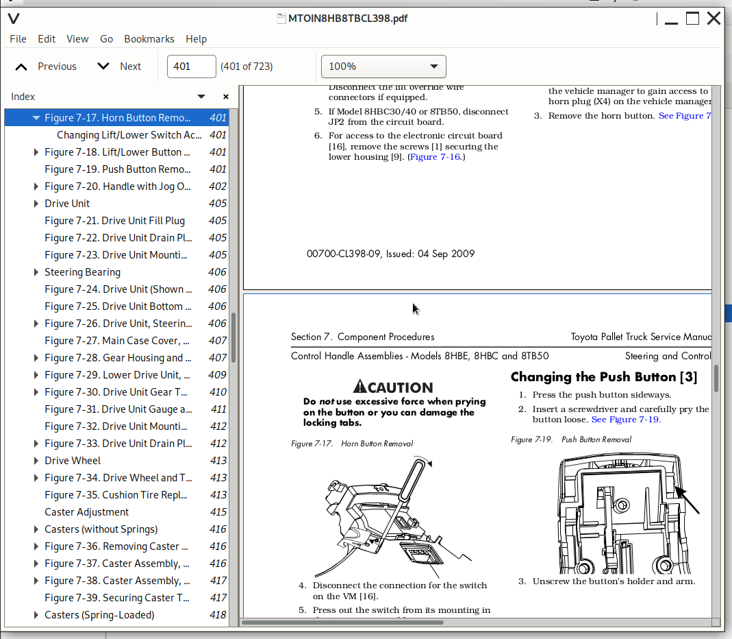
Figure 7-17. Horn Button Removal.......401
Changing Lift/Lower Switch Activator [14].......401
Figure 7-18. Lift/Lower Button Removal.......401
Changing the Push Button [3].......401
Figure 7-19. Push Button Removal.......401
Figure 7-20. Handle with Jog Option.......402
Changing the Jog Trigger Switch [44].......402
Changing the Jog Trigger and Spring.......402
Drive Unit.......405
Removal.......405
Figure 7-21. Drive Unit Fill Plug.......405
Figure 7-22. Drive Unit Drain Plug.......405
Figure 7-23. Drive Unit Mounting (Traction Motor Removed).......405
Steering Bearing.......406
Removal.......406
Figure 7-24. Drive Unit (Shown installed in Tractor Frame).......406
Figure 7-25. Drive Unit Bottom View.......406
Figure 7-26. Drive Unit, Steering Bearing Removed.......406
Installation.......406
Figure 7-27. Main Case Cover, Six Hole-Type, Installed.......407
Figure 7-28. Gear Housing and Cover.......407
Gear Assembly.......407
Figure 7-29. Lower Drive Unit, Cross-Sectional View.......409
Checking the Gears.......410
Adjusting Tooth Pattern of Drive Unit.......410
Figure 7-30. Drive Unit Gear Tooth Pattern.......410
Installation.......411
Figure 7-31. Drive Unit Gauge and Shimming Locations.......411
Figure 7-32. Drive Unit Mounting Screw Torque Sequence.......412
Figure 7-33. Drive Unit Drain Plug.......412
Drive Housing Lubrication.......412
Drive Wheel.......413
Removal.......413
Figure 7-34. Drive Wheel and Tire.......413
Cushion Tire Replacement.......413
Figure 7-35. Cushion Tire Replacement.......413
Caster Adjustment.......415
Casters (without Springs).......416
Caster Removal.......416
Figure 7-36. Removing Caster Wheel Assembly.......416
Wheel Replacement.......416
Figure 7-37. Caster Assembly, Disassembled.......416
Caster Assembly.......416
Figure 7-38. Caster Assembly, Assembled.......417
Caster Installation.......417
Figure 7-39. Securing Caster To Tractor.......417
Casters (Spring-Loaded).......418
Removal.......418
Figure 7-40. Removing Spring-Loaded Caster.......418
Wheel Replacement.......418
Figure 7-41. Removing Tension Pin.......418
Figure 7-42. Removing Axle Shaft.......418
Figure 7-43. Removed Wheel and Shims.......418
Caster Disassembly.......419
Figure 7-44. Compressing Caster Springs.......419
Figure 7-45. Relieving Pivot Tension.......419
Figure 7-46. Removing Pivot Pin Retainer Screw.......419
Figure 7-47. Removing Pivot Pin.......419
Figure 7-48. Separated Caster.......419
Caster Assembly.......420
Figure 7-49. Removing Bolts from Springs.......420
Wheel Installation.......420
Figure 7-50. Installing New Wheel.......420
Figure 7-51. Installing Axle Shaft.......420
Figure 7-52. Installing Tension Pin.......420
Caster Installation.......420
Figure 7-53. Caster, Shims and Mounting Bolts.......421
Figure 7-54. Securing Caster To Tractor.......421
Brake.......422
Spring-Loaded Handle.......422
Figure 7-55. Brake Release Bolt Storage Location.......422
Removal.......422
Figure 7-56. Brake Release Bolts, Installed.......422
Figure 7-57. Brake Release Bolts, Installed.......422
Installation.......422
Checking the Gap.......423
Figure 7-58. Measuring Brake Gap.......423
Replacing the Rotor.......423
Battery.......425
With Battery Gates and Rollers (Optional).......425
Battery Removal.......425
Battery Installation.......425
Battery Gates (Optional).......425
Inspection.......425
Battery Rollers (Optional).......425
Inspection.......425
Replacement.......425
Without Battery Gates and Rollers.......425
Battery Removal.......425
Battery Installation.......425
Battery Exterior Cleaning.......426
Figure 7-59. Battery Filler Plugs and Vent Holes.......426
Testing, Charging, and Maintenance.......426
Maintenance-Free Batteries.......427
Storage.......427
Power Cables.......428
Power Cable Repair.......428
Figure 7-60. Short Barrel Terminal.......428
Figure 7-61. Long Barrel Terminals.......429
Wiring Harness.......430
Terminology.......430
Inspection.......430
Repair.......430
Soldering Procedures.......431
AMP Water-Resistant Connectors.......432
Figure 7-62. AMP Water-Resistant Connector.......432
Pin Extraction.......432
Figure 7-63. AMP Pin Extraction.......432
Figure 7-64. Removing Wire.......433
Pin Insertion.......433
Figure 7-65. Wire Seal.......433
Figure 7-66. Wire Insertion.......433
Seals.......433
Figure 7-67. Sealing Plug.......433
Figure 7-68. Interface Seal.......434
Figure 7-69. Latching AMP Connector.......434
AMP Harness/Traction Amplifier Connector.......435
Connector Components.......435
Figure 7-70. JPT1 Connector Components.......435
Disassembly (Contact Removal).......435
Figure 7-71. AMP Connector (JT1 or JL1).......435
Contact Insertion.......435
Assembly.......435
Figure 7-72. Contact Insertion.......436
Figure 7-73. Wedge Lock Latches.......436
Figure 7-74. Wedge Lock Flush With Housing.......437
Testing.......437
Brake Potentiometer (VR1).......438
Removal.......438
Figure 7-75. Pot Cover Screw Locations.......438
Figure 7-76. Brake Control Assembly - Exploded View.......438
Installation.......438
Lift-Limit Switch (SW8).......439
Figure 7-77. Lift-Limit Switch.......439
Adjustment.......439
Grab Rail Switches - Model 8HBE30/40.......440
Removal.......440
Figure 7-78. Grab Rail Switch Removal, Left Side.......440
Figure 7-79. Grab Rail Switch Removal, Right Side.......440
Installation.......440
Hydraulic Solenoids.......441
Figure 7-80. Hydraulic Solenoids (typical unit).......441
Jog Pick Solenoid - Model 8HBE30/40 Option.......442
Removal.......442
Figure 7-81. Jog Pick Solenoid Location.......442
Figure 7-82. Socket Head Cap Screws.......442
Figure 7-83. Removed Solenoid Mechanism.......442
Installation.......443
Figure 7-84. Install Ball Bearings.......443
Jog Pick Solenoid Switch/Spring.......443
Removal.......443
Installation.......443
Jog Pick Canister.......443
Removal.......443
Installation.......443
Figure 7-85. Canister Spacing.......443
Repair.......444
Figure 7-86. Special Compression Tool.......444
Figure 7-87. Cylinder Secured In Hydraulic Press.......444
Figure 7-88. Removing Snap Ring.......444
Figure 7-89. Jog Pick Canister Components.......444
Figure 7-90. Assembling Coast PRO Canister.......445
Traction Amplifier.......446
Figure 7-91. Traction Amplifier Location.......446
Removal.......446
Figure 7-92. Removing the Traction Amplifier.......446
Installation.......446
Programming.......447
Motors, General.......448
Terminal Nuts.......448
Figure 7-93. Traction Motor Terminal Connections.......448
Figure 7-94. Lift and Auxiliary Motor Terminal Nuts.......448
Traction Motor.......449
Removal.......449
Figure 7-95. Control Handle Base Cover Removal.......449
Figure 7-96. Control Handle Base Cover Removal.......450
Figure 7-97. Traction Motor Power Cables.......450
Figure 7-98. Traction Motor Removal.......451
Figure 7-99. Drive Unit Pinion Gear.......451
Installation.......451
Figure 7-100. Main Case Location.......451
Lift Motor.......453
General Data.......453
Removal.......453
Figure 7-101. Bolts Securing Motor To Adapter.......453
Figure 7-102. Separated Reservoir and Motor (typical).......453
Installation.......453
Figure 7-103. Coupling Cavity.......453
Figure 7-104. Indexing Pin.......454
Hydraulic Components.......457
General Guidelines.......457
Figure 7-105. Hydraulic Unit (typical shown).......457
Hydraulic Fluid.......458
Checking Hydraulic Fluid Level.......458
Hydraulic Unit.......459
Removal.......459
Figure 7-106. Hydraulic Unit (typical shown).......459
Installation.......459
Hydraulic Reservoir.......460
Removal.......460
Figure 7-107. Adapter Cap Screws.......460
Figure 7-108. Removed Reservoir.......460
Installation.......460
Filter Screen and Suction Tube.......461
Removal.......461
Figure 7-109. Pump Housing Components.......461
Figure 7-110. Cleaning Filter Screen.......461
Installation.......461
Hydraulic Pump.......462
Removal.......462
Figure 7-111. Pump and Adapter Body.......462
Installation.......462
Figure 7-112. Pump Drive Coupling.......462
Figure 7-113. Installing Pump In Adapter.......462
Adjusting Hydraulic Pump Relief Valve Pressure.......463
Figure 7-114. Checking Relief Valve Pressure.......463
Checking Relief Valve Setting.......463
Alternate Method Using Rated Load on Pallets.......463
Hydraulic Ram.......465
Inspection.......465
Removal.......465
Figure 7-115. Removing Lower Bell Crank Pins.......465
Figure 7-116. Disconnecting Upper Clevis Brackets.......466
Figure 7-117. Hydraulic Ram Area, Forks Removed.......466
Figure 7-118. Hydraulic Line Connection.......466
Figure 7-119. Vent Hose Connections.......466
Installation.......467
Figure 7-120. Hydraulic Ram Removal/Installation.......467
Figure 7-121. Hydraulic Line Connection (installed).......467
Hydraulic Cylinder Seals.......469
Disassembly.......469
Figure 7-122. Remove Outer Spiral Lock Ring.......469
Figure 7-123. Remove the Spacer.......469
Figure 7-124. Remove Head Lock Ring From Cylinder.......469
Figure 7-125. Rod and Head Assembly Out of Cylinder.......469
Figure 7-126. Remove the Piston Jam Nut.......470
Figure 7-127. Piston Rod Components.......470
Assembly.......470
Figure 7-128. Correct Piston Seal Orientation.......470
Figure 7-129. Securing Piston Jam Nut.......470
Figure 7-130. Installing the Head Lock Ring.......471
Figure 7-131. Installing the Outer Lock Ring.......471
Top Linkage Subassembly.......473
Removal.......473
Figure 7-132. Blocking Fork Section.......473
Figure 7-133. Removing Lower Bell Crank Pins.......473
Figure 7-134. Disconnecting Upper Clevis Brackets.......474
Figure 7-135. Hydraulic Ram Area, Forks Removed.......474
Installation.......474
Figure 7-136. Hydraulic Ram Area, Installation.......474
Pull Rod Subassembly.......476
Removal.......476
Figure 7-137. Blocking Fork Section.......476
Figure 7-138. Removing Lower Bell Crank Pins.......476
Figure 7-139. Eccentric Pin and Retaining Screw.......476
Figure 7-140. Machined Fork Trail Assembly.......477
Figure 7-141. Machined Fork Trail Assembly.......477
Installation.......477
Figure 7-142. Hydraulic Ram Removal/Installation.......477
Load Wheel Suspension - Model 8TB50.......479
Removal.......479
Figure 7-143. Model 8TB50 Load Wheel Suspension - Exploded View.......479
Installation.......480
Fork Height Adjustment.......481
Figure 7-144. Fork Height Adjustment at Lower Bell Crank.......481
Measurement.......481
Figure 7-145. Measure Fork Height at Load Wheel.......481
Figure 7-146. Measure Fork Height at Battery Compartment.......481
Adjustment.......481
Figure 7-147. Eccentric Pin Adjustment.......482
Figure 7-148. Eccentric Pin Height Reference.......482
Figure 7-149. Downstop adjustment.......482
Cold Storage Conditioning.......485
Section 8. Theory of Operation.......486
Definitions.......487
Acceleration Rate.......487
Brake Lever Potentiometer (VR1) (Models with Fixed Position Handles).......487
Brake (Deadman) Switch (Models with Spring-Loaded Handle).......487
Figure 8-1. Brake (Deadman) Switch and Brake Actuation.......487
Continuity.......487
Controller Area Network (CAN).......487
Current Limiting.......487
Deceleration (Neutral Braking).......487
Emergency Reverse (Models 8HBW30 and 8HBE30 or 8HBE40).......488
Fault Codes.......488
High Pedal Disable (HPD).......488
Jog Speed.......488
Open Circuit.......488
Overvoltage Cutoff.......488
PIN-Key Code.......488
Pulse Width Modulation.......488
Ramp Shape.......488
Regenerative Braking.......488
Sequencing Delay.......489
Short Circuit or “Short”.......489
Speed Limiting.......489
Static Return to Off (SRO).......489
Thermal Cutback (Traction Amplifier).......489
Throttle Map.......490
Truck Off Delay (Keypad only).......490
Undervoltage Cutoff.......490
VM (Vehicle Manager).......490
Traction System.......491
Vehicle Manager (VM).......491
Traction Amplifier (TA).......491
Battery Plugged In.......491
Key Switch ON and M1 Energized.......491
Travel Request, Tractor-First.......492
Travel Request, Forks-First.......492
Strip Curtain Bypass (Model 8HBE30/40 only).......492
Emergency Reverse (Model 8HBW30 and 8HBE30/40).......493
Jog Mode.......493
Jog Pick Mode.......494
Model 8HBE30/40 only.......494
Lift/Lower System.......495
Lift.......495
Lower.......495
Pinout Matrix.......496
Section A. Appendix.......502
Lubrication Equivalency Chart.......503
Thread Adhesives, Sealants, and Lubricants.......504
Component Specific Service/Torque Chart.......505
Torque Chart - Standard (Ferrous).......507
Torque Chart - Standard (Brass).......508
Torque Chart - Metric.......509
Torque Chart - Thread-Forming Screws.......510
Decimal Equivalent Chart.......511
Standard/Metric Conversions.......513
List of Electrical Symbols.......515
Electrical Schematics.......520
Figure A-1. Model 8HBW30 Standard.......520
Figure A-2. Model 8HBE30/40 Standard.......521
Figure A-3. Model 8HBC30/40 Standard.......522
Figure A-4. Model 8TB50 Standard.......523
Figure A-5. Options.......524
Figure A-6. Component Legend.......525
Power Distribution Diagram.......526
Figure A-7. Power Distribution Diagram.......526
Hydraulic Schematic.......527
Figure A-8. Hydraulic Schematic.......527
Section I. Index.......528
00715-00130-08 - Toyota 8HBW30, 8HBE30-40, 8HBC30-40, 8TB50 Parts Manual (Serial Number 36,001 and Up).......534
Table of Contents .......535
SECTION 1 General Information .......537
To Our Customer .......538
How To Use Catalog If Part Number Is Not Known .......539
How To Use Catalog If Part Number Is Known .......540
Major Sections .......541
Recommended Spare Parts List .......542
Hardware Parts List .......543
SECTION 2 Finish and Accessories .......545
Major Assemblies .......546
Suspension Assembly, Model 8TB50 .......548
Suspension Assembly, Model 8TB50, Optional .......550
Caster Installation .......552
Caster Assembly, without Springs (Larcaster) .......554
Caster Assembly, without Springs (Superior) .......556
Caster Assembly, with Springs (Heavy Duty) .......558
Finish Instructions, All Models .......560
Battery Roller and Gate Installation .......570
Battery Roller Assembly .......572
Platform Installation, Models 8HBC30/40 .......573
SECTION 3 Steering and Controls .......575
Handle Mounting, Models 8HBW30, 8HBE30/40 .......576
Handle Mounting, Models 8HBC30/40, 8TB50 with Pull Lever Brake Handle .......578
Handle Mounting, Models 8HBC30/40, 8TB50 with Deadman Handle .......580
Handle and Control Head Assembly .......583
Control Head Assembly, All Models .......589
Handle Arm Assembly .......592
Throttle Assembly .......594
SECTION 4 Drive and Brake .......597
Drive and Brake Assembly, Models 8HBW30, 8HBE30/40 .......598
Drive and Brake Assembly, Models 8HBC30/40, 8TB50 .......600
Drive Unit Subassembly .......602
Transmission, Models 8HBW30, 8HBE30/40 .......604
Transmission, Models 8HBC30/40, 8TB50 .......606
Brake Handle Assembly, Models 8HBC30/40, 8TB50 .......608
Brake Assembly, Models 8HBW30, 8HBE30/40 .......610
Brake Assembly, Models 8HBC30/40, 8TB50 .......611
Drive Wheel, 12 in. .......612
SECTION 5 Electrical Components and Systems .......613
Electrical System .......615
Grab Rail Assembly, Models 8HBE30/40 .......621
Contactor Assembly .......624
Horn Installation .......627
Ignition Switch Installation .......628
Battery Connector Assembly .......631
Motor Controller Assembly .......632
Programming Key .......634
Drive Motor .......636
SECTION 6 Hydraulic Components .......639
Hydraulic System .......640
Lift Pump and Motor Assembly .......643
Lift Cylinder Assembly .......648
SECTION 7 Mast .......651
Fork Attachment Assembly, Models 8HBW30, 8HBE30/40, 8HBC30/40 .......652
Fork Linkage, Models 8HBW30, 8HBE30/40, 8HBC30/40 .......656
Pull Rod Assembly, Models 8HBW30, 8HBE30, 8HBC30, Up To 60 in. Fork Length .......658
Pull Rod Assembly, Models 8HBE30, 8HBC30, Over 60 in. Fork Length .......659
Pull Rod Assembly, Models 8HBE40, 8HBC40 .......660
Load Wheel Assembly, 6K, Models 8HBW30, 8HBE30, 8HBC30 .......662
Load Wheel Assembly, 8K, Models 8HBE40, 8HBC40, Tandem Split Wheel .......664
Entry Roller Installation .......666
Entry Slider Installation .......667
SECTION 8 Options/Kits .......669
Battery Gate Interlock .......670
Tow Coupler Installation .......673
Hitch Assembly, Optional .......677
Storage Tote .......678
Load Backrest Installation .......680
Travel Alarm Installation .......682
Auxiliary Power Hook-up .......683
Tractor Skirt Installation .......685
Controller Splash Guard .......686
Coast Installation .......688
Coast Actuator Assembly .......691
APPENDIX A Alphabetical Parts Index .......693
APPENDIX B Numerical Parts Index .......703
Operator Display And Programming AC Pallet Jacks - HBW30, 8HBE30.40, 8HBC30.40, 8TB50.......710
Wiring Diagram 8HBC30-40, 8HBE30-40, 8HBW30, 8TB50.......718
8 series ac class 3 optional electrical.......718
8HBC30-40 electrical schematic.......719
8HBE30-40 no coast electrical schematic.......720
8HBE30-40 with coast electrical schematic.......721
8HBW30 electrical schematic.......722
8TB50 electrical schematic.......723
Toyota Pallet Trucks 8HBW30, 8HBE30-40, 8HBC30-40, 8TB50 Repair Service Manual + Parts Manual
![]()