
Komatsu Hydraulic Mining Excavator PC4000 Repair Service Manual
Service repair manual for Komatsu Hydraulic Mining Excavator PC4000E-6, with all the technical information to maintain, diagnose, repair, and rebuild like professional mechanics.
Komatsu Hydraulic Mining Excavator PC4000E-6 workshop service repair manual includes:
* Numbered table of contents easy to use so that you can find the information you need fast.
* Detailed sub-steps expand on repair procedure information
* Numbered instructions guide you through every repair procedure step by step.
* Notes, cautions and warnings throughout each chapter pinpoint critical information.
* Bold figure number help you quickly match illustrations with instructions.
* Detailed illustrations, drawings and photos guide you through every procedure.
* Enlarged inset helps you identify and examine parts in detail.
GZEBM08165-0 - Hydraulic Mining Excavator PC4000E-6 (Serial Number 08165 and up) Shop Manual.pdf
NOTE: "40 Troubleshooting & 50 Disassembly and Assembly" BLANK, NO CONTENTS!
PRODUCT DETAILS:
Total Pages: 832 pages
File Format: PDF (Internal Links, Bookmarked, Table of Contents, Searchable, Printable, high quality)
Language: English
TABLE OF CONTENTS
COVER.......1
00 Foreword .......3
Introduction.......5
Safety.......10
01 Specification.......31
Specification PC4000.......33
10 Structure, Function.......41
CONTENTS.......43
SAFETY.......45
ENVIRONMENT PROTECTION.......47
FOREWORD.......48
1. MAIN ASSEMBLY GROUPS.......59
1.0 General Layout.......60
1.1 Superstructure.......63
1.1.1 Machine House.......65
1.1.2 Hydraulic Oil Reservoir.......67
1.1.3 Hydraulic Oil Cooler.......69
1.1.4 Fuel Tank.......71
1.1.5 Counter weight.......73
1.1.6 Cab Support.......75
1.1.7 Operator’s Cab.......77
1.1.8 Control Blocks.......79
1.1.9 Swing Gears.......81
1.2 Undercarriage.......83
1.3 Attachment.......85
1.3.1 Backhoe Attachment (BHA).......85
1.3.2 Front Shovel Attachment (FSA).......88
2. DRIVE.......89
2.0 Prime Drive Assembly.......91
2.1 Flexible coupling.......93
2.2 Pump Distributor Gearbox (PTO).......95
2.3 Pump spline shaft lubrication.......97
2.4 PTO Lubrication and Cooling.......99
2.5 PTO Lubrication and cooling.......101
2.6 Hydraulic pumps.......104
3. Hydraulic Oil Reservoir.......105
General lay out.......105
3.1 Main oil tank, location of switches, sensors etc........109
3.2 Suction oil tank with strainers.......111
3.3 Return oil collector tube with strainer.......113
3.4 Back pressure valve.......115
3.5 Transfer pump (Optional Equipment).......117
3.5.1 Evacuation of the suction oil reservoir.......121
3.5.2 Evacuation of the return oil collector pipes and cooler circuit.......125
3.5.3 Evacuation of the back-pressure valve pipe.......127
3.6 Return and Leak Oil Filter.......129
3.7 Breather filter.......131
4. HYDRAULIC OIL COOLING.......133
4.1 General.......135
4.2 Function of the hydraulic oil cooling circuit.......137
4.3 Adjustment of the Back Pressure Valve.......139
4.4 Fan drive (Two stage cooler fan RPM control).......141
4.5 Pressure relief valves and solenoid valve.......143
4.6 Fixed Displacement Pump, with variable setting.......147
4.7 Adjustment of the cooler fan drive speed.......149
5. CONTROLLING.......155
5.0 General lay out.......157
5.1 Control and filter panel location of components.......159
5.2 Pilot Pressure Supply and Adjustments.......163
5.3 Remote control valves arrangement.......169
5.4 Function principle of the Electro-Hydraulic- Proportional Control.......171
5.5 Potentiometer Control (Lever, Joy Stick).......175
5.6 Potentiometer Control (Pedal).......177
5.7 Proportional Amplifier Module, Type A.......179
5.8 Proportional Amplifier Module, Type B.......181
5.9 Ramp Time Module.......183
5.10 Adjustments of Amplifier Modules (General).......185
5.11 Adjusting the Amplifiers Type B, illustration (Z 21642).......187
5.12 Adjusting the Amplifiers Type B, illustration (Z 21643).......191
5.13 Adjusting the Ramp Time Module.......195
6. COMPONENTS.......203
6.1 Hydraulic.......203
6.1.1 Main Control Blocks and High Pressure Filter.......205
6.1.2 Main Control Blocks and High Pressure Filter.......207
6.1.3 Distributor Manifold - Location of restrictor blocks and anti cavitation valves.......209
6.1.4 Distributor Manifold - Location of restrictor blocks and anti cavitation valves.......211
6.1.5 Single Control Blocks (Floating) for Stick and Boom.......213
6.1.6 Restrictor Block with Pressure Relief Valve.......215
6.1.7 Anti Cavitation Valve Block.......217
6.1.8 Remote control valves.......219
6.1.9 Directional Solenoid Valves (Three positions / 4-ways).......221
6.1.10 Proportional Solenoid Valve.......223
6.1.11 High Pressure Filter.......225
6.1.12 Control Blocks and Valves.......227
6.1.13 Travel Brake Valve.......239
6.1.14 Pressure Reducing Valve.......241
6.1.15 Directional Solenoid Valves (Two positions / 4-ways).......243
6.1.16 Pressure Increasing Valve.......245
6.1.17 Hydraulic Cylinder.......247
7. MAIN HYDRAULIC PUMPS AND PUMP REGULATION.......249
7.0 Main hydraulic pumps and pump regulation system.......251
7.1 Main Pumps.......259
7.2 Electronic Pump Regulation System.......289
7.2.1 Electronic load limiting control.......289
7.2.2 Electronic Power Module EPM.......291
7.2.2 Electronic Signal Rectifier ESR.......293
7.2.2 Electronic Signal Rectifier ESR.......295
7.2.2 Microcontroller MC7.......297
7.2.3 Checks and adjustments Microcontroller MC7.......299
7.3 Hydraulic Constant Regulation System.......345
7.6 Energy Efficiency.......349
8. OPERATING HYDRAULICS.......355
8.0 General.......357
8.1 Hydraulic for the attachment cylinder FSA and BHA.......361
8.1.1 Electric / Hydraulic flowchart “ Boom raising ” FSA.......363
8.1.1 Electric / Hydraulic flowchart “ Boom raising ” BHA.......365
8.1.2 Electric / Hydraulic flowchart “ Boom lowering ” FSA.......367
8.1.2 Electric / Hydraulic flowchart “ Boom lowering ” BHA.......369
8.1.3 Electric / Hydraulic flowchart “ Stick extending ” FSA.......371
8.1.3 Electric / Hydraulic flowchart “ Stick extending ” BHA.......373
8.1.4 Electric / Hydraulic flowchart “ Stick retracting ” FSA.......375
8.1.4 Electric / Hydraulic flowchart “ Stick retracting ” BHA.......377
8.1.5 Electric / Hydraulic flowchart “ Bucket filling ” FSA.......379
8.1.5 Electric / Hydraulic flowchart “ Bucket filling ” BHA.......381
8.1.6 Electric / Hydraulic flowchart “ Bucket emptying ” FSA.......383
8.1.6 Electric / Hydraulic flowchart “ Bucket emptying ” BHA.......385
8.1.7 Electric / Hydraulic flowchart “ Clam opening ” FSA.......387
8.1.8 Electric / Hydraulic flowchart “ Clam closing ” FSA.......389
8.1.9 Checks and adjustments of the Main Relief Valves (MRV).......391
8.1.10 Checks and adjustments of the Service Line Relief Valves (SRV).......395
8.1.11 Checks and adjustments of the lowering speed.......439
8.2 Hydraulic for the swing circuit.......459
8.2.1 Swing Circuit.......461
8.2.2 Swing Motor.......465
8.2.3 Swing Gear Box.......469
8.2.4 Swing Parking Brake (Gear house Brake).......471
8.2.5 Swing Brake Valve.......473
8.2.6 Electric / Hydraulic flowchart “Swing Left”.......477
8.2.7 Electric / Hydraulic flowchart “Swing Right”.......479
8.2.8 Checks and adjustments for the swing circuit.......481
8.2.9 Function check for hydraulic swing brake.......487
8.2.10 Function check for the swing parking brake.......489
8.3 Hydraulic for the swing circuit.......491
8.3.1 Travel Circuit.......493
8.3.2 Travel Motor.......497
8.3.3 Rotary Distributor.......499
8.3.4 Travel gear.......501
8.3.5 Travel parking brake (Gear house brake).......503
8.3.6 Travel Brake Valve.......505
8.3.7 Electric / Hydraulic flowchart “ Traveling forward ”.......507
8.3.8 Electric / Hydraulic flowchart “ Traveling backward ”.......509
8.3.9 Checks and adjustments for the travel circuit.......511
8.3.10 Function check for the travel parking brake.......513
9. HYDRAULIC TRACK TENSIONING SYSTEM.......515
9.0 General.......517
9.1 Functional description.......519
9.2 Pressure Increasing Valve.......523
9.3 Tensioning cylinder.......525
9.4 Adjustments / Checks.......527
9.5 Functional Test.......533
10. ACCESS LADDER HYDRAULICALLY OPERATED.......535
General.......537
10.1 Function of hydraulically operated access ladder.......539
10.2 Adjustments / Checks.......543
11. CABLE DRUM.......545
General.......547
11.1 Components.......549
11.2 Function.......551
11.2.1 Controlling of the drive motor.......551
11.2.2 Travel motion control.......553
11.3 Checks and Adjustments.......555
11.4 Description and operating instruction for cam switch 5S4 and 5S6.......557
12. HINTS FOR READING THE HYDRAULIC DIAGRAM.......559
General.......561
12.1 Symbols.......563
12.2 Legend for the circuit diagram.......575
13. HINTS FOR READING THE ELECTRIC CIRCUIT DIAGRAM.......583
13.1 Designation of electrical devices.......585
13.2 Symbols.......587
13.3 General information.......591
13.4 Reading a Circuit Diagram.......595
14 ELECTRONIC CONTROL SYSTEM (ECS).......599
14.1 General Design of the ECS System.......601
14.1.1 Input and Output of the PLC.......603
14.1.2 Task.......603
14.1.3 PLC DIGSY.......605
14.1.4 Definitions; Symbols and Abbreviations.......607
14.2 How to Proceed due Maintenance and Installation.......613
14.2.1 Meaning of the Status LED’s.......617
14.2.2 Short Circuit Marker -LED “MK”.......621
14.2.3 Diagnostic for Temperature-Module “ANM”.......623
14.3 Front Connector Arrangement.......625
14.3.1 Front Connector Arrangement, BIM Module.......625
14.3.2 Front Connector Arrangement, ANM-Module.......629
14.3.3 Ground connection of the Control Unit.......633
14.3.4 Interface-connection COM SK / SP.......635
14.4 Power supply.......637
14.4.1 Operation Voltages +24 V.......637
14.4.2 Safety Precautions for Faultfinding.......639
14.4.3 CPU Voltage Range.......641
14.5 Function explanations with electrical diagram.......643
14.5.1 General.......643
14.5.2 Pressure Measuring (Hydraulic System).......645
14.5.3 Temperature Measuring and trouble shooting.......647
14.5.4 Temperature – Resistance Chart PT100.......651
14.6 Hints for reading the functional flow charts.......653
14.6.1 General.......653
14.6.2 Example: Monitoring the X1-pressure for pump control.......655
Lubrication System.......657
General Function.......659
Function of a lubrication cycle.......661
Oscillation Cylinder and Control Block.......665
Adjustments.......667
One line system.......669
Electrical function.......673
Capacitive analog sensor for lubricant level monitoring.......677
Adjustments.......679
Function Pinion type (dummy wheel) system.......683
Capacitive analog sensor for lubricant level monitoring.......691
Hydraulically driven “Power Master III” lube pump.......697
Trouble shooting.......699
Lubricant Injector (metering valve).......701
End-line switch.......707
In-line filter.......709
Vent valve.......711
14.7.1.3 MTC-FIRMWARE AND SOFTWARE.......713
14.7.1.4 VIEW ONTO THE MTC UNIT AND ITS CONNECTORS.......714
14.8 GLOBAL LAYOUT OF THE INTERNAL CAN BUS.......716
14.8.1 GENERAL INFORMATION ABOUT A CAN BUS SYSTEM.......716
14.8.1.1 GENERAL CAN BUS DESCRIPTION.......717
14.8.1.2 CAN BUS TROUBLESHOOTING.......717
14.8.1.3 CAN BUS WIRING.......718
14.8.1.4 CAN BUS END RESISTOR.......720
14.9 THE NODES IN THE CAN BUS SYSTEM.......722
14.9.1 GLOBAL LAYOUT.......722
14.9.2 INTRODUCTION.......723
14.9.2.1 ICN-V FEATURES.......724
14.9.2.2 ICN-D FEATURES.......725
14.9.3 NODE DIP-SWITCHES.......726
14.9.4 NODE BOX.......727
14.9.5 NODE LOCATIONS ON THE MACHINE.......728
14.9.5.1 NODE & LOCATION CHART.......729
14.9.5.2 EXEMPLARY VIEW ONTO LOCATION 11 (CAB BASE).......730
15. AUTOMATIC LUBRICATION SYSTEMS.......733
15.1 Introduction.......777
15.2 Central Lubrication System (CLS).......778
15.3 Lubrication Pump Station (SLS).......784
15.3.1 Hydraulically driven Lube Pump.......790
15.3.2 Vent Valve.......792
15.3.3 End of Line Switch.......794
15.3.4 In-Line Filter.......796
15.3.5 Lubricant Level Sensor.......798
15.3.6 Lubricant Pressure Sensor.......799
15.3.7 Lubricant Injector.......800
15.3.8 Lubrication pinion.......805
15.4 Operating and Controlling.......807
15.4.1 Operating Flow, Electrical Flow.......808
15.5 Adjustments.......812
15.5.1 Pump Speed and Working Pressure.......813
15.5.2 Injectors.......816
15.5.3 End of Line Switch Setting CLS.......818
15.5.4 End of Line Switch Setting SLS.......820
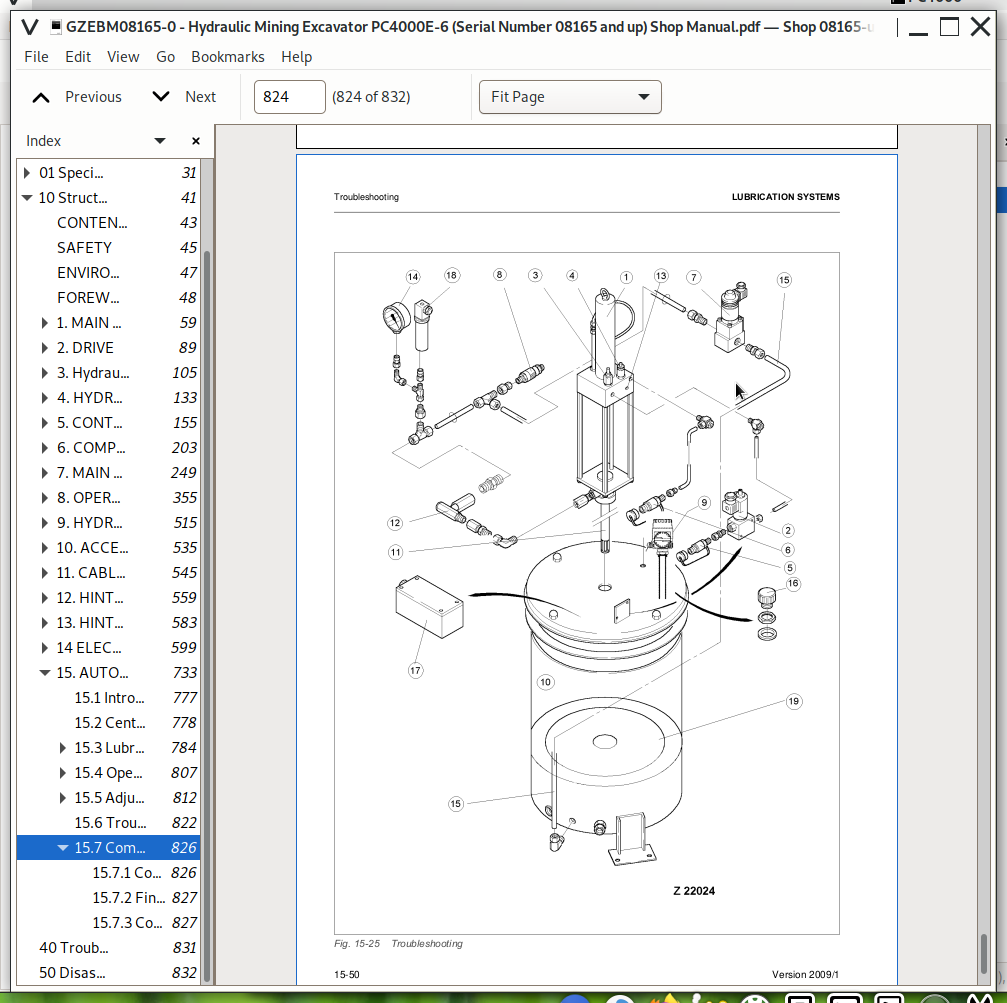
15.6 Troubleshooting.......822
15.7 Commissioning.......826
15.7.1 Commissioning of the CLS.......826
15.7.2 Fine Adjustment.......827
15.7.3 Commissioning of the SLS.......827
40 Troubleshooting.......831
50 Disassembly and Assembly.......832
Komatsu Hydraulic Mining Excavator PC4000 Repair Service Manual
![]()