
John Deere Series 300 Diesel Engines 3029, 4039, 4045, 6059 and 6068 Component Technical Manual (CTM8)
Complete service repair manual with Electrical Wiring Diagrams for John Deere Series 300 3029 (S.N. -499999), 4039, 4045, 6059 and 6068 Diesel Engines, with all the technical information to maintain, diagnose, repair, and rebuild like professional mechanics.
Jonn Deere Series 300 3029 (S.N. -499999), 4039, 4045, 6059 and 6068 Diesel Engines workshop service repair manual includes:
* Numbered table of contents easy to use so that you can find the information you need fast.
* Detailed sub-steps expand on repair procedure information
* Numbered instructions guide you through every repair procedure step by step.
* Troubleshooting and electrical service procedures are combined with detailed wiring diagrams for ease of use.
* Notes, cautions and warnings throughout each chapter pinpoint critical information.
* Bold figure number help you quickly match illustrations with instructions.
* Detailed illustrations, drawings and photos guide you through every procedure.
* Enlarged inset helps you identify and examine parts in detail.
ctm8 - Series 300 3029 (S.N. -499999), 4039, 4045, 6059 and 6068 Diesel Engines Component Technical Manual.pdf
ctm8 - Series 300 3029 (S.N. -499999), 4039, 4045, 6059 and 6068 Diesel Engines Component Technical Manual.epub
PRODUCT DETAILS:
Total Pages: 853 pages
File Format: PDF (bookmarked, ToC, Searchable, Printable, high quality) & EPUB/MOBI/AZW for Kindle/iPad/iPhone/Android.
Language: English
MAIN SECTIONS
ctm8 - Series 300 3029 (S.N. -499999), 4039, 4045, 6059 and 6068 Diesel Engines
Component Technical Manual
Table of Contents
Forward
Engine Identification Views
Section : 3029/4039/4045/6059/6068 Diesel Engines
Group 00: Safety
Handle Fluids Safely—Avoid Fires
Prevent Battery Explosions
Prepare for Emergencies
Prevent Acid Burns
Avoid High-Pressure Fluids
Wear Protective Clothing
Service Machines Safely
Work In Ventilated Area
Work in Clean Area
Remove Paint Before Welding or Heating
Avoid Heating Near Pressurized Fluid Lines
Illuminate Work Area Safely
Use Proper Lifting Equipment
Construct Dealer-Made Tools Safely
Practice Safe Maintenance
Use Proper Tools
Dispose of Waste Properly
Live With Safety
Group 01: General Information
Unified Inch Bolt and Screw Torque Values
Metric Bolt and Screw Torque Values
Engine Model Designation
Engine Serial Number Plate Information
OEM Engine Option Code Label
Engine References
Engine Application ChartJohn Deere Agricultural Equipment
Engine Application Chart John Deere Construction Equipment
Engine Application Chart OEM Applications
Group 02: Fuels, Lubricants and Coolant
Diesel Fuel
Lubricity of Diesel Fuels
Engine Break-In Oil
Diesel Engine Oil
Alternative and Synthetic Lubricants
Mixing of Lubricants
OILSCAN Plus® and COOLSCAN Plus®
Grease
Diesel Engine Coolant Recommendations
Engine Coolant Specifications
Testing Diesel Engine Coolant
Replenishing Supplemental Coolant Additives (SCA’s) Between Coolant Changes
Operating in Warm Temperature Climates
Flush and Service Cooling System
Disposing of Coolant
Group 03: Engine Mounting
Engine Repair Stand
Safety Precautions
Install 300 Series Adapters on Repair Stand
Engine Lifting Procedure
Clean Engine
Mount Engine on Repair Stand
Disconnect Turbocharger Oil Inlet Line
Group 04: Engine Rebuild Guide
Engine Disassembly Sequence
Sealant Application Guidelines
Engine Assembly Sequence
Group 05: Cylinder Head and Valves
Essential Tools
Service Equipment And Tools
Other Material
Cylinder Head and Valves Specifications
Check and Adjust Valve Clearance
Measure Valve Lift
Remove Cylinder Head
Disassemble and Inspect Rocker Arm Assembly
Assemble Rocker Arm Assembly
Inspect, Measure, and Assemble Camshaft Followers
Check Valve Recess In Cylinder Head
Preliminary Cylinder Head and Valve Checks
Remove Valve Assembly
Inspect and Measure Valve Springs
Inspect Valve Rotators
Clean Valves
Inspect and Measure Valves
Grind Valves
Inspect and Clean Cylinder Head
Check Cylinder Head Flatness
Measure Cylinder Head Thickness
Clean Injection Nozzle Bores
Clean Valve Guides
Measure Valve Guides
Knurl Valve Guides
Clean and Inspect Valve Seats
Grind Valve Seats
Remove Valve Seat Inserts
Measure Valve Seat Bore in Cylinder Head
Install Valve Seat Inserts
Install Valves
Clean and Inspect Cylinder Head Cap Screws
Inspect and Clean Exhaust Manifold
Clean and Inspect Top Deck of Cylinder Block
Measure Cylinder Liner Standout (Height Above Block)
Install Cylinder Head
Torque-Turn Method For Proper Torque
Install Rocker Arm Assembly
Inspect and Clean Ventilator Outlet Hose
Install Rocker Arm Cover
Complete Final Assembly
Perform Engine Break-In
Group 10: Cylinder Block, Liners, Pistons and Rods
Essential Tools
Service Equipment And Tools
Other Material
Cylinder Block, Liners, Pistons and Rods Specifications
Remove Pistons and Connecting Rods
Remove Cylinder Liners
Complete Disassembly of Cylinder Block (If Required)
Preliminary Liner, Piston and Rod Checks
Disassemble Piston and Rod Assembly
Clean Pistons
Visually Inspect Pistons
Clean Cylinder Liners
Visually Inspect Cylinder Liners
Check Piston Ring Groove Wear
Measure Piston Pin Bore
Measure Piston Skirt
Measure Piston Height
Determine Piston-to-Liner Clearance
Deglaze Cylinder Liners
Replace Piston and Liner Sets
Inspect and Measure Connecting Rod Bearings (Rods Removed From Engine)
Inspect and Measure Connecting Rod Bearings (Rod and Crankshaft in Engine)
Inspect Rod and Cap
Inspect Piston Pins and Bushings
Remove Piston Pin Bushing
Clean and Inspect Connecting Rod Pin Bore
Install Piston Pin Bushing in Connecting Rod
Measure Rod Center-to-Center Bores
Inspect and Clean Cylinder Block
Clean Cylinder Liner O-Ring Bore
Measure Cylinder Block Main Bearing Bore
Measure Camshaft Follower Bore
Measure Camshaft Bearing Bore
Measure Balancer Shaft Bore—4-Cylinder Engines
Measure Cylinder Block Top Deck Flatness
Measure Liner Flange Counterbore Depth in Block
Measure Liner Flange Thickness
Remove, Inspect and Install Piston Cooling Orifices
Measure Cylinder Liners and Block Bores
Install Steel Ball in Oil Passage of Cylinder Block
Measure Cylinder Liner Standout (Height Above Block)
Install Cylinder Liner O-Rings and Packings
Install Cylinder Liner
Assemble Piston and Connecting Rod
Install Piston Rings
Install Piston and Connecting Rod Assembly
Torque-Turn Connecting Rod Cap Screws
Check Engine Rotation For Excessive Tightness
Measure Piston Protrusion
Cylinder Block Orifices (Saran Engines)
Cylinder Block Orifices
Complete Final Assembly
Group 15: Crankshaft, Main Bearings and Flywheel
Essential Tools
Service Equipment And Tools
Other Material
Crankshaft, Main Bearings and Flywheel Specifications
Crankshaft and Main Bearing Failure Analysis
Inspect Vibration Damper (6-Cylinder Engine)
Remove Pulley or Vibration Damper Pulley (Engine W/O Front PTO)
Install Pulley or Vibration Damper Pulley (Engine W/O Front PTO)
Checking Vibration Damper or Pulley (Engine With Front PTO)
Removing Vibration Damper or Pulley (Engine With Front PTO)
Installing Vibration Damper or Pulley (Engine With Front PTO)
Installing Vibration Damper or Pulley (Engine With Crankshaft Gear-Driven PTO)
Replace Front Crankshaft Oil Seal (Without Removing Timing Gear Cover)
Check Crankshaft End Play
Inspect Flywheel
Check Flywheel Housing Face Runout
Check Flywheel Face Flatness
Check Pilot Bearing Bore Concentricity
Remove Flywheel
Replace Flywheel Ring Gear
Replace Pilot Bearing In Flywheel—3029, 4039, 4045 Engines (If Equipped)
Install Flywheel
Crankshaft Rear Oil Seal and Wear Sleeve General Information
Crankshaft Unitized Rear Oil Seal and Wear Sleeve Handling Precautions
Remove Two-Piece Crankshaft Rear Oil Seal and Wear Sleeve (Without Removing Flywheel Housing)
Remove Unitized (Non-Separable) Crankshaft Rear Oil Seal and Wear Sleeve
Clean and Inspect Crankshaft Flange
Install Crankshaft Rear Oil Seal and Wear Sleeve
Remove Flywheel Housing
Remove Crankshaft Main Bearings
Check Main Bearing Oil Clearance
Remove and Install Crankshaft Gear (Crankshaft Installed In Engine)
Remove Crankshaft
Remove Crankshaft Rear Wear Sleeve (Crankshaft Removed From Engine)
Inspect Crankshaft
Measure Main Bearing ID and Crankshaft Journal OD
Measure Main Thrust Journal Width and Thrust Bearing Width
Crankshaft Grinding Guidelines
Crankshaft Grinding Specifications [Earlier Engines With Ground (Tangential) Fillets (A)]
Crankshaft Grinding Specifications [Later Engines With Undercut and Rolled Fillets (A)]
Measure Assembled ID of Main Bearing Caps
Measure Crankshaft Main Bearing Bore Centerline-To-Top Deck
Inspect Piston Cooling Orifices
Install Main and Thrust Bearing Inserts In Block
Install Crankshaft
Install Flywheel Housing
Complete Final Assembly
Group 16: Camshaft, Balancer Shafts and Timing Gear Train
Essential Tools
Service Equipment And Tools
Other Material
Camshaft, Balancer Shafts and Timing Gear Train Specifications
Measure Valve Lift
Remove Timing Gear Cover
Remove and Install Camshaft Bushing With Front Plate Installed Camshaft Gear-Driven Auxiliary Drive Engines, Saran Built Engines Serial No. (138541—)
Remove Auxiliary Drive Gears (Engines With Auxiliary Gear Drive Option)
Measure Camshaft End Play
Measure Balancer Shaft End Play (4-Cylinder Engines)
Measure Idler Gear End Play
Measure Timing Gear Backlash
Remove Camshaft
Visually Inspect Camshaft
Measure Camshaft Thrust Plate Clearance and Thickness
Inspect and Measure Camshaft Bearing Bore ID and Journal OD
Measure Camshaft Lobe Height
Remove and Install Camshaft Gear
Inspect Camshaft Followers
Replace Tachometer Drive Gear
Remove and Install Camshaft Bushing With Front Plate Removed Engine Serial No. ( —138540)
Remove Balancer Shafts—If Equipped (4-Cylinder Engines)
Inspect and Measure Balancer Shaft Bushings and Journals
Remove and Install Balancer Shaft Bushings (4-Cylinder Engines)
Install Oversize Balancer Shaft Bushings In Cylinder Block (4039 Engines)
Inspect Balancer Shaft Gears and Thrust Plates
Remove and Install Balancer Shaft Gears
Remove Cylinder Block Front Plate
Measure Idler Gear Bushing and Shaft
Remove and Install Idler Gear Bushings
Remove Lower and Upper Idler Shafts
Clean and Inspect Front Plate
Replace Engine Front Plate
Transfer Fuel Injection Pump Timing Mark Onto Replacement Front Plate
Install Idler Shaft Spring Pins (If Equipped)
Install Upper Idler Shaft In Front Plate
Install Lower Idler Shaft In Front Plate
Install Engine Front Plate
Install and Time Balancer Shafts—If Equipped (4-Cylinder Engines)
Install and Time Camshaft and Fuel Injection Pump
Clean and Inspect Timing Gear Cover
Install Ball Bearings and Dowels (Engines With Crankshaft-Driven Auxiliary Gear Drive Option)
Install Drive Gear (Engines With Crankshaft-Driven Auxiliary Gear Drive Option)
Install Timing Gear Cover
Install Idler Gear and Output Gear (Engines With Auxiliary Gear Drive Option)
Complete Final Assembly
Group 20: Lubrication System
Essential Tools
Service Equipment And Tools
Other Material
Lubrication System Specifications
General Lubrication System Information
Oil Cooler Identification
Remove, Inspect, and Install Standard-Flow Oil Cooler
Remove and Install High-Flow Oil Cooler
Replacing Standard Oil Cooler/Oil Filter Housings
Replace Oil Filter Adapter on Engine With Remote Oil Filter
Remove, Inspect, and Install Oil Bypass Valve—3029, 4039, and 6059 Engines and 4045 and 6068 Engines With Common Lube Block See GENERAL LUBRICATION SYSTEM INFORMATION earlier in this group for an explanation of "Common-Lube" blocks.
Remove and Install Oil Bypass Valve—4045 and 6068 Engines With Pre-Common Lube Block See GENERAL LUBRICATION SYSTEM INFORMATION earlier in this group for an explanation of "Common-Lube" blocks.
Remove and Install Oil Pressure Regulating Valve and Seat—3029, 4039, and 6059 Engines and 4045 and 6068 Engines With Common Lube Block See GENERAL LUBRICATION SYSTEM INFORMATION earlier in this group for an explanation of "Common-Lube" blocks.
Remove, Inspect, and Install Oil Pressure Regulating Valve—4045 and 6068 Engines With Pre-Common Lube Block See GENERAL LUBRICATION SYSTEM INFORMATION earlier in this group for an explanation of "Common-Lube" blocks.
Remove and Install Oil Filter Nipple—3029, 4039, 6059 Engines
Remove and Install Oil Pan Mounted Oil Fill/Dipstick Tube
Remove, Install, and Adjust Dipstick Nipple
General Oil Pump Information
Remove, Inspect and Install Oil Pump Pick-Up Tube Assembly
Remove Standard Capacity Oil Pump
Inspect and Measure Clearances (Standard Capacity Oil Pump)
Complete Standard Capacity Oil Pump Disassembly
Assemble Standard Capacity Oil Pump
Install Standard Capacity Oil Pump
Remove High Capacity Oil Pump
Inspect and Measure Clearances (High Capacity Oil Pump)
Complete High Capacity Oil Pump Disassembly
Assemble High Capacity Oil Pump
Install High Capacity Oil Pump
Install Oil Pan
Group 25: Cooling System
Essential Tools
Service Equipment And Tools
Other Material
Cooling System Specifications
Remove, Test, and Install Thermostats
Remove and Install Water Manifold/Thermostat Housing
General Water Pump Information
Remove Water Pump
Disassemble Low Flow, Standard-Duty High Flow, and Modular Style Water Pumps
Disassemble Heavy-Duty High Flow Water Pump
Inspect and Clean Water Pump Parts
Assemble Low Flow, Standard-Duty High Flow, and Modular Style Water Pumps
Assemble Heavy-Duty High Flow Water Pump
Pulley or Hub-to-Rear Face of Water Pump Housing Dimensions
Check Water Pump Cap Screw Protrusion
Install Water Pump
Cooling System Deaeration
Inspect and Install Fan Blade Assembly
Adjust Fan Belt Tension
Remove and Install Coolant Heater (Dubuque-Built Engines)—If Equipped
Remove and Install Coolant Heater (Saran-Built Engines)—If Equipped
Group 30: Air Intake and Exhaust System
Other Material
Air Intake and Exhaust System Specifications
Extending Turbocharger Life
Remove Turbocharger
Turbocharger Failure Analysis
Turbocharger Seven-Step Inspection
Perform Radial Bearing Clearance Test
Perform Axial Bearing End Play Test
Repair Turbocharger
Disassemble and Inspect Turbocharger
Replace Center Housing and Rotating Assembly
Prelube Turbocharger
Install Turbocharger
Turbocharger Break-In
Recommendations for Turbocharger Use
Remove, Inspect and Install Intake Manifold
Remove, Inspect and Install Exhaust Manifold
Aftercooler Assembly
Remove and Install Aftercooler
Inspect and Repair Aftercooler
Group 35: Fuel System
Essential Tools
Service Equipment and Tools
Other Material
Fuel System Specifications
Fuel System—General Information
Relieve Fuel System Pressure
Replace Primary Fuel Filter/Water Separator and Final Fuel Filter Assemblies
Primary Fuel Filter/Water Separator Assembly
Final Fuel Filter Assembly
Replace Rectangular Fuel Filter Element
Replace Round Fuel Filter Element (Early Model Engines)
Replace Final Fuel Filter and Primary Fuel Filter/Water Separator Elements (Later Engines)
Remove Fuel Supply Pump
Bench Test Fuel Supply Pump
Install Fuel Supply Pump
Fuel Injection Pump Timing
Remove Stanadyne Model DB2 Injection Pump With Non-Retained Drive Shaft
Repair Stanadyne Fuel Injection Pump
Remove Stanadyne DB2 Non-Retained Injection Pump Drive Shaft From Engine
Install Non-Retained Drive Shaft In Stanadyne DB2 Injection Pump (If Removed from Engine)
Install Stanadyne Model DB2 Injection Pump With Non-Retained Drive Shaft
Remove Stanadyne Model DB2 (With Retained Drive Shaft) and DB4 Injection Pump
Inspect Injection Pump Drive Gear I.D. and Shaft O.D.
Repair Stanadyne Fuel Injection Pump
Install Stanadyne Model DB2 (With Retained Drive Shaft) and DB4 Injection Pump
Remove Stanadyne Model DM4 Fuel Injection Pump
Repair Stanadyne Fuel Injection Pump
Install Stanadyne Model DM4 Fuel Injection Pump
Remove Lucas CAV Fuel Injection Pump
Repair Lucas CAV Fuel Injection Pump
Install Lucas CAV Fuel Injection Pump
Aneroid Replacement
Aneroid Field Adjustment
Aneroid Workshop Adjustment
Replace Engine Front Plate
Transfer Fuel Injection Pump Timing Mark Onto Replacement Front Plate
Remove Fuel Injection Nozzles
Clean Fuel Injection Nozzle Bore
Clean Injection Nozzles
Diagnose Fuel Injection Nozzle Malfunction
Test Fuel Injection Nozzles
Disassemble Injection Nozzles
Inspect and Clean Nozzle Body
Inspect and Clean Valve and Valve Seat
Inspect Valve Adjusting Mechanism
Assemble Injection Nozzles
Adjust Fuel Injection Nozzles
Install Seals on Injection Nozzle
Install Injection Nozzles
Group 40: Starting and Charging Systems
Essential Tools
Remove and Install Starter
Remove and Install Alternator
Group 100: Engine Tune-Up and Break-In
Effects of Altitude and Temperature on Engine Performance
Preliminary Engine Testing
General Tune-Up Recommendations
Dynamometer Test
Dynamometer Test Specifications
Engine Break-In Guidelines
Perform Engine Break-In
Engine Oil Consumption
Check Crankcase Ventilation System
Check Air Intake System
Check Exhaust System
Check and Service Cooling System
Check Electrical System
Group 105: Engine System Operation and Tests
Essential Tools
Engine Test Specifications
Engine—Sectional View
General Engine Description
How the Engine Lubrication System Works
How the Cooling System Works
How the Crankshaft Gear-Driven Auxiliary Drive Works
Head Gasket Joint Construction and Operation
Diagnosing Head Gasket Joint Failures
Head Gasket Inspection and Repair Sequence
Diagnosing Engine Malfunctions
Test Engine Compression Pressure
Check Engine Oil Pressure
Measure Engine Crankcase Pressure (Blow-By)
Pressure Test Cooling System and Radiator Cap
Inspect Thermostat and Test Opening Temperature
Engine Cranking Speed Test
Group 110: Air Intake and Exhaust System Operation and Tests
Essential Tools
Service Equipment and Tools
Air Intake System Test Specifications
Diagnosing Air Intake Malfunctions
How the Air Intake and Exhaust System Works
Air Cleaner Operation
Air Filter Restriction Indicator Switch Test
Intake Air Leak Test
Exhaust Leak Check (Turbocharged Engines)
Intake and Exhaust Restriction Check
Diagnosing Turbocharger Malfunctions
Turbocharger Operation
How the Turbocharger is Lubricated
Check Intake Manifold Pressure (Turbocharger Boost)
Turbocharger Oil Seal Leak Test
Group 115: Fuel System Operation and Tests
Essential Tools
Service Equipment And Tools
Fuel System Test Specifications
Fuel Injection Pump Specifications
Using TIME TRAC TIME TRAC is a registered trademark of Stanadyne Automotive Corp. as a Tachometer
Check and Adjust Rotary Injection Pump Dynamic Timing
Fuel System Operation
Diagnose Fuel System Malfunctions
Fuel Supply Quality Check
Air in Fuel Test
Restricted Fuel Return Line Check
Fuel Supply Pump Operation—If Equipped
Diagnose Fuel Supply Pump Malfunctions
Measure Fuel Supply Pump Pressure
Fuel Shut-Off Solenoid Resistance Test (Lucas Pump)
Rectangular Final Fuel Filter Operation
Round (Primary) Fuel Filter/Water Separator Operation
Final Fuel Filter/Water Separator Operation
Bleed the Fuel System
Stanadyne Fuel Injection Pump Operation
Lucas CAV Fuel Injection Pump Operation
Diagnose Rotary Fuel Injection Pump Malfunctions
Check and Adjust Engine Speeds on Lucas CAV Pump
Adjust Variable Speed on Generator Set Engines (Lucas CAV Pumps Only)
Check and Adjust Engine Speeds on Stanadyne Pump
Adjust Variable Speed (Droop) on Generator Set Engines (3—5% Govenor Regulation)—Stanadyne DB2, DB4, DM4 Injection Pumps
Changing Gen Set Engine Rated Speed from 1800 RPM to 1500 RPM—Stanadyne DB2, DB4, DM4 Injection Pumps
Diagnose Aneroid Malfunctions
Fuel Injection Nozzles—General Information and Operation
Diagnose Fuel Injection Nozzle Malfunctions
Test Fuel Injection Nozzles (Engine Running)
Fuel Drain Back Test Procedure
Group 199: Dealer Fabricated Tools
How to Make Tools
DFRG2—Injection Pump Front Plate Timing Mark Transfer Tool
DFRG3—Cylinder Liner Holding Fixture
John Deere Series 300 Diesel Engines 3029, 4039, 4045, 6059 and 6068 Component Technical Manual (CTM8)
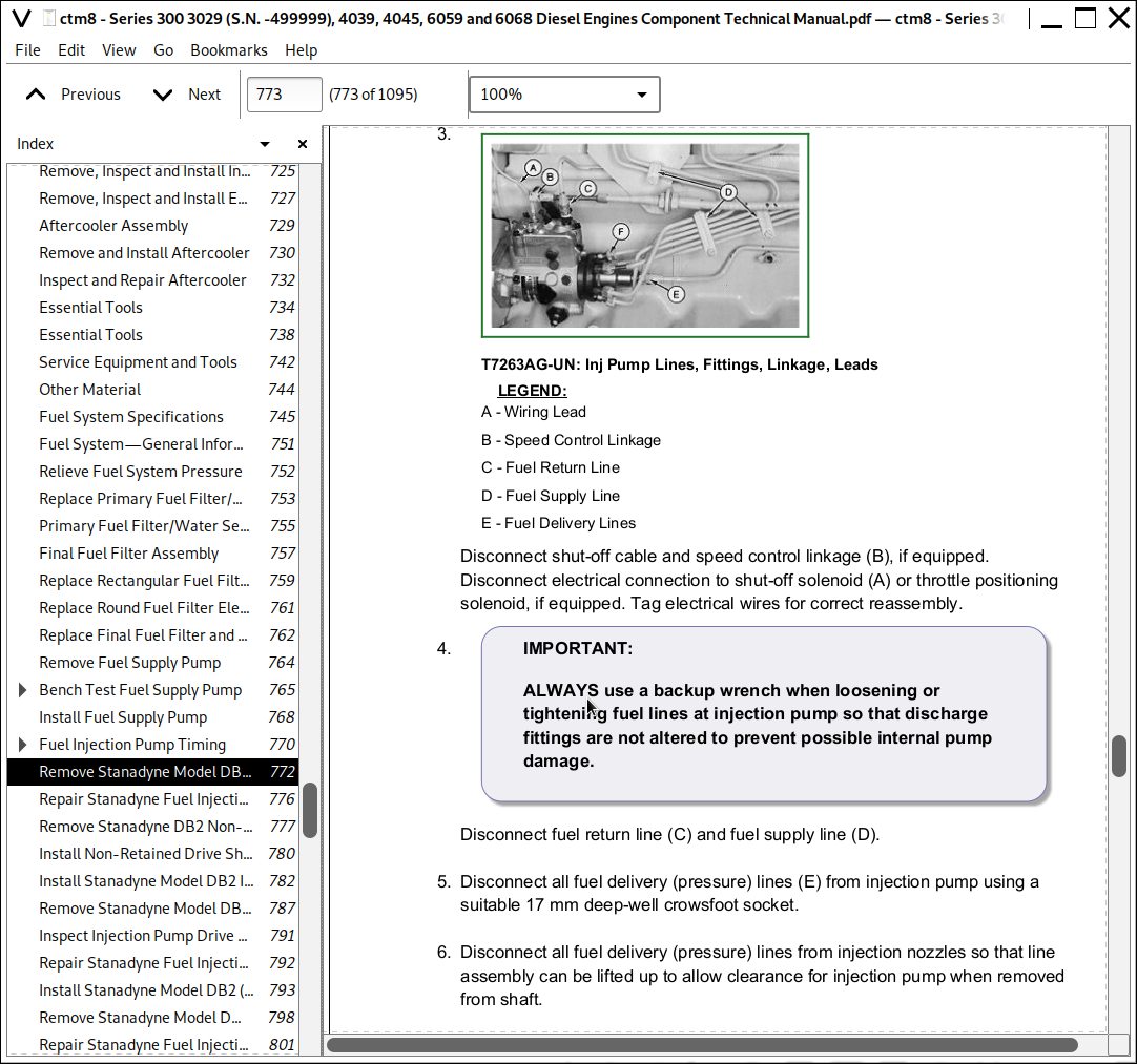
![]()