
Audi A4 All Models Repair Service Manual MY2008-2016
Complete service repair manual with Electrical Wiring Diagrams for Audi A4 Petrol & Diesel Models, with all the technical information to maintain, diagnose, repair, rebuild like professional mechanics.
2008-2016 Audi A4 All Models workshop service repair manual includes:
* Numbered table of contents easy to use so that you can find the information you need fast.
* Detailed sub-steps expand on repair procedure information
* Numbered instructions guide you through every repair procedure step by step.
* Troubleshooting and electrical service procedures are combined with detailed wiring diagrams for ease of use.
* Notes, cautions and warnings throughout each chapter pinpoint critical information.
* Bold figure number help you quickly match illustrations with instructions.
* Detailed illustrations, drawings and photos guide you through every procedure.
* Enlarged inset helps you identify and examine parts in detail.
PRODUCT DETAILS:
Total Pages: 11,085 pages
File Format: PDF (Internal Links, Bookmarked, Table of Contents, Searchable, Printable, high quality)
Language: English
4-cylinder direct petrol injection engine (1.8 ltr., 2.0 ltr. 4-valve turbo), mechanics - Audi A4 2008 ➤, Audi A5 Cabriolet 2009 ➤, Audi A5 Coupé 2008 ➤.pdf
4-cylinder TDI engine (2.0 ltr. 4-valve common rail - generation II), mechanics - Audi A4 2008 ➤, Audi A5 Coupé 2008 ➤.pdf
6-cylinder direct petrol injection engine (3.2 ltr. 4-valve), mechanics - Audi A4 2008 ➤, Audi A5 Cabriolet 2009 ➤, Audi A5 Coupé 2008 ➤.pdf
6-cylinder direct petrol injection engine with supercharger (3.0 ltr. 4-valve), mechanics - Audi A4 2008 ➤, Audi A5 Cabriolet 2009 ➤, Audi A5 Coupé 2008 ➤.pdf
6-cylinder TDI engine (2.7 ltr.; 3.0 ltr. 4-valve common rail), mechanics - A4 2008 ➤, A5 Cabriolet 2009 ➤, A5 Coupé 2008 ➤, A5 Sportback 2010 ➤.pdf
6-speed manual gearbox 0B1, front-wheel drive - Audi A4 2008 ➤, Audi A5 Cabriolet 2009 ➤, Audi A5 Coupé 2008 ➤.pdf
6-speed manual gearbox 0B2, four-wheel drive - Audi A4 2008 ➤, Audi A5 Coupé 2008 ➤.pdf
6-speed manual gearbox 0B3, front-wheel drive - Audi A4 2008 ➤, Audi A5 Cabriolet 2009 ➤, Audi A5 Coupé 2008 ➤.pdf
6-speed manual gearbox 0B4, four-wheel drive - Audi A4 2008 ➤, Audi A5 Coupé 2008 ➤.pdf
Air conditioners with refrigerant R1234yf - General information - Audi models.pdf
Air conditioner with refrigerant R134a - Audi Models.pdf
Automatic gearbox 0B6, four-wheel drive - Audi A4 2008 ➤, Audi A5 Cabriolet 2009 ➤, Audi A5 Coupé 2008 ➤.pdf
Auxiliary heater - Audi A4 2008 ➤ Audi A5 Coupé 2008 ➤ Audi A5 Sportback 2010 ➤.pdf
Body Repairs - Audi A4 2008 ➤.pdf
Brake system - Audi A4 2008 ➤.pdf
Direct petrol injection and ignition system (4- cylinder 1.8 ltr.4-valve turbo with timing chain) - Audi A4 2008 ➤, Audi A5 Cabriolet 2009 ➤, Audi A5 Coupé 2008 ➤.pdf
Direct petrol injection and ignition system (4- cylinder 2.0 ltr. 4-valve turbo with timing chain) - Audi A4 2008 ➤, Audi A5 Cabriolet 2009 ➤, Audi A5 Coupé 2008 ➤.pdf
Electrical Equipment General Information - Audi Models.pdf
Electrical system (Audi A4 2008 ➤).pdf
Electrical Wiring Diagrams.pdf
Fitting instructions- radio communication systems.pdf
Fitting instructions, retrofitting key-operated switch to deactivate airbag on front passenger side - Audi Models.pdf
Fuel supply system, diesel engines - Audi A4 2008 ➤, Audi A5 Cabriolet 2009 ➤, Audi A5 Coupé 2008 ➤, Audi A5 Sportback 2010 ➤.pdf
Fuel supply system, petrol engines - Audi A4 2008 ➤, Audi A5 Cabriolet 2009 ➤, Audi A5 Coupé 2008 ➤.pdf
General body Protected repairs, exterior (Audi A4 2008 ➤, Audi A4 Avant 2008 ➤).pdf
General body repairs, interior - Audi A4 2008 ➤.pdf
General InformationBody Repairs, General Body Repairs - Audi Models.pdf
Maintenance - Audi A4 2008 ➤.pdf
multitronic 0AW, front-wheel drive - Audi A4 2008 ➤, Audi A5 Cabriolet 2009 ➤, Audi A5 Coupé 2008 ➤.pdf
Radio Installation Instructions - Audi Models.pdf
Rear final drive 0BC, 0BD, 0BE, 0BF - Audi A4 2008 ➤ , Audi A5 Cabriolet 2009 ➤ , Audi A5 Coupé 2008 ➤ , Audi A6 2011 ➤ , Audi A6 China 2012 ➤ , Audi A7 Sportback 2011 ➤ , Audi A8 2010 ➤ , Audi Q5 2008 ➤ , Audi Q5 China 2010 ➤.pdf
Rear final drive 0BC - Audi A4 2008 ➤ , Audi A5 Cabriolet 2009 ➤ , Audi A5 Coupé 2008 ➤ , Audi A6 2011 ➤ , Audi A7 Sportback 2011 ➤ , Audi A8 2010 ➤ , Audi Q5 2008 ➤.pdf
Rear final drive 0BD - Audi A4 2008 ➤, Audi A5 Cabriolet 2009 ➤, Audi A5 Coupé 2008 ➤, Audi Q5 2008 ➤.pdf
Rear final drive 0BF and 0BE - sport differential - Audi A4 2008 ➤ , Audi A5 Cabriolet 2009 ➤ , Audi A5 Coupé 2008 ➤ , Audi A6 2011 ➤ , Audi A7 Sportback 2011 ➤ , Audi A8 2010 ➤.pdf
Rear final drive 0BF and 0BE – sport differential - Audi A4 2008 ➤ , Audi A5 Cabriolet 2009 ➤ , Audi A5 Coupé 2008 ➤ , Audi A6 2011 ➤ , Audi A6 China 2012 ➤ , Audi A7 Sportback 2011 ➤ , Audi A8 2010 ➤.pdf
Refrigerant R134a Servicing - Audi Models.pdf
Running gear, front-wheel drive and four-wheel drive - Audi A4 2008 ➤.pdf
Servicing 4-cyl. engine, 2.0 ltr. 4-valve TFSI (EA 888, Gen. III).pdf
Servicing 4-cylinder engine, 1.8 ltr., 2.0 ltr. 4-valve TFSI (EA 888, Gen. II) - A4 2008 ➤, A5 Cabriolet 2009 ➤, A5 Coupé 2008 ➤, A6 2011 ➤, A6 China 2012 ➤, A8 2010 ➤, Q5 2008 ➤, Q5 China 2010 ➤.pdf
Servicing 6-speed manual gearbox 0B1, front-wheel drive - Audi A4 2008 ➤ , Audi A5 Cabriolet 2009 ➤ , Audi A5 Coupé 2008 ➤ , Audi A6 2011 ➤ , Audi A6 China 2012 ➤ , Audi Q5 2008 ➤.pdf
Servicing 6-speed manual gearbox 0B1, front-wheel drive - Audi A4 2008 ➤ , Audi A5 Cabriolet 2009 ➤ , Audi A5 Coupé 2008 ➤ , Audi A6 2011 ➤ , Audi Q5 2008 ➤.pdf
Servicing 6-speed manual gearbox 0B2, four-wheel drive - Audi A4 2008 ➤, Audi A5 Cabriolet 2009 ➤, Audi A5 Coupé 2008 ➤, Audi Q5 2008 ➤.pdf
Servicing 6-speed manual gearbox 0B3, front-wheel drive - Audi A4 2008 ➤, Audi A5 Cabriolet 2009 ➤, Audi A5 Coupé 2008 ➤.pdf
Servicing 6-speed manual gearbox 0B4, four-wheel drive - Audi A4 2008 ➤, Audi A5 Coupé 2008 ➤.pdf
Servicing 7-speed dual clutch gearbox 0B5 (S tronic) - Audi A4 2008 ➤ , Audi A5 Cabriolet 2009 ➤ , Audi A5 Coupé 2008 ➤ , Audi A6 2011 ➤ , Audi A6 China 2012 ➤ , Audi A7 Sportback 2011 ➤ , Audi Q5 2008 ➤ , Audi Q5 China 2010 ➤.pdf
Servicing 7-speed dual clutch gearbox 0CJ,0CL,0CK,0DN,0DP,0HL - A4,A4 Avant,A4 China,A4 allroad quattro 2015➤,A5 2016➤,A6,A6 Avant,A6 China 2012 2011-2019➤,A7 Sportback,Sportback USA 2011-2018➤,Q5 2008-2017➤,Q5 China 2019 ➤.pdf
Servicing 8-speed automatic gearbox - A4 2008-2015-2016➤ ,A5 Cabriolet 2009➤ ,A5 Coupé 2008➤,A6,A6 China 2011-2019➤ ,A7 Sportback 2011-2018➤ ,A8 2010➤,A8,A8 China 2018➤,Q5 2008-2017➤,Q5 China 2010➤ ,Q7 2016➤.pdf
Servicing multitronic 0AW - Audi A4 2008 ➤ , Audi A5 Cabriolet 2009 ➤ , Audi A5 Coupé 2008 ➤ , Audi A6 2011 ➤ , Audi A6 China 2012 ➤ , Audi A7 Sportback 2011 ➤.pdf
Servicing multitronic 0AW - Audi A4 2008 ➤ , Audi A5 Cabriolet 2009 ➤ , Audi A5 Coupé 2008 ➤ , Audi A6 2011 ➤ , Audi A7 Sportback 2011 ➤.pdf
Simos direct petrol injection and ignition system (6- cylinder 3.0 ltr. TFSI 4-valve) - Audi A4 2008 ➤, Audi S5 Cabriolet 2010 ➤, Audi S5 Coupé 2008 ➤.pdf
Simos direct petrol injection and ignition system (6- cylinder 3.2 ltr. 4-valve) - Audi A4 2008 ➤.pdf
Specifications for testing the braking force (accordingto German legislation) - Audi models.pdf
System description - adaptive cruise control - Audi A4 2008 ➤, Audi A5 Cabriolet 2009 ➤, Audi A5 Coupé 2008 ➤.pdf
System description - dynamic steering - Audi A4 2008 ➤.pdf
System description - entry and start authorisation - Audi A4 2008 ➤, Audi A5 Cabriolet 2009 ➤, Audi A5 Coupé 2008 ➤, Audi Q5 2008 ➤.pdf
System description - exterior lights - Audi A4 2008 ➤, Audi Q5 2008 ➤.pdf
System description - infotainment and audio output (MOST) - Audi A4 2008 ➤, Audi A5 Cabriolet 2009 ➤, Audi A5 Coupé 2008 ➤.pdf
System description - infotainment and navigation system - Audi A4 2008 ➤, Audi A5 Cabriolet 2009 ➤, Audi A5 Coupé 2008 ➤.pdf
System description - interior lights - Audi A4 2008 ➤, Audi Q5 2008 ➤.pdf
System description - lane change assist (Audi side assist) - Audi A4 2008 ➤, Audi A5 Coupé 2008 ➤.pdf
System description - lane departure warning (Audi lane assist) - Audi A4 2008 ➤, Audi A5 Coupé 2008 ➤.pdf
System description - steering wheel - Audi A4 2008 ➤.pdf
System description - Windows and doors - Audi A4 2008 ➤.pdf
System description - wiper and washer systems - Audi A4 2008 ➤, Audi Q5 2008 ➤.pdf
TDI injection and glow plug system (4- cylinder 2.0 ltr. 4-valve common rail) - Audi A4 2008 ➤, Audi A5 Cabriolet 2009 ➤, Audi A5 Coupé 2008 ➤.pdf
Towing Guide - Audi models.pdf
Trailer Operation Guide - Audi models.pdf
Wheels and tyres - Audi Models.pdf
Wheel & Tire General Information - Audi Models.pdf
Wheel_Tyre Guide - Audi A4 2008 ➤, Audi A4 2015 ➤.pdf
MAIN SECTIONS
4-cylinder TDI engine (2.0 ltr. 4-valve common rail - generation II), mechanics - Audi A4 2008 >, Audi A5 Coup> 2008 >.......7
00 > Technical data.......13
1 Engine number.......13
2 Engine data.......14
3 Safety precautions.......15
3.1 Working on the fuel system.......15
3.2 Working on the cooling system.......16
3.3 Working on vehicles with start/stop system.......16
3.4 Using testers and measuring instruments during a road test.......17
3.5 Working on the exhaust system.......17
3.6 Working on the subframe.......17
4 General repair instructions.......18
4.1 Rules for cleanliness when working on fuel supply system, injection system and turbocharger.......18
4.2 Checking for leaks in the fuel system.......18
4.3 Foreign particles in engine.......19
4.4 Contact corrosion!.......19
4.5 Routing and attachment of pipes, hoses and wiring.......19
4.6 Installing radiators, condensers and charge air coolers.......19
4.7 Checking vacuum system.......19
10 > Removing and installing engine.......21
1 Removing engine.......21
2 Securing engine to engine and gearbox support.......38
3 Installing engine.......39
4 Assembly mountings.......45
4.1 Assembly mountings - exploded view.......45
4.2 Removing and installing engine mountings.......46
4.3 Removing and installing torque reaction support and cross member.......49
13 > Crankshaft group.......50
1 Cylinder block (pulley end).......50
1.1 Poly V-belt drive - exploded view.......50
1.2 Removing and installing poly V-belt.......52
1.3 Removing and installing tensioner for poly V-belt.......54
1.4 Removing and installing vibration damper.......54
1.5 Removing and installing bracket for ancillaries.......55
1.6 Sealing flange (pulley end) - exploded view.......58
1.7 Renewing crankshaft oil seal (pulley end).......58
1.8 Removing and installing sealing flange (pulley end).......60
2 Cylinder block (gearbox end).......64
2.1 Sealing flange (gearbox end) and drive plate - exploded view.......64
2.2 Removing and installing drive plate.......65
2.3 Removing and installing needle bearing in drive plate.......66
2.4 Renewing sealing flange (gearbox end).......67
3 Crankshaft.......76
3.1 Crankshaft - exploded view.......76
3.2 Crankshaft dimensions.......77
3.3 Measuring axial clearance of crankshaft.......77
3.4 Measuring radial clearance of crankshaft.......78
3.5 Pulling spur gear off crankshaft and shrink-fitting new spur gear.......78
4 Pistons and conrods.......81
4.1 Pistons and conrods - exploded view.......81
4.2 Measuring piston projection at >TDC>.......85
4.3 Piston and cylinder dimensions.......86
4.4 Measuring radial clearance of conrods.......86
15 > Cylinder head, valve gear.......88
1 Toothed belt drive.......88
1.1 Toothed belt drive - exploded view.......88
1.2 Removing and installing toothed belt.......90
2 Cylinder head.......99
2.1 Cylinder head cover - exploded view.......99
2.2 Removing and installing cylinder head cover.......100
2.3 Renewing injector seals.......103
2.4 Cylinder head - exploded view.......105
2.5 Removing and installing cylinder head.......107
2.6 Checking compression.......116
3 Valve gear.......119
3.1 Valve gear - exploded view.......120
3.2 Measuring axial clearance of camshafts.......121
3.3 Measuring radial clearance of camshafts.......122
3.4 Renewing camshaft oil seal.......122
3.5 Removing and installing camshafts.......125
3.6 Checking hydraulic valve compensation elements.......130
3.7 Renewing valve stem oil seals with cylinder head installed.......131
3.8 Renewing valve stem oil seals with cylinder head removed.......135
3.9 Valve dimensions.......138
3.10 Machining valve seats.......138
3.11 Checking valve guides.......138
3.12 Checking valves.......139
17 > Lubrication.......140
1 Sump, oil pump, balance shaft assembly.......140
1.1 Sump, oil pump, balance shaft assembly - exploded view.......141
1.2 Removing and installing oil level and oil temperature sender -G266-.......143
1.3 Removing and installing sump.......143
1.4 Removing and installing oil pump.......146
1.5 Removing balance shaft assembly.......147
1.6 Installing a new balance shaft assembly.......148
1.7 Re-installing a used balance shaft assembly.......151
2 Oil filter bracket, engine oil cooler and oil supply line.......153
2.1 Oil filter bracket and engine oil cooler - exploded view.......153
2.2 Removing and installing oil filter bracket with engine oil cooler.......154
2.3 Removing and installing engine oil cooler.......156
2.4 Removing and installing oil pressure switch -F1-.......157
2.5 Checking oil pressure switch -F1-.......158
2.6 Checking oil pressure.......159
2.7 Engine oil.......160
2.8 Checking oil level.......160
19 > Cooling.......161
1 Cooling system.......161
1.1 Diagram of coolant hose connections.......161
1.2 Draining and filling cooling system.......164
1.3 Checking cooling system for leaks.......170
2 Coolant pump and 4/2-way valve with thermostat.......172
2.1 Coolant pump and 4/2-way valve with thermostat - exploded view.......172
2.2 Removing and installing coolant pump.......173
2.3 Removing and installing 4/2-way valve with thermostat.......173
2.4 Checking thermostat.......176
3 Coolant pipes, coolant temperature senders, coolant circulation pump.......177
3.1 Coolant pipes, coolant temperature senders, coolant circulation pump - exploded view.......178
3.2 Removing and installing coolant temperature sender -G62-.......179
3.3 Removing and installing radiator outlet coolant temperature sender -G83-.......180
3.4 Removing and installing coolant pipe (top left).......181
3.5 Removing and installing coolant pipe (bottom left).......182
3.6 Removing and installing coolant pipe (rear right).......184
3.7 Removing and installing coolant pipe (rear).......186
3.8 Pump for exhaust gas recirculation cooler -V400- - exploded view.......189
3.9 Removing and installing pump for exhaust gas recirculation cooler -V400-.......189
3.10 Continued coolant circulation pump -V50- - exploded view.......192
3.11 Removing and installing coolant circulation pump -V50-.......192
4 Radiator and radiator fan.......194
4.1 Radiator and radiator fan - exploded view.......195
4.2 Removing and installing radiator with radiator cowl - Audi A4.......196
4.3 Removing and installing radiator - Audi A5.......200
4.4 Removing and installing radiator cowl - Audi A5.......203
4.5 Removing and installing radiator fan control unit -J293-.......208
4.6 Removing and installing radiator fan -V7-.......208
21 > Turbocharging/supercharging.......210
1 Turbocharger.......210
1.1 Diagram of vacuum connections.......210
1.2 Turbocharger - exploded view.......212
1.3 Removing and installing turbocharger.......213
2 Charge air cooling.......219
2.1 Charge air cooler - exploded view.......220
2.2 Removing and installing charge air cooler.......221
2.3 Removing and installing charge pressure sender -G31- / intake air temperature sender -G42-.......223
2.4 Checking charge air system for leaks.......223
26 > Exhaust system.......227
1 Silencers.......227
1.1 Silencers - exploded view.......228
1.2 Removing and installing front exhaust pipe.......230
1.3 Removing and installing particulate filter.......231
1.4 Separating centre and rear silencers.......232
1.5 Renewing tailpipes.......233
1.6 Stress-free alignment of exhaust system.......234
1.7 Checking exhaust system for leaks.......235
2 Exhaust manifold.......237
2.1 Exhaust manifold - exploded view.......237
2.2 Removing and installing exhaust manifold.......238
3 Exhaust gas temperature control.......240
3.1 Exhaust gas temperature senders - exploded view.......240
3.2 Removing and installing exhaust gas temperature sender>1 -G235-.......241
3.3 Removing and installing exhaust gas temperature sender>3 -G495-.......243
3.4 Removing and installing exhaust gas temperature sender>4 -G648-.......244
4 Exhaust gas recirculation.......247
4.1 Diagram of vacuum connections.......247
4.2 Exhaust gas recirculation system - exploded view.......247
4.3 Checking exhaust gas recirculation cooler change-over.......248
4.4 Removing and installing exhaust gas recirculation cooler.......248
4-cylinder direct petrol injection engine (1.8 ltr., 2.0 ltr. 4-valve turbo), mechanics - Audi A4 2008 >, Audi A5 Cabriolet 2009 >, Audi A5 Coup> 2008 >.......252
00 > Technical data.......258
1 Engine number.......258
2 Engine data.......259
3 Safety precautions.......261
3.1 Working on the fuel system.......261
3.2 Procedure before opening high-pressure section of injection system.......261
3.3 Working on the cooling system.......262
3.4 Working on vehicles with start/stop system.......262
3.5 Using testers and measuring instruments during a road test.......263
3.6 Working on the exhaust system.......263
3.7 Working on the subframe.......263
4 General repair instructions.......264
4.1 Rules for cleanliness when working on fuel supply system, injection system and turbocharger.......264
4.2 Checking fuel system for leaks.......264
4.3 Foreign particles in engine.......264
4.4 Contact corrosion!.......264
4.5 Routing and attachment of pipes, hoses and wiring.......265
4.6 Checking vacuum system.......265
4.7 Installing radiators, condensers and charge air coolers.......265
10 > Removing and installing engine.......267
1 Removing engine.......267
2 Securing engine to assembly stand.......281
3 Installing engine.......283
4 Supporting engine with support bracket.......289
5 Assembly mountings.......290
5.1 Assembly mountings - exploded view.......290
5.2 Removing and installing engine mountings.......290
13 > Crankshaft group.......293
1 Cylinder block (pulley end).......293
1.1 Poly V-belt drive, bracket for ancillaries - exploded view.......293
1.2 Removing and installing poly V-belt.......295
1.3 Removing and installing tensioner for poly V-belt.......296
1.4 Removing and installing bracket for ancillaries.......297
1.5 Removing and installing vibration damper.......300
2 Cylinder block (gearbox end).......303
2.1 Sealing flange and drive plate - exploded view.......303
2.2 Removing and installing drive plate.......304
2.3 Removing and installing drive plate in needle bearing - vehicles with manual gearbox.......305
2.4 Removing and installing sealing flange (gearbox end).......306
3 Crankshaft.......309
3.1 Crankshaft - exploded view.......309
3.2 Removing and installing sender wheel.......310
3.3 Allocation of crankshaft bearing shells (classification).......311
3.4 Crankshaft dimensions.......312
3.5 Measuring axial clearance of crankshaft.......312
3.6 Measuring radial clearance of crankshaft.......313
4 Pistons and conrods - exploded view.......315
4.1 Separating parts of new conrod.......318
4.2 Piston and cylinder dimensions.......318
15 > Cylinder head, valve gear.......319
1 Chain drive.......319
1.1 Timing chain cover - exploded view.......319
1.2 Removing and installing camshaft control valve 1 -N205-.......320
1.3 Removing and installing timing chain cover (top).......321
1.4 Removing and installing timing chain cover (bottom).......321
1.5 Renewing oil seal for vibration damper.......326
1.6 Camshaft timing chain - exploded view.......329
1.7 Removing and installing camshaft timing chain.......330
1.8 Balance shaft timing chain - exploded view.......334
1.9 Removing and installing balance shaft timing chain.......336
1.10 Renewing balance shaft for inlet camshaft.......338
1.11 Renewing balance shaft for exhaust camshaft.......341
2 Cylinder head.......345
2.1 Cylinder head (1.8 ltr. engine) - exploded view.......345
2.2 Removing and installing cylinder head (1.8 ltr. engine).......347
2.3 Cylinder head (2.0 ltr. engine) - exploded view.......360
2.4 Removing and installing cylinder head (2.0 ltr. engine).......363
3 Checking compression.......379
4 Valve gear.......381
4.1 Valve gear (1.8 ltr. engine) - exploded view.......381
4.2 Removing and installing camshafts (1.8 ltr. engine).......383
4.3 Valve gear (2.0 ltr. engine) - exploded view.......392
4.4 Removing and installing camshafts (2.0 ltr. engine).......394
4.5 Renewing valve stem oil seals with cylinder head installed.......405
4.6 Renewing valve stem oil seals with cylinder head removed.......409
4.7 Checking valve guides.......412
17 > Lubrication.......414
1 Sump and oil pump.......414
1.1 Sump, oil pump - exploded view.......414
1.2 Removing and installing coarse oil separator.......416
1.3 Removing and installing sump (bottom section).......417
1.4 Removing and installing oil pump.......420
1.5 Removing and installing sump (top section).......421
1.6 Removing and installing valve for oil pressure control -N428-.......424
2 Oil filter, engine oil cooler, oil pressure switches.......426
2.1 Oil filter, engine oil cooler - exploded view.......426
2.2 Removing and installing engine oil cooler.......427
2.3 Removing and installing oil pressure switch -F22-.......428
2.4 Removing and installing oil pressure switch for reduced oil pressure -F378-.......429
2.5 Checking oil pressure switch.......429
2.6 Checking oil pressure.......429
2.7 Engine oil.......430
2.8 Checking oil level.......430
19 > Cooling.......431
1 Parts of cooling system (on engine).......431
1.1 Diagram of coolant hose connections.......432
1.2 Draining and filling cooling system.......434
1.3 Checking cooling system for leaks.......440
1.4 Coolant pipes and continued coolant circulation pump -V51- - exploded view.......442
1.5 Removing and installing continued coolant circulation pump -V51-.......442
1.6 Removing and installing coolant pipe (front).......444
1.7 Removing and installing small coolant pipe.......445
1.8 Coolant pump and thermostat - exploded view.......447
1.9 Removing and installing coolant temperature sender -G62-.......448
1.10 Removing and installing toothed belt for coolant pump.......450
1.11 Renewing oil seal for coolant pump drive.......451
1.12 Removing and installing coolant pump.......453
1.13 Removing and installing thermostat.......454
2 Parts of cooling system (on body).......456
2.1 Radiator and radiator fans - exploded view.......457
2.2 Removing and installing radiator with radiator cowl.......458
2.3 Removing and installing radiator fan control unit -J293-.......463
2.4 Removing and installing radiator fan -V7- and radiator fan>2 -V177-.......464
21 > Turbocharging/supercharging.......466
1 Turbocharger.......466
1.1 Turbocharger - exploded view.......466
1.2 Fitting air pipes/hoses with plug-in connectors.......471
1.3 Removing and installing turbocharger.......471
1.4 Checking vacuum unit for turbocharger.......476
1.5 Removing and installing vacuum unit for turbocharger.......478
1.6 Adjusting vacuum unit for turbocharger.......478
2 Charge air system.......483
2.1 Charge air cooler - exploded view.......483
2.2 Removing and installing charge air cooler.......484
2.3 Removing and installing charge air pressure sender -G31-.......487
2.4 Checking charge air system for leaks.......487
26 > Exhaust system.......490
1 Components of exhaust system - A4 saloon, A5 Coup>.......490
1.1 Silencers - exploded view.......490
1.2 Removing and installing catalytic converter.......493
1.3 Removing and installing front exhaust pipe/front silencer.......495
1.4 Separating centre and rear silencers.......496
1.5 Stress-free alignment of exhaust system.......497
1.6 Renewing tailpipes.......498
1.7 Checking exhaust system for leaks.......499
2 Components of exhaust system - A5 Cabriolet and A4 Avant.......500
2.1 Silencers - exploded view.......500
2.2 Removing and installing catalytic converter.......503
2.3 Removing and installing front silencer.......505
2.4 Separating centre and rear silencers.......506
2.5 Renewing tailpipes.......507
2.6 Stress-free alignment of exhaust system.......508
2.7 Checking exhaust system for leaks.......509
3 Exhaust manifold.......510
6-cylinder TDI engine (2.7 ltr.; 3.0 ltr. 4-valve common rail), mechanics - A4 2008 >, A5 Cabriolet 2009 >, A5 Coup> 2008 >, A5 Sportback 2010 >.......511
00 > Technical data.......519
1 Engine number.......519
2 Engine data.......520
3 Safety precautions.......522
3.1 Working on the fuel system.......522
3.2 Working on the reducing agent metering system - vehicles with SCR catalytic converter.......523
3.3 Adapting learnt value after draining reducing agent or renewing components.......524
3.4 Working on the cooling system.......524
3.5 Working on vehicles with start/stop system.......525
3.6 Using testers and measuring instruments during a road test.......525
3.7 Working on the exhaust system.......525
3.8 Working on the subframe.......526
4 General repair instructions.......527
4.1 Rules for cleanliness when working on fuel supply system, injection system and turbocharger.......527
4.2 Checking for leaks in the fuel system.......527
4.3 Foreign particles in engine.......527
4.4 Contact corrosion!.......528
4.5 Routing and attachment of pipes, hoses and wiring.......528
4.6 Installing radiators, condensers and charge air coolers.......528
4.7 Checking vacuum system.......528
10 > Removing and installing engine.......530
1 Removing and installing engine - vehicles with manual gearbox.......530
1.1 Removing engine.......530
1.2 Separating engine from manual gearbox.......550
1.3 Installing engine.......556
2 Removing and installing engine - vehicles with multitronic gearbox 0AW.......565
2.1 Removing engine.......565
2.2 Separating engine from multitronic gearbox 0AW.......584
2.3 Installing engine.......591
3 Removing and installing engine - vehicles with dual clutch gearbox 0B5.......599
3.1 Removing engine.......599
3.2 Separating engine and dual-clutch gearbox 0B5.......618
3.3 Installing engine.......625
4 Removing and installing engine - vehicles with automatic gearbox 0B6.......633
4.1 Removing engine.......633
4.2 Separating engine from automatic gearbox 0B6.......654
4.3 Installing engine.......661
5 Securing engine to engine and gearbox support.......669
6 Assembly mountings.......673
6.1 Assembly mountings - exploded view.......673
6.2 Removing and installing engine mounting (left-side).......674
6.3 Removing and installing engine mounting (right-side).......676
13 > Crankshaft group.......679
1 Cylinder block (pulley end).......679
1.1 Poly V-belt drive - exploded view.......680
1.2 Removing and installing poly V-belt.......682
1.3 Removing and installing tensioner for poly V-belt.......684
1.4 Removing and installing idler roller (left-side) for poly V-belt.......684
1.5 Removing and installing vibration damper with poly V-belt pulley.......685
1.6 Removing and installing bracket for ancillaries.......685
1.7 Oil seal and sealing flange (pulley end) - exploded view.......686
1.8 Renewing crankshaft oil seal (pulley end).......687
1.9 Removing and installing sealing flange (pulley end).......688
2 Cylinder block (gearbox end).......692
2.1 Drive plate - exploded view.......692
2.2 Removing and installing drive plate.......693
2.3 Pressing out and pressing in drive plate needle bearing.......693
2.4 Renewing crankshaft oil seal (gearbox end).......695
3 Crankshaft.......697
3.1 Crankshaft - exploded view.......697
3.2 Crankshaft dimensions.......699
3.3 Measuring axial clearance of crankshaft.......699
3.4 Measuring radial clearance of crankshaft.......700
4 Pistons and conrods.......701
4.1 Pistons and conrods - exploded view.......701
4.2 Measuring piston projection at >TDC>.......704
4.3 Piston and cylinder dimensions.......706
4.4 Measuring radial clearance of conrods.......706
15 > Cylinder head, valve gear.......707
1 Timing chain covers.......707
1.1 Timing chain covers - exploded view.......707
1.2 Removing and installing timing chain cover (left-side).......709
1.3 Removing and installing timing chain cover (right-side).......711
1.4 Removing and installing timing chain cover (bottom).......713
2 Chain drive - engine codes CAMA, CAMB, CCLA, CCWA, CCWB, CGKA, CGKB.......716
2.1 Camshaft timing chains - exploded view.......716
2.2 Removing timing chains from camshafts.......718
2.3 Removing and installing camshaft timing chains.......727
2.4 Drive chain for valve gear - exploded view.......736
2.5 Removing and installing drive chain for valve gear.......737
3 Chain drive - engine code CAPA.......739
3.1 Camshaft timing chains - exploded view.......739
3.2 Removing timing chains from camshafts.......741
3.3 Removing and installing camshaft timing chains.......750
3.4 Drive chain for valve gear - exploded view.......759
3.5 Removing and installing drive chain for valve gear.......760
4 Auxiliary drives.......762
4.1 Drive chain for auxiliary drives - exploded view.......762
4.2 Removing and installing chain for auxiliary drives.......763
4.3 Balance shaft - exploded view.......767
4.4 Removing and installing balance shaft.......767
5 Cylinder head.......770
5.1 Cylinder head cover - exploded view.......771
5.2 Removing and installing cylinder head cover (left-side).......773
5.3 Removing and installing cylinder head cover (right-side).......778
5.4 Cylinder head - exploded view.......781
5.5 Removing cylinder head - engine codes CAMA, CAMB, CCLA, CCWA, CCWB, CGKA, CGKB.......783
5.6 Removing cylinder head - engine code CAPA.......789
5.7 Installing cylinder head.......794
5.8 Checking compression.......798
6 Valve gear.......801
6.1 Valve gear - exploded view.......802
6.2 Measuring axial clearance of camshafts.......803
6.3 Measuring radial clearance of camshafts.......804
6.4 Renewing camshaft oil seal.......805
6.5 Removing and installing camshafts - cylinder head (left-side).......808
6.6 Removing and installing camshafts - cylinder head (right-side).......816
6.7 Checking hydraulic valve compensation elements.......822
6.8 Renewing valve stem oil seals with cylinder head installed.......825
6.9 Renewing valve stem oil seals with cylinder head removed.......828
6.10 Valve dimensions.......831
6.11 Machining valve seats.......831
6.12 Checking valve guides.......831
6.13 Checking valves.......832
17 > Lubrication.......833
1 Oil pump and sump (bottom section).......833
1.1 Oil pump and sump (bottom section) - exploded view.......834
1.2 Removing and installing oil level and oil temperature sender -G266-.......835
1.3 Removing and installing sump (bottom section).......836
1.4 Removing and installing oil pump.......837
2 Sump (top section).......839
2.1 Sump (top section) - exploded view.......839
2.2 Removing and installing valve for oil pressure control -N428- - engine codes CCLA, CCWA, CCWB, CGKA, CGKB.......841
2.3 Removing and installing sump (top section).......841
3 Engine oil cooler, pressure control valve, oil filter housing and oil pressure switch.......846
3.1 Engine oil cooler, pressure control valve, oil filter housing and oil pressure switch - exploded view.......847
3.2 Removing and installing engine oil cooler.......849
3.3 Removing and installing oil filter housing.......850
3.4 Removing and installing pressure control valve for crankcase breather system.......852
3.5 Removing and installing mounting plate for engine oil cooler, pressure control valve for crankcase breather system and oil filter housing.......853
3.6 Checking oil pressure switch -F1-/oil pressure switch -F22-/oil pressure switch for reduced oil pressure -F378-.......854
3.7 Removing and installing oil pressure switch -F1- - engine code CAPA.......854
3.8 Removing and installing oil pressure switch -F22- - engine codes CCLA, CCWA, CCWB, CGKA, CGKB.......856
3.9 Removing and installing oil pressure switch -F1-/oil pressure switch for reduced oil pressure -F378- - engine codes CAMA, CAMB, CCLA, CCWA, CCWB, CGKA, CGKB.......856
3.10 Checking oil pressure.......857
3.11 Engine oil.......858
3.12 Checking oil level.......859
19 > Cooling.......860
1 Cooling system.......860
1.1 Diagram of coolant hose connections.......861
1.2 Draining and filling cooling system.......863
1.3 Checking cooling system for leaks.......870
2 Coolant pump, thermostat, pump for exhaust gas recirculation cooler -V400-.......873
2.1 Coolant pump and thermostat - exploded view.......874
2.2 Removing and installing coolant pump.......875
2.3 Removing and installing hose connection with thermostat - vehicles without SCR catalytic converter.......877
2.4 Removing and installing hose connection with thermostat - vehicles with SCR catalytic converter.......878
2.5 Removing and installing hose connection with thermostat for exhaust gas recirculation - vehicles with SCR catalytic converter.......879
2.6 Pump for exhaust gas recirculation cooler -V400- - exploded view.......881
2.7 Removing and installing pump for exhaust gas recirculation cooler -V400-.......881
3 Coolant pipes.......883
3.1 Coolant pipes - exploded view.......884
3.2 Removing and installing coolant temperature sender -G62-.......888
3.3 Removing and installing radiator outlet coolant temperature sender -G83-.......889
3.4 Removing and installing coolant pipe (top).......890
3.5 Removing and installing coolant pipe (front) - engine codes CAMA, CAMB, CCLA, CCWA, CCWB, CGKA, CGKB.......890
3.6 Removing and installing coolant pipe (front) - engine code CAPA.......894
3.7 Removing and installing coolant pipe (left-side).......897
3.8 Removing and installing coolant pipe (rear left) - engine codes CAMA, CAMB, CAPA.......900
3.9 Removing and installing coolant pipe (rear left) - engine codes CCLA, CCWA, CCWB, CGKA, CGKB.......901
3.10 Removing and installing coolant pipe (top left) - engine codes CCWA, CCWB, CGKA, CGKB.......903
3.11 Removing and installing coolant pipe (top left) - vehicles with SCR catalytic converter.......905
3.12 Removing and installing coolant pipe (top right).......905
3.13 Removing and installing coolant pipe (bottom right).......906
3.14 Removing and installing coolant pipe (rear right) - engine codes CAMA, CAMB, CAPA.......909
3.15 Removing and installing coolant pipe (rear right) - engine codes CCLA, CCWA, CCWB, CGKA, CGKB.......911
4 Radiator and radiator fans.......913
4.1 Radiator and radiator fans - exploded view.......914
4.2 Removing and installing radiator with radiator cowl - Audi A4.......916
4.3 Removing and installing radiator - Audi A5.......922
4.4 Removing and installing radiator cowl - Audi A5.......927
4.5 Removing and installing radiator fan control unit.......932
4.6 Removing and installing radiator fans -V7-/-V177-.......933
21 > Turbocharging/supercharging.......935
1 Turbocharger.......935
1.1 Turbocharger - exploded view.......935
1.2 Removing and installing turbocharger.......937
1.3 Removing and installing turbocharger control unit 1 -J724-.......942
1.4 Removing and installing intermediate flange.......954
2 Charge air cooling.......955
2.1 Charge air cooler - exploded view.......955
2.2 Removing and installing charge air cooler.......956
2.3 Removing and installing charge pressure sender -G31-.......959
26 > Exhaust system.......960
1 Silencers.......960
1.1 Silencers - exploded view.......961
1.2 Removing and installing particulate filter - A5 up to vehicle identification no. 8T-8-009 998.......966
1.3 Removing and installing particulate filter - A4 (all), A5 from vehicle identification no. 8T-8-009 999 onwards.......967
1.4 Removing and installing front exhaust pipe - A5 up to vehicle identification no. 8T-8-009 998.......970
1.5 Removing and installing front exhaust pipe - A4 (all), A5 from vehicle identification no. 8T-8-009 999 onwards.......972
1.6 Removing and installing SCR catalytic converter.......975
1.7 Separating Y-pipe and rear silencer - vehicles without SCR catalytic converter.......975
1.8 Renewing tailpipe - vehicles without SCR catalytic converter.......976
1.9 Renewing tailpipes - vehicles with SCR catalytic converter.......977
1.10 Stress-free alignment of exhaust system - vehicles without SCR catalytic converter.......978
1.11 Stress-free alignment of exhaust system - vehicles with SCR catalytic converter.......979
1.12 Checking exhaust system for leaks.......980
2 Exhaust manifolds and intermediate pipes.......981
2.1 Exhaust manifold - exploded view.......981
2.2 Removing and installing exhaust manifold (left-side).......982
2.3 Removing and installing exhaust manifold (right-side).......982
2.4 Removing and installing intermediate pipe (left-side).......983
2.5 Removing and installing intermediate pipe (right-side).......985
3 Exhaust gas temperature control.......986
3.1 Exhaust gas temperature senders - exploded view.......986
3.2 Removing and installing exhaust gas temperature sender 1 -G235- - engine codes CAPA, CCLA, CCWA, CCWB, CGKA, CGKB.......988
3.3 Removing and installing exhaust gas temperature sender -G448-/-G495-.......989
3.4 Removing and installing exhaust gas temperature sender -G496-/-G648-.......989
4 Exhaust gas recirculation.......991
4.1 Exhaust gas recirculation system - exploded view.......991
4.2 Removing and installing exhaust gas recirculation control motor -V338- - engine codes CAMA, CAMB, CAPA.......994
4.3 Removing and installing exhaust gas recirculation control motor -V338- - engine codes CCLA, CCWA, CCWB, CGKA, CGKB.......996
4.4 Removing and installing exhaust gas recirculation cooler - engine codes CAMA, CAMB, CAPA.......997
4.5 Removing and installing exhaust gas recirculation cooler - engine codes CCLA, CCWA, CCWB, CGKA, CGKB.......1000
4.6 Removing and installing exhaust gas recirculation temperature sensor -G98-.......1002
5 Reducing agent metering system - vehicles with SCR catalytic converter.......1004
5.1 Injector for reducing agent -N474- - exploded view.......1004
5.2 Removing and installing injector for reducing agent -N474-.......1005
5.3 Active tank for reducing agent with attached components - exploded view.......1006
5.4 Draining active tank for reducing agent.......1007
5.5 Removing and installing active tank for reducing agent.......1008
5.6 Pump for reducing agent -V437- - exploded view.......1011
5.7 Removing and installing pump for reducing agent -V437-.......1012
5.8 Reservoir for reducing agent - exploded view.......1014
5.9 Removing and installing reservoir for reducing agent.......1015
5.10 Control unit for reducing agent metering system - exploded view.......1018
5.11 Checking control unit for reducing agent metering system -J880-.......1018
5.12 Removing and installing control unit for reducing agent metering system -J880-.......1019
5.13 Passive tank for reducing agent with attached components - exploded view.......1020
5.14 Draining passive tank for reducing agent.......1021
5.15 Removing and installing transfer pump for reducing agent -V436-.......1022
5.16 Removing and installing passive tank for reducing agent.......1024
6-cylinder direct petrol injection engine (3.2 ltr. 4-valve), mechanics - Audi A4 2008 >, Audi A5 Cabriolet 2009 >, Audi A5 Coup> 2008 >.......1028
00 > Technical data.......1034
1 Engine number.......1034
2 Engine data.......1035
3 Safety precautions.......1036
3.1 Procedure before opening high-pressure section of injection system.......1037
4 General repair instructions.......1042
4.1 Rules for cleanliness when working on the fuel supply system and injection system.......1042
4.2 Checking fuel system for leaks.......1042
4.3 Foreign particles in engine.......1042
4.4 Contact corrosion!.......1042
4.5 Routing and attachment of pipes, hoses and wiring.......1043
4.6 Installing radiators and condensers.......1043
4.7 Checking vacuum system.......1043
10 > Removing and installing engine.......1044
1 Removing and installing engine - vehicles with manual gearbox.......1044
1.1 Removing engine.......1044
1.2 Separating engine from manual gearbox.......1063
1.3 Installing engine.......1068
2 Removing engine - vehicles with multitronic gearbox 0AW.......1076
2.1 Removing engine.......1076
2.2 Separating engine from multitronic gearbox 0AW.......1094
2.3 Installing engine.......1099
3 Removing engine - vehicles with automatic gearbox 0B6.......1107
3.1 Removing engine.......1107
3.2 Separating engine from automatic gearbox 0B6.......1126
3.3 Installing engine.......1131
4 Securing engine to engine and gearbox support.......1139
5 Assembly mountings.......1143
5.1 Assembly mountings - exploded view.......1143
5.2 Removing and installing engine mounting (left-side).......1143
5.3 Removing and installing engine mounting (right-side).......1146
13 > Crankshaft group.......1150
1 Cylinder block (pulley end).......1150
1.1 Poly V-belt drive - exploded view.......1150
1.2 Removing and installing poly V-belt.......1152
1.3 Removing and installing tensioner for poly V-belt.......1153
1.4 Removing and installing vibration damper with poly V-belt pulley.......1153
1.5 Renewing sealing flange (pulley end) with crankshaft oil seal.......1153
2 Cylinder block (gearbox end).......1157
2.1 Drive plate - exploded view.......1157
2.2 Removing and installing drive plate.......1157
2.3 Pressing out and pressing in drive plate needle bearing.......1158
2.4 Renewing crankshaft oil seal (gearbox end).......1160
3 Crankshaft.......1162
3.1 Crankshaft - exploded view.......1162
3.2 Crankshaft dimensions.......1165
3.3 Measuring axial clearance of crankshaft.......1165
3.4 Measuring radial clearance of crankshaft.......1166
4 Pistons and conrods.......1167
4.1 Pistons and conrods - exploded view.......1167
4.2 Piston and cylinder dimensions.......1170
4.3 Measuring radial clearance of conrods.......1170
15 > Cylinder head, valve gear.......1171
1 Chain drive.......1171
1.1 Timing chain covers - exploded view.......1171
1.2 Removing and installing timing chain covers (left and right).......1173
1.3 Removing and installing timing chain cover (bottom).......1176
1.4 Camshaft timing chains - exploded view.......1182
1.5 Removing timing chains from camshafts.......1184
1.6 Removing and installing camshaft timing chains.......1193
1.7 Drive chain for valve gear - exploded view.......1195
1.8 Removing and installing drive chain for valve gear.......1196
1.9 Drive chain for auxiliary drives - exploded view.......1198
1.10 Removing and installing drive chain for auxiliary drives.......1198
1.11 Balance shaft - exploded view.......1202
1.12 Removing and installing balance shaft.......1202
2 Cylinder head.......1205
2.1 Cylinder head - exploded view.......1205
2.2 Removing and installing cylinder head cover (left-side).......1208
2.3 Removing and installing cylinder head cover (right-side).......1210
2.4 Removing and installing cylinder heads.......1213
2.5 Checking compression.......1234
3 Valve gear.......1238
3.1 Valve gear - exploded view.......1239
3.2 Measuring axial clearance of camshafts.......1241
3.3 Measuring radial clearance of camshafts.......1242
3.4 Removing and installing camshafts.......1242
3.5 Checking hydraulic valve compensation elements.......1247
3.6 Renewing valve stem oil seals with cylinder head installed.......1250
3.7 Renewing valve stem oil seals with cylinder head removed.......1253
3.8 Valve dimensions.......1257
3.9 Checking valve guides.......1257
3.10 Checking valves.......1258
17 > Lubrication.......1259
1 Oil pump and sump (bottom section).......1259
1.1 Sump (bottom section), sump (top section), oil pump, oil cooler - exploded view.......1260
1.2 Removing and installing oil cooler.......1262
1.3 Removing and installing oil level and oil temperature sender -G266-.......1263
1.4 Removing and installing sump (bottom section).......1263
1.5 Removing and installing oil pump.......1266
1.6 Removing and installing sump (top section).......1266
2 Oil filter housing, oil pressure switch.......1270
2.1 Oil filter housing, oil pressure switch - exploded view.......1270
2.2 Removing and installing oil filter housing.......1271
2.3 Checking oil pressure switch -F22-/oil pressure switch for reduced oil pressure -F378-.......1273
2.4 Removing and installing oil pressure switch -F22-.......1274
2.5 Removing and installing oil pressure switch for reduced oil pressure -F378-.......1275
2.6 Removing and installing valve for oil pressure control -N428-.......1275
2.7 Checking oil pressure.......1277
3 Oil retention valves, oil separator.......1278
3.1 Oil retention valves, oil separator - exploded view.......1278
3.2 Removing and installing crankcase breather hoses.......1279
3.3 Removing and installing cover with oil separator.......1280
3.4 Engine oil.......1280
3.5 Checking engine oil level.......1280
19 > Cooling.......1281
1 Cooling system.......1281
1.1 Diagram of coolant hose connections.......1282
1.2 Draining and filling cooling system.......1284
2 Coolant pump and coolant thermostat.......1290
2.1 Coolant pump, thermostat and connection - exploded view.......1290
2.2 Removing and installing coolant pump.......1290
2.3 Removing and installing thermostat.......1292
2.4 Checking thermostat.......1292
3 Coolant pipes and continued coolant circulation pump -V51-.......1294
3.1 Coolant pipes - exploded view.......1294
3.2 Removing and installing coolant temperature sender -G62-.......1295
3.3 Removing and installing coolant pipe (front).......1295
3.4 Removing and installing coolant pipes (left-side).......1298
3.5 Removing and installing coolant pipe (top).......1300
3.6 Continued coolant circulation pump -V51- - exploded view.......1303
3.7 Removing and installing continued coolant circulation pump -V51-.......1303
4 Radiator and radiator fans.......1305
4.1 Radiator and radiator fans - exploded view.......1305
4.2 Removing and installing radiator with radiator cowl - Audi A4.......1306
4.3 Removing and installing radiator - Audi A5.......1313
4.4 Removing and installing radiator cowl - Audi A5.......1318
4.5 Removing and installing radiator fan control unit -J293-.......1322
4.6 Removing and installing radiator fans -V7-/-V177-.......1323
4.7 Checking cooling system for leaks.......1324
26 > Exhaust system.......1327
1 Silencers.......1327
1.1 Silencers - exploded view.......1327
1.2 Removing and installing catalytic converter (left-side) - vehicles with manual gearbox.......1331
1.3 Removing and installing catalytic converter (left-side) - vehicles with multitronic gearbox 0AW/automatic gearbox 0B6.......1332
1.4 Removing and installing catalytic converter (right-side) - vehicles with manual gearbox/multitronic gearbox 0AW.......1333
1.5 Removing and installing catalytic converter (right-side) - vehicles with automatic gearbox 0B6.......1334
1.6 Removing and installing front silencer.......1336
1.7 Separating centre and rear silencers.......1337
1.8 Renewing tailpipe.......1338
1.9 Stress-free alignment of exhaust system.......1338
1.10 Aligning tailpipes.......1339
1.11 Checking exhaust system for leaks.......1340
2 Exhaust manifold.......1341
2.1 Exhaust manifold - exploded view.......1341
2.2 Removing and installing exhaust manifold (left-side).......1342
2.3 Removing and installing exhaust manifold (right-side).......1344
3 Secondary air system - country-specific version>1.......1346
3.1 Secondary air system - exploded view.......1346
3.2 Checking combination valves for secondary air system for correct operation and leakage.......1347
3.3 Removing and installing combination valve for secondary air system (left-side).......1349
3.4 Removing and installing combination valve for secondary air system (right-side).......1350
3.5 Removing and installing secondary air pump.......1352
4 Secondary air system - country-specific version>2.......1354
4.1 Secondary air system - exploded view.......1354
4.2 Checking combination valves for secondary air system for correct operation and leakage.......1355
4.3 Removing and installing combination valve for secondary air system (left-side).......1357
4.4 Removing and installing combination valve for secondary air system (right-side).......1358
4.5 Removing and installing secondary air pump.......1360
4.6 Removing and installing sender 1 for secondary air pressure -G609-.......1361
6-cylinder direct petrol injection engine with supercharger (3.0 ltr. 4-valve), mechanics - Audi A4 2008 >, Audi A5 Cabriolet 2009 >, Audi A5 Coup> 2008 >.......1363
00 > Technical data.......1369
1 Engine number.......1369
2 Engine data.......1370
3 Safety precautions.......1371
3.1 Working on the fuel system.......1371
3.2 Procedure before opening high-pressure section of injection system.......1372
3.3 Working on the cooling system.......1372
3.4 Working on vehicles with start/stop system.......1372
3.5 Using testers and measuring instruments during a road test.......1373
3.6 Working on the exhaust system.......1373
3.7 Working on the subframe.......1373
4 General repair instructions.......1374
4.1 Rules for cleanliness when working on fuel supply system, injection system and turbocharger/supercharger.......1374
4.2 Checking fuel system for leaks.......1374
4.3 Foreign particles in engine.......1375
4.4 Contact corrosion!.......1375
4.5 Routing and attachment of pipes, hoses and wiring.......1375
4.6 Installing radiators and condensers.......1375
4.7 Checking vacuum system.......1375
10 > Removing and installing engine.......1377
1 Removing and installing engine - vehicles with manual gearbox.......1377
1.1 Removing engine.......1377
1.2 Separating engine from manual gearbox.......1397
1.3 Installing engine.......1402
2 Removing engine - vehicles with dual clutch gearbox 0B5.......1410
2.1 Removing engine.......1410
2.2 Separating engine and dual-clutch gearbox 0B5.......1430
2.3 Installing engine.......1435
3 Securing engine to engine and gearbox support.......1443
4 Assembly mountings.......1447
4.1 Assembly mountings - exploded view.......1447
4.2 Removing and installing engine mounting (left-side).......1448
4.3 Removing and installing engine mounting (right-side).......1451
13 > Crankshaft group.......1454
1 Cylinder block (pulley end).......1454
1.1 Poly V-belt drive for supercharger - exploded view.......1455
1.2 Removing and installing poly V-belt for supercharger.......1455
1.3 Removing and installing poly V-belt tensioner for supercharger.......1457
1.4 Poly V-belt drive - exploded view.......1458
1.5 Removing and installing poly V-belt.......1460
1.6 Removing and installing tensioner for poly V-belt.......1461
1.7 Removing and installing vibration damper.......1463
1.8 Renewing sealing flange (pulley end) with crankshaft oil seal.......1465
2 Cylinder block (gearbox end).......1469
2.1 Drive plate - exploded view.......1469
2.2 Removing and installing drive plate.......1469
2.3 Pressing out and pressing in drive plate needle bearing.......1470
2.4 Renewing crankshaft oil seal (gearbox end).......1472
3 Crankshaft.......1474
3.1 Crankshaft - exploded view.......1474
3.2 Crankshaft dimensions.......1477
3.3 Measuring axial clearance of crankshaft.......1477
3.4 Measuring radial clearance of crankshaft.......1478
4 Pistons and conrods.......1480
4.1 Pistons and conrods - exploded view.......1480
4.2 Piston and cylinder dimensions.......1483
4.3 Measuring radial clearance of conrods.......1483
15 > Cylinder head, valve gear.......1484
1 Chain drive.......1484
1.1 Timing chain covers - exploded view.......1485
1.2 Removing and installing timing chain covers (left and right).......1487
1.3 Removing and installing timing chain cover (bottom).......1490
1.4 Camshaft timing chains - exploded view.......1496
1.5 Removing timing chains from camshafts.......1498
1.6 Removing and installing camshaft timing chains.......1507
1.7 Drive chain for valve gear - exploded view.......1510
1.8 Removing and installing drive chain for valve gear.......1511
1.9 Drive chain for auxiliary drives - exploded view.......1513
1.10 Removing and installing drive chain for auxiliary drives.......1513
1.11 Balance shaft - exploded view.......1517
1.12 Removing and installing balance shaft.......1517
2 Cylinder head.......1519
2.1 Cylinder head - exploded view.......1519
2.2 Removing and installing cylinder head cover (left-side).......1522
2.3 Removing and installing cylinder head cover (right-side).......1523
2.4 Removing and installing cylinder heads.......1524
2.5 Checking compression.......1530
3 Valve gear.......1533
3.1 Valve gear - exploded view.......1534
3.2 Measuring axial clearance of camshafts.......1536
3.3 Measuring radial clearance of camshafts.......1537
3.4 Removing and installing camshafts.......1537
3.5 Checking hydraulic valve compensation elements.......1543
3.6 Renewing valve stem oil seals with cylinder head installed.......1546
3.7 Renewing valve stem oil seals with cylinder head removed.......1550
3.8 Valve dimensions.......1553
3.9 Checking valve guides.......1553
3.10 Checking valves.......1554
17 > Lubrication.......1555
1 Sump (bottom section), sump (top section), oil pump, engine oil cooler.......1555
1.1 Sump (bottom section), sump (top section), oil pump, engine oil cooler - exploded view.......1556
1.2 Removing and installing engine oil cooler.......1558
1.3 Removing and installing oil level and oil temperature sender -G266-.......1560
1.4 Removing and installing sump (bottom section).......1560
1.5 Removing and installing oil pump.......1563
1.6 Removing and installing sump (top section).......1563
2 Oil filter housing, oil pressure switch.......1567
2.1 Oil filter housing, oil pressure switch - exploded view.......1567
2.2 Removing and installing oil filter housing.......1568
2.3 Checking oil pressure switch -F22-/oil pressure switch for reduced oil pressure -F378-.......1570
2.4 Removing and installing oil pressure switch -F22-.......1571
2.5 Removing and installing oil pressure switch for reduced oil pressure -F378-.......1571
2.6 Removing and installing valve for oil pressure control -N428-.......1573
2.7 Checking oil pressure.......1574
3 Oil retention valves, oil separator.......1576
3.1 Oil retention valves, oil separator - exploded view.......1576
3.2 Removing and installing crankcase breather hoses - not on USA models.......1577
3.3 Removing and installing cover with oil separator.......1578
3.4 Engine oil.......1578
3.5 Checking oil level.......1578
19 > Cooling.......1579
1 Cooling system.......1579
1.1 Diagram of coolant hose connections.......1580
1.2 Draining and filling cooling system.......1583
1.3 Checking cooling system for leaks.......1590
2 Coolant pump and thermostat.......1593
2.1 Coolant pump, thermostat and connection - exploded view.......1593
2.2 Removing and installing coolant pump.......1593
2.3 Removing and installing thermostat.......1595
2.4 Checking thermostat.......1596
3 Coolant pipes and continued coolant circulation pump -V51-.......1597
3.1 Coolant pipes - exploded view.......1598
3.2 Removing and installing coolant temperature sender -G62-.......1599
3.3 Removing and installing coolant pipes (left-side).......1600
3.4 Removing and installing coolant pipes (front left).......1602
3.5 Removing and installing coolant pipe (front).......1605
3.6 Removing and installing coolant pipe (top).......1608
3.7 Removing and installing coolant pipes on supercharger.......1609
3.8 Removing and installing charge air cooling pump -V188-.......1612
3.9 Continued coolant circulation pump -V51- - exploded view.......1614
3.10 Removing and installing continued coolant circulation pump -V51-.......1614
4 Radiator and radiator fans.......1617
4.1 Radiator and radiator fans - exploded view.......1618
4.2 Removing and installing radiator with radiator cowl.......1620
4.3 Removing water radiator (front) for charge air cooling circuit.......1626
4.4 Removing and installing water radiator (left-side) for charge air cooling circuit.......1629
4.5 Removing and installing radiator fans -V7-/-V177-.......1631
21 > Turbocharging/supercharging.......1632
1 Supercharger.......1632
1.1 Supercharger - exploded view.......1633
1.2 Removing and installing charge pressure sender -G31-/-G447-.......1635
1.3 Removing and installing supercharger.......1635
1.4 Charge air coolers - exploded view.......1640
1.5 Securing supercharger to engine and gearbox support for assembly work.......1641
1.6 Securing supercharger to engine and gearbox support for leak test.......1642
1.7 Removing and installing charge air cooler.......1643
1.8 Drive unit - exploded view.......1647
1.9 Removing and installing drive unit and damper spring.......1647
1.10 Checking supercharger for leaks.......1649
26 > Exhaust system.......1652
1 Silencers.......1652
1.1 Silencers - exploded view.......1652
1.2 Removing and installing catalytic converter (left-side).......1656
1.3 Removing and installing catalytic converter (right-side).......1657
1.4 Removing and installing front silencer.......1657
1.5 Separating centre and rear silencers.......1659
1.6 Renewing tailpipe.......1661
1.7 Stress-free alignment of exhaust system.......1661
1.8 Aligning tailpipes.......1662
1.9 Checking exhaust system for leaks.......1662
2 Exhaust manifold.......1664
2.1 Exhaust manifold - exploded view.......1664
2.2 Removing and installing exhaust manifold (left-side).......1665
2.3 Removing and installing exhaust manifold (right-side).......1667
3 Secondary air system.......1670
3.1 Secondary air system - exploded view.......1670
3.2 Checking combination valves for secondary air system for correct operation and leakage.......1671
3.3 Removing and installing combination valve for secondary air system (left-side).......1673
3.4 Removing and installing combination valve for secondary air system (right-side).......1675
3.5 Removing and installing secondary air pump motor -V101-.......1676
3.6 Removing and installing sender 1 for secondary air pressure -G609-.......1678
6-speed manual gearbox 0B1, front-wheel drive - Audi A4 2008 >, Audi A5 Cabriolet 2009 >, Audi A5 Coup> 2008 >.......1679
00 > Technical data.......1683
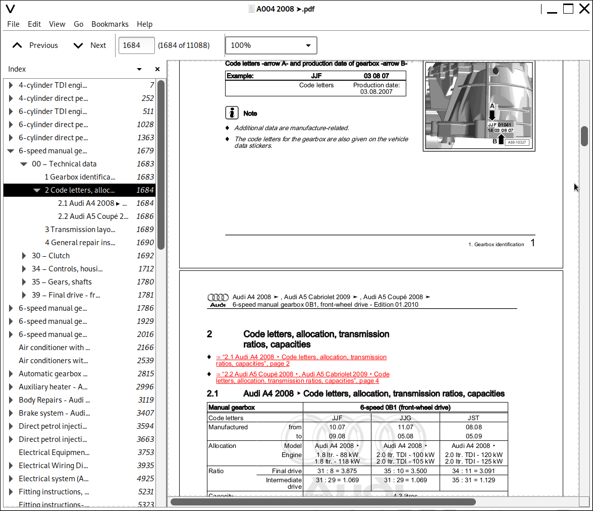
1 Gearbox identification.......1683
2 Code letters, allocation, transmission ratios, capacities.......1684
2.1 Audi A4 2008 > Code letters, allocation, transmission ratios, capacities.......1684
2.2 Audi A5 Coup> 2008 >, Audi A5 Cabriolet 2009 > Code letters, allocation, transmission ratios, capacities.......1686
3 Transmission layout.......1689
4 General repair instructions.......1690
30 > Clutch.......1692
1 Servicing clutch mechanism.......1692
1.1 Exploded view - pedal cluster (LHD vehicles).......1692
1.2 Removing and installing over-centre spring.......1693
1.3 Removing and installing clutch pedal.......1695
2 Exploded view - pedal cluster (RHD vehicles).......1697
3 Exploded view - clutch hydraulics.......1699
3.1 Notes on removing and installing clutch master cylinder and clutch slave cylinder.......1700
3.2 Function check for clutch master cylinder and slave cylinder.......1701
3.3 Removing and installing clutch master cylinder.......1702
3.4 Removing and installing clutch slave cylinder.......1705
3.5 Bleeding clutch system.......1706
4 Exploded view - clutch module.......1709
5 Clutch, clutch release mechanism.......1711
34 > Controls, housing.......1712
1 Overview - selector mechanism.......1712
2 Exploded view - gear knob with gear lever boot.......1713
2.1 Removing and installing gear knob with gear lever boot.......1713
2.2 Removing and installing noise insulation.......1714
3 Exploded view - selector mechanism.......1716
3.1 Removing and installing selector mechanism.......1717
3.2 Adjusting selector mechanism.......1722
4 Removing and installing gearbox.......1725
4.1 Removing gearbox > vehicles with 1.8 ltr. and 2.0 ltr. TFSI engine.......1725
4.2 Installing gearbox > vehicles with 1.8 ltr. and 2.0 ltr. TFSI engine.......1733
4.3 Removing gearbox > vehicles with 4-cylinder diesel engine.......1743
4.4 Installing gearbox > vehicles with 4-cylinder diesel engine.......1753
5 Exploded view - tunnel cross member, gearbox mounting and gearbox support.......1764
5.1 Removing and installing tunnel cross member.......1764
5.2 Removing and installing gearbox support with gearbox mounting.......1766
5.3 Removing and installing gearbox mounting.......1766
6 Checking oil level in manual gearbox.......1767
7 Removing and installing gearbox neutral position sender -G701-.......1768
8 Removing and installing gear detector switch -F208- with gearbox installed.......1770
9 Removing and installing oil seal for selector shaft with gearbox installed.......1774
10 Removing and installing selector shaft with gearbox installed.......1777
11 Dismantling and assembling gearbox.......1779
35 > Gears, shafts.......1780
1 Dismantling and assembling input shaft and output shaft.......1780
39 > Final drive - front differential.......1781
1 Renewing oil seals for flange shafts.......1781
1.1 Renewing oil seal for flange shaft (right-side) with gearbox installed.......1781
2 Front differential.......1785
6-speed manual gearbox 0B2, four-wheel drive - Audi A4 2008 >, Audi A5 Coup> 2008 >.......1786
00 > Technical data.......1790
1 Gearbox identification.......1790
2 Code letters, allocation, transmission ratios, capacities.......1791
2.1 Audi A4 2008 > Code letters, allocation, transmission ratios, capacities.......1791
2.2 Audi A5 Coup> 2008 > Code letters, allocation, transmission ratios, capacities.......1793
2.3 Audi A5 Sportback 2010 > Code letters, allocation, transmission ratios, capacities.......1794
3 Identification of rear final drive units 0BC and 0BD.......1796
3.1 Rear final drive 0BC.......1796
3.2 Rear final drive 0BD.......1797
3.3 Transmission layout.......1799
4 General repair instructions.......1800
30 > Clutch.......1802
1 Servicing clutch mechanism.......1802
1.1 Exploded view - pedal cluster (LHD vehicles).......1802
1.2 Removing and installing over-centre spring.......1803
1.3 Removing and installing clutch pedal.......1806
2 Exploded view - pedal cluster (RHD vehicles).......1807
3 Exploded view - clutch hydraulics.......1809
3.1 Notes on removing and installing clutch master cylinder and clutch slave cylinder.......1810
3.2 Function check for clutch master cylinder and slave cylinder.......1811
3.3 Removing and installing clutch master cylinder.......1812
3.4 Removing and installing clutch slave cylinder.......1815
3.5 Bleeding clutch system.......1817
4 Exploded view - clutch module.......1820
4.1 Tightening sequence - clutch module to drive plate.......1821
5 Clutch, clutch release mechanism.......1823
34 > Controls, housing.......1824
1 Overview - selector mechanism.......1824
2 Exploded view - gear knob with gear lever boot.......1825
2.1 Removing and installing gear knob with gear lever boot.......1825
2.2 Removing and installing noise insulation.......1826
3 Exploded view - selector mechanism.......1828
3.1 Removing and installing selector mechanism.......1829
3.2 Adjusting selector mechanism.......1835
4 Removing and installing gearbox.......1839
4.1 Removing gearbox > vehicles with 4-cylinder diesel engine.......1839
4.2 Installing gearbox > vehicles with 4-cylinder diesel engine.......1850
4.3 Removing gearbox - vehicles with 3.2 ltr. FSI engine.......1861
4.4 Installing gearbox > vehicles with 3.2 ltr. FSI engine.......1869
4.5 Removing gearbox > vehicles with 1.8 ltr. and 2.0 ltr. TFSI engine.......1879
4.6 Installing gearbox > vehicles with 1.8 ltr. and 2.0 ltr. TFSI engine.......1887
5 Exploded view > tunnel cross member, gearbox mounting and gearbox support.......1897
5.1 Removing and installing tunnel cross member.......1897
5.2 Removing and installing gearbox support with gearbox mounting.......1899
5.3 Removing and installing gearbox mounting.......1899
6 Checking oil level in manual gearbox.......1900
7 Removing and installing gearbox neutral position sender -G701-.......1901
8 Removing and installing gear detector switch -F208- with gearbox installed.......1903
9 Removing and installing oil seal for selector shaft with gearbox installed.......1907
10 Removing and installing selector shaft with gearbox installed.......1910
11 Exploded view > centre differential and centre differential housing.......1912
11.1 Removing and installing centre differential with gearbox installed.......1913
11.2 Renewing oil seal for flange shaft.......1919
12 Dismantling and assembling gearbox.......1922
35 > Gears, shafts.......1923
1 Dismantling and assembling input shaft and output shaft.......1923
39 > Final drive - front differential.......1924
1 Renewing oil seals for flange shafts.......1924
1.1 Renewing oil seal for flange shaft (right-side) with gearbox installed.......1924
2 Front differential.......1928
6-speed manual gearbox 0B3, front-wheel drive - Audi A4 2008 >, Audi A5 Cabriolet 2009 >, Audi A5 Coup> 2008 >.......1929
00 > Technical data.......1933
1 Gearbox identification.......1933
1.1 Code letters, allocation, transmission ratios, capacities.......1933
2 Transmission layout.......1935
3 General repair instructions.......1936
30 > Clutch.......1939
1 Servicing clutch mechanism.......1939
1.1 Exploded view - pedal cluster (LHD vehicles).......1939
1.2 Removing and installing over-centre spring.......1940
1.3 Removing and installing clutch pedal.......1942
2 Exploded view - pedal cluster (RHD vehicles).......1944
3 Exploded view - clutch hydraulics.......1946
3.1 Notes on removing and installing clutch master cylinder and slave cylinder.......1947
3.2 Function check for clutch master cylinder and slave cylinder.......1948
3.3 Removing and installing clutch master cylinder.......1949
3.4 Removing and installing clutch slave cylinder.......1953
3.5 Bleeding clutch system.......1955
4 Exploded view - clutch module.......1957
4.1 Tightening sequence - clutch module to drive plate.......1958
5 Clutch, clutch release mechanism.......1960
34 > Controls, housing.......1961
1 Servicing selector mechanism.......1961
1.1 Installation position of selector mechanism.......1961
1.2 Exploded view - gear knob with gear lever boot.......1962
1.3 Removing and installing gear knob with gear lever boot.......1962
1.4 Removing and installing noise insulation.......1963
1.5 Exploded view - selector mechanism.......1965
1.6 Removing and installing selector mechanism.......1966
1.7 Adjusting selector mechanism.......1971
2 Removing and installing gearbox.......1975
2.1 Removing gearbox - vehicles with 2.7 ltr. TDI engine.......1975
2.2 Installing gearbox - vehicles with 2.7 ltr. TDI engine.......1982
3 Transporting gearbox.......1992
4 Exploded view - tunnel cross member, gearbox mounting and gearbox support.......1993
4.1 Removing and installing tunnel cross member.......1993
4.2 Removing and installing gearbox support with gearbox mounting.......1995
4.3 Removing and installing gearbox mounting.......1995
5 Checking oil level in manual gearbox.......1996
6 Removing and installing gear detector switch -F208- with gearbox installed.......1997
7 Removing and installing oil seal for selector shaft with gearbox installed.......2000
8 Dismantling and assembling gearbox.......2003
35 > Gears, shafts.......2004
1 Dismantling and assembling input shaft and output shaft.......2004
39 > Final drive - front differential.......2005
1 Exploded view - oil seals on gearbox.......2005
1.1 Renewing oil seal for flange shaft (right-side).......2006
1.2 Renewing cover for final drive.......2009
6-speed manual gearbox 0B4, four-wheel drive - Audi A4 2008 >, Audi A5 Coup> 2008 >.......2016
00 > Technical data.......2020
1 Gearbox identification.......2020
2 Code letters, allocation, transmission ratios, capacities.......2021
2.1 Audi A4 2008 > Code letters, allocation, transmission ratios, capacities.......2021
2.2 Audi A5 Coup> 2008 > Code letters, allocation, transmission ratios, capacities.......2022
2.3 Audi A5 Sportback 2008 > Code letters, allocation, transmission ratios, capacities.......2023
3 Identification of rear final drive units 0BC, 0BF and 0BE.......2025
3.1 Rear final drive 0BC.......2025
3.2 Rear final drive 0BF and 0BE - sport differential.......2026
4 Transmission layout.......2028
5 General repair instructions.......2029
30 > Clutch.......2032
1 Servicing clutch mechanism.......2032
1.1 Exploded view - pedal cluster (LHD vehicles).......2032
1.2 Removing and installing over-centre spring.......2033
1.3 Removing and installing clutch pedal.......2036
2 Exploded view - pedal cluster (RHD vehicles).......2037
3 Exploded view - clutch hydraulics.......2039
3.1 Notes on removing and installing clutch master cylinder and slave cylinder.......2040
3.2 Function check for master and slave cylinders.......2041
3.3 Removing and installing clutch master cylinder.......2042
3.4 Renewing clutch slave cylinder.......2045
3.5 Bleeding clutch system.......2047
4 Exploded view - clutch module.......2050
4.1 Tightening sequence - clutch module to drive plate (6-cylinder and 8-cylinder engine).......2051
5 Clutch, clutch release mechanism.......2053
34 > Controls, housing.......2054
1 Servicing selector mechanism.......2054
1.1 Installation position of selector mechanism.......2054
1.2 Exploded view - gear knob with gear lever boot.......2055
1.3 Removing and installing gear knob with gear lever boot.......2055
1.4 Removing and installing noise insulation.......2056
1.5 Exploded view - selector mechanism.......2058
1.6 Removing and installing selector mechanism.......2059
1.7 Adjusting selector mechanism.......2064
2 Removing and installing gearbox.......2068
2.1 Removing gearbox - vehicles with 3.0 ltr. TFSI engine.......2068
2.2 Installing gearbox - vehicles with 3.0 ltr. TFSI engine.......2079
2.3 Removing gearbox - vehicles with 4.2 ltr. FSI engine.......2088
2.4 Installing gearbox - vehicles with 4.2 ltr. FSI engine.......2100
2.5 Removing gearbox - vehicles with 3.0 ltr. TDI engine.......2109
2.6 Installing gearbox - vehicles with 3.0 ltr. TDI engine.......2117
3 Transporting gearbox.......2127
4 Exploded view - tunnel cross member, gearbox mounting and gearbox support.......2128
4.1 Removing and installing tunnel cross member.......2128
4.2 Removing and installing gearbox support with gearbox mounting.......2130
4.3 Removing and installing gearbox mounting.......2130
5 Checking oil level in manual gearbox.......2131
6 Removing and installing gear detector switch -F208- with gearbox installed.......2132
7 Removing and installing oil seal for selector shaft with gearbox installed.......2135
8 Exploded view > centre differential and centre differential housing.......2138
8.1 Removing and installing centre differential housing and centre differential with gearbox installed.......2139
8.2 Renewing oil seal for flange shaft (rear) on gearbox.......2144
8.3 Renewing oil seal for rear splined shaft - vehicles without vibration damper on rear splined shaft.......2147
8.4 Renewing oil seal for rear splined shaft - vehicles with vibration damper on rear splined shaft.......2149
9 Dismantling and assembling gearbox.......2153
35 > Gears, shafts.......2154
1 Dismantling and assembling input shaft and output shaft.......2154
39 > Final drive - front differential.......2155
1 Exploded view - oil seals on gearbox.......2155
1.1 Renewing oil seal for flange shaft (right-side).......2156
1.2 Renewing cover for final drive.......2160
Air conditioner with refrigerant R134a - Audi Models.......2166
Air conditioners with refrigerant R1234yf - General information - Audi models.......2539
Automatic gearbox 0B6, four-wheel drive - Audi A4 2008 >, Audi A5 Cabriolet 2009 >, Audi A5 Coup> 2008 >.......2815
00 > Technical data.......2819
1 Gearbox identification.......2819
2 Notes on >6-speed automatic gearbox 0B6>.......2820
3 Transmission layout.......2822
4 Code letters, gearbox allocation, ratios, equipment.......2823
5 Gearbox fluid capacities.......2825
6 Safety precautions.......2826
7 Notes on tow-starting and towing.......2827
8 Repair instructions.......2828
9 Rules for cleanliness when working on the gearbox.......2831
10 Contact corrosion!.......2832
32 > Torque converter.......2833
1 Exploded view - torque converter.......2833
1.1 Identification of torque converter.......2833
1.2 Removing and installing torque converter.......2834
1.3 Draining torque converter.......2836
1.4 Checking torque converter.......2836
1.5 Renewing oil seal for torque converter.......2836
37 > Controls, housing.......2838
1 Electrical/electronic components and fitting locations.......2838
2 Exploded view - selector mechanism.......2841
2.1 Checking selector mechanism.......2842
2.2 Manual release for selector mechanism.......2844
2.3 Removing and installing selector lever lock solenoid -N110-.......2845
2.4 Removing and installing selector lever sensors control unit -J587- and tiptronic switch -F189-.......2847
2.5 Removing and installing gear selector position P switch -F305-.......2848
2.6 Removing and installing shift unit.......2848
3 Exploded view - selector lever handle, selector lever position display -Y26-.......2852
3.1 Removing and installing selector lever handle.......2852
3.2 Detaching selector lever boot from selector lever handle.......2855
3.3 Removing and installing selector lever position display -Y26-.......2856
4 Exploded view - selector lever cable.......2857
4.1 Removing and installing selector lever cable.......2857
4.2 Adjusting selector lever cable.......2862
4.3 Adjusting selector lever cable to basic setting.......2863
5 Removing and installing gearbox.......2868
5.1 Removing gearbox - vehicles with 2.0 ltr. TFSI engine.......2868
5.2 Installing gearbox - vehicles with 2.0 ltr. TFSI engine.......2878
5.3 Removing gearbox - vehicles with 3.2 ltr. FSI engine.......2885
5.4 Installing gearbox - vehicles with 3.2 ltr. FSI engine.......2895
5.5 Removing gearbox - vehicles with 4.2 ltr. FSI engine.......2902
5.6 Installing gearbox - vehicles with 4.2 ltr. FSI engine.......2910
5.7 Removing gearbox - vehicles with 3.0 ltr. TDI engine.......2917
5.8 Installing gearbox - vehicles with 3.0 ltr. TDI engine.......2925
6 Transporting gearbox.......2933
7 Securing gearbox to engine and gearbox support.......2935
8 Exploded view - tunnel cross member, gearbox mounting and gearbox support.......2936
8.1 Removing and installing tunnel cross member.......2936
8.2 Removing and installing gearbox support with gearbox mounting.......2938
8.3 Removing and installing gearbox mounting.......2939
9 ATF in gearbox.......2940
9.1 Checking and correcting ATF level.......2940
9.2 Draining ATF and filling up after repairs.......2944
10 ATF pipes.......2948
10.1 Exploded view - ATF cooler and ATF pipes (vehicles with 4-cyl. or 6-cyl. engine).......2949
10.2 Exploded view - ATF cooler and ATF pipes (vehicles with 8-cyl. engine).......2950
10.3 Cleaning ATF pipes.......2951
38 > Gears, control.......2953
1 Exploded view - ATF oil pan, ATF strainer and mechatronic unit.......2953
1.1 Removing and installing ATF oil pan.......2955
1.2 Removing and installing ATF strainer.......2957
1.3 Removing and installing mechatronic unit.......2958
1.4 Removing and installing wiring harness in gearbox.......2962
39 > Final drive - front differential.......2964
1 Gear oil in gearbox.......2964
1.1 Checking oil level in front final drive and topping up.......2964
1.2 Filling up gear oil in front final drive after repairs.......2965
1.3 Checking gear oil level in transfer box and topping up.......2966
1.4 Filling up gear oil in transfer box after repairs.......2967
2 Exploded view - front final drive.......2970
2.1 Removing and installing flange shaft (left-side).......2971
2.2 Removing and installing flange shaft (right-side).......2973
2.3 Renewing oil seal for flange shaft (left-side).......2975
2.4 Renewing oil seal for flange shaft (right-side).......2978
2.5 Renewing oil seal for selector shaft.......2979
2.6 Renewing O-ring on cover for front final drive.......2981
3 Exploded view - centre differential housing.......2983
3.1 Removing and installing centre differential housing with gearbox installed.......2984
3.2 Renewing oil seal for flange shaft (rear).......2989
3.3 Renewing ball bearing for flange shaft (rear).......2992
3.4 Renewing ball bearing for centre differential.......2994
Auxiliary heater - Audi A4 2008 > Audi A5 Coup> 2008 > Audi A5 Sportback 2010 >.......2996
82 > Auxiliary heating.......3000
1 Repairing auxiliary heater .......3000
1.1 Contact corrosion.......3000
1.2 Notes on auxiliary heater.......3001
1.3 Notes on auxiliary heater operation on vehicles with diesel engine.......3002
1.4 Notes for vehicles with a start/stop system.......3002
2 Rules for cleanliness when working on auxiliary heater (and fuel system).......3003
3 Safety precautions when working on vehicles fitted with auxiliary heater.......3004
3.1 Safety precautions for vehicles with a start/stop system.......3004
4 Notes on general repair work on vehicles fitted with auxiliary heater.......3005
5 Block diagram of components for auxiliary heater in vehicle.......3007
5.1 Auxiliary heater remote control unit buttons and indicator lamp.......3011
5.2 Checking and replacing batteries in auxiliary heater remote control (hand transmitter).......3014
5.3 Adaption of auxiliary heater remote control in supplementary heater control unit -J364-.......3015
5.4 Activating and deactivating auxiliary heating/auxiliary ventilation by way of Multi Media Interface (MMI).......3016
6 Diverting fuel for auxiliary heater.......3018
6.1 Diverting fuel (for auxiliary heater) from fuel tank.......3020
6.1.1 Fuel delivery unit in fuel tank.......3020
6.1.2 Filling fuel pipe to metering pump -V54- with fuel (bleeding).......3021
6.2 Checking fuel delivery rate of metering pump -V54-.......3022
6.2.1 Test requirements.......3022
6.2.2 Preparation.......3023
6.2.3 Complete filling of fuel pipe.......3023
6.2.4 Checking fuel delivery rate.......3026
6.3 Exploded view of metering pump -V54-.......3028
6.4 Removing and installing metering pump -V54-.......3029
6.5 Unfastening quick-release coupling at auxiliary heater fuel pipe.......3031
6.6 Routing of fuel pipe to auxiliary heater.......3032
7 Checking CO2 content in exhaust gas of auxiliary heater.......3033
7.1 Checking CO2 content in exhaust gas of auxiliary heater.......3033
7.1.1 Checking CO2 content.......3033
8 Incorporation of auxiliary heater into coolant circuit.......3038
8.1 Incorporation of auxiliary heater.......3038
8.2 Removing and installing circulation pump -V55-.......3041
8.3 Operation of heater coolant shut-off valve -N279-.......3044
8.4 Removing and installing heater coolant shut-off valve -N279-.......3045
9 Removing and installing auxiliary heater.......3048
9.1 Removing auxiliary heater.......3051
9.2 Installing auxiliary heater.......3054
9.3 Bleeding coolant circuit.......3057
10 Detaching and attaching auxiliary heater add-on components .......3061
10.1 Exploded view of auxiliary heater add-on components.......3061
10.2 Removing and installing intake air noise insulation.......3068
10.3 Removing and installing auxiliary heater exhaust system.......3069
10.4 Removing and installing holder and add-on components of auxiliary heater.......3071
11 Checking electrical components of auxiliary heater.......3073
11.1 Checking actuation and electrical connections of auxiliary heater.......3073
11.2 Preparation for checking auxiliary heater components.......3074
11.3 Checking glow plug for heater -Q9-.......3075
11.4 Checking combustion air blower -V6-.......3075
11.5 Checking flame monitor -G64-.......3076
11.6 Checking temperature sensor -G18-.......3077
11.7 Checking supplementary and auxiliary heater temperature sensor 2 -G587-.......3077
11.8 Checking fuel pre-heating heater element -Z66-.......3078
12 Functional description of auxiliary heater.......3080
12.1 Operating sequence.......3081
12.1.1 Requirements for the sequence described on the following pages.......3081
12.1.2 Activation of auxiliary heating.......3082
12.1.3 Auxiliary heater heating mode.......3086
12.1.4 Deactivation of auxiliary heating.......3089
12.1.5 Auxiliary ventilation.......3090
12.1.6 Measured values and components monitored during operating sequence.......3091
12.2 Sequence with required heat output between 50 and 100 %.......3092
12.3 Sequence with required heat output less than 50 %.......3093
12.4 Actuation of heater coolant shut-off valve -N279-.......3094
13 Dismantling and assembling auxiliary heater.......3096
13.1 Exploded view of auxiliary heater components.......3098
13.2 Dismantling and assembling auxiliary heater.......3101
13.3 Removing and installing temperature sensor -G18-.......3104
13.4 Removing and installing supplementary and auxiliary heater temperature sensor 2 -G587-.......3105
13.5 Removing and installing flame monitor -G64-.......3106
13.6 Removing and installing glow plug for heater -Q9-.......3107
13.7 Removing and installing fuel pre-heating heater element -Z66-.......3108
13.8 Removing and installing combustion air blower -V6-.......3109
13.9 Removing and installing burner element.......3110
13.10 Removing and installing heat exchanger.......3111
14 Block diagram of auxiliary heater.......3113
14.1 Incorporation of auxiliary heater into vehicle electrical system.......3113
15 Block diagram of auxiliary heater actuation with remote control.......3116
15.1 Fitting location for auxiliary heating radio controlled receiver -R64-.......3118
Body Repairs - Audi A4 2008 >.......3119
00 > Technical data.......3125
1 General notes.......3125
2 Vehicle identification data.......3126
2.1 Type plate and vehicle identification number.......3126
2.2 Vehicle data sticker.......3126
3 Ultra-high-strength steels (hot-formed).......3127
4 Expanded foam inserts.......3133
5 Body panel gaps/shut lines.......3136
6 Laser welding.......3140
7 Bonded joints.......3141
7.1 Bonded joints.......3141
7.2 Spot-welded/bonded joints.......3141
7.3 Inspecting and repairing bonded joints.......3141
7.4 Repair methods for replacing body parts.......3141
8 Straightening jig.......3143
9 Body dimensions.......3144
9.1 Body - front (saloon and Avant identical).......3145
9.2 Body - centre (saloon).......3147
9.3 Body - centre (Avant).......3150
9.4 Floor group - front (saloon and Avant identical).......3153
9.5 Floor group - rear (saloon and Avant identical).......3154
9.6 Body - rear (saloon).......3155
9.7 Body - rear (Avant).......3156
50 > Body - front.......3158
1 Intermediate piece - Renewal .......3158
1.1 Tools.......3158
1.2 Procedure.......3159
2 Upper wheel housing longitudinal member - Renewal.......3163
2.1 Tools.......3163
2.2 Procedure.......3164
3 Suspension strut mounting - Renewal .......3167
3.1 Tools.......3167
3.2 Procedure.......3167
4 Front longitudinal member - Partial renewal.......3173
4.1 Tools.......3173
4.2 Procedure.......3173
5 Front longitudinal member - Renewal.......3179
5.1 Tools.......3179
5.2 Procedure.......3180
6 Longitudinal member reinforcement (front) - Renewal.......3189
6.1 Tools.......3189
6.2 Procedure.......3189
51 > Body - centre.......3193
1 Roof - Renewal (saloon).......3193
1.1 Tools.......3193
1.2 Procedure.......3195
1.3 Vehicles with sliding/tilting sunroof.......3208
1.4 Tools.......3209
1.5 Procedure.......3211
2 Roof - Renewal (Avant).......3214
2.1 Tools.......3214
2.2 Procedure.......3215
3 Vehicles with sliding/tilting sunroof (Avant).......3231
3.1 Tools.......3231
3.2 Procedure.......3232
4 Front roof cross member - Renewal.......3250
4.1 Tools.......3250
4.2 Procedure.......3250
5 Roof side member - Renewal.......3254
5.1 Tools.......3255
5.2 Procedure.......3256
5.3 Foam-filling roof side member.......3257
6 Front roof cross member - Renewal (Avant).......3269
6.1 Tools.......3269
6.2 Procedure.......3269
7 Rear roof frame - Renewal.......3274
7.1 Tools.......3274
7.2 Procedure.......3274
8 Rear roof frame - Renewal (Avant).......3278
8.1 Tools.......3278
8.2 Procedure.......3278
9 A-pillar - Renewal.......3283
9.1 Tools.......3283
9.2 Procedure.......3284
10 Inner A-pillar - Renewal .......3290
10.1 Tools.......3290
10.2 Procedure.......3291
11 Outer B-pillar - Renewal.......3296
11.1 Tools.......3296
11.2 Procedure.......3297
12 Inner B-pillar - Renewal.......3302
12.1 Tools.......3302
12.2 Procedure.......3303
13 Inner B-pillar - Partial renewal.......3309
13.1 Tools.......3309
13.2 Procedure.......3310
14 Outer side member - Renewal.......3314
14.1 Tools.......3314
14.2 Procedure.......3315
15 Inner side member - Renewal.......3318
15.1 Tools.......3318
15.2 Procedure.......3318
16 Inner side member - Partial renewal.......3324
16.1 Tools.......3324
16.2 Procedure.......3324
17 Inner side member reinforcement - Renewal.......3329
17.1 Tools.......3329
17.2 Procedure.......3329
53 > Body - rear.......3336
1 Rear cross panel (top section) - Renewal.......3336
1.1 Tools.......3336
1.2 Procedure.......3336
2 Rear cross panel (top section) - Renewal (Avant).......3339
2.1 Tools.......3339
2.2 Procedure.......3339
3 Rear cross panel - Renewal.......3343
3.1 Tools.......3343
3.2 Procedure.......3344
4 Rear cross panel - Renewal (Avant).......3347
4.1 Tools.......3347
4.2 Procedure.......3347
5 Cross panel (inner section) - Renewal.......3351
5.1 Tools.......3351
5.2 Procedure.......3351
6 Cross panel (inner section) - Renewal (Avant).......3354
6.1 Tools.......3354
6.2 Procedure.......3354
7 Tail light mounting - Renewal.......3358
7.1 Tools.......3358
7.2 Procedure.......3358
8 Rear longitudinal member - Partial renewal.......3361
8.1 Tools.......3361
8.2 Procedure.......3362
9 Rear longitudinal member - Renewal .......3367
9.1 Tools.......3367
9.2 Procedure.......3367
10 Side panel - Renewal.......3374
10.1 Tools.......3374
10.2 Procedure.......3375
11 Side panel - Renewal (Avant).......3383
11.1 Tools.......3383
11.2 Procedure.......3384
12 C-pillar reinforcement - Renewal.......3395
12.1 Tools.......3395
12.2 Procedure.......3395
13 Rear wheel housing - Renewal.......3398
13.1 Tools.......3398
13.2 Procedure.......3399
14 Spare wheel well - Renewal.......3403
14.1 Tools.......3403
14.2 Procedure.......3403
Brake system - Audi A4 2008 >.......3407
00 > Technical data.......3411
1 Brakes.......3411
2 Brake test.......3413
2.1 General notes.......3413
2.2 Vehicles with front-wheel drive.......3413
2.3 Vehicles with four-wheel drive.......3413
2.4 EPB (Electronic parking brake and handbrake) on brake dynamometer.......3414
3 Brake fluid.......3415
3.1 General notes.......3415
45 > Anti-lock brake system.......3416
1 General information on the anti-lock brake system.......3416
2 Connecting -VAS>5051B/ 5052- and selecting functions.......3417
3 ABS/ESP Bosch 8.1 - overview.......3418
4 Audi hold assist (AHA).......3422
4.1 Removing and installing switch for Audi hold assist (AHA).......3423
5 Removing and installing parts of ABS/ESP system.......3424
5.1 Removing and installing brake light sensor.......3424
5.2 Removing and installing ESP sensor unit -G419-.......3428
5.3 Removing and installing steering angle sender -G85-.......3429
5.4 Removing and installing switch for electronic parking brake.......3430
6 Hydraulic unit -N55- with ABS control unit -J104- - overview.......3431
6.1 Removing and installing hydraulic unit -N55- with ABS control unit -J104-.......3431
6.2 Removing and installing ESP bracket.......3436
7 Speed sensors of ABS/ESP system - overview.......3437
7.1 Removing and installing front speed sensors -G45- / -G47-.......3437
7.2 Removing and installing rear speed sensors -G44- / -G46-.......3438
46 > Brakes - mechanism.......3440
1 Front brakes FN3-57 - exploded view.......3440
1.1 Removing and installing front brake caliper with brake carrier - FN-3 brakes.......3441
1.2 Renewing front brake caliper - FN-3 brakes.......3443
1.3 Removing and installing front brake pads - FN-3 brakes.......3447
1.4 Removing and installing front brake disc - FN-3 brakes.......3450
1.5 Renewing front brake disc - FN-3 brakes.......3451
1.6 Removing and installing front splash plate - FN-3 brakes.......3454
2 Front brakes FBC-57 - exploded view.......3456
2.1 Removing and installing front brake caliper with brake carrier - FBC-57 brakes.......3457
2.2 Renewing front brake caliper - FBC-57 brakes.......3459
2.3 Removing and installing front brake pads - FBC-57 brakes.......3462
2.4 Removing and installing front brake disc - FBC-57 brakes.......3470
2.5 Renewing front brake disc - FBC-57 brakes.......3471
2.6 Removing and installing front splash plate - FBC-57 brakes.......3475
3 Rear brakes with electronic parking brake - exploded view.......3476
3.1 Removing and installing rear brake caliper with brake carrier.......3477
3.2 Renewing rear brake caliper.......3483
3.3 Removing and installing rear brake pads.......3488
3.4 Detaching and attaching rear brake disc.......3493
3.5 Renewing rear brake disc.......3494
3.6 Removing and installing rear splash plate.......3497
4 Brake pedal and mounting bracket - exploded view.......3498
4.1 Separating and connecting brake pedal and brake servo.......3499
4.2 Removing and installing brake pedal (vehicles with manual gearbox).......3502
4.3 Removing and installing brake pedal (vehicles with automatic gearbox).......3505
4.4 Removing and installing mounting for brake servo push rod.......3510
4.5 Removing and installing mounting bracket (vehicles with manual gearbox).......3514
4.6 Removing and installing mounting bracket (vehicles with automatic gearbox).......3526
5 Electronic parking brake (EPB) - overview.......3535
5.1 Removing and installing control unit for electromechanical parking brake -J540-.......3536
5.2 Removing and installing actuator motor for electronic parking brake and handbrake.......3537
47 > Brakes - hydraulics.......3542
1 Leak test.......3542
1.1 Leak test performed by operating brake.......3542
1.2 High-pressure and low-pressure tests.......3542
2 Servicing brake caliper - FN3 brakes.......3544
2.1 Removing and installing piston for front brake caliper - FN-3 brakes.......3545
2.2 Renewing bearing bushes and guide pins - FN-3 brakes.......3546
3 Servicing brake caliper - FBC brakes.......3548
3.1 Removing and installing piston for front brake caliper- FBC brakes.......3549
3.2 Renewing protective caps and guide pins - FBC brakes.......3550
4 Servicing rear caliper for electronic parking brake (EPB).......3555
4.1 Removing and installing piston for rear brake caliper.......3556
4.2 Renewing protective caps and guide pins of rear brakes.......3559
5 Bleeding brake system.......3561
5.1 Procedure for bleeding brake system.......3561
5.2 Changing brake fluid.......3563
6 Brake servo/ brake master cylinder - exploded view.......3564
6.1 Removing and installing cover for brake fluid reservoir.......3565
6.2 Removing and installing brake fluid reservoir.......3567
6.3 Removing and installing brake master cylinder.......3570
6.4 Removing and installing brake servo.......3572
7 Exhauster pumps.......3577
7.1 Exhauster pump - exploded view.......3577
7.2 Removing and installing exhauster pump (2.7 ltr. TDI and 3.0 ltr. TDI diesel engine).......3578
7.3 Removing and installing exhauster pump (2.0 ltr. TDI diesel engine).......3580
7.4 Removing and installing exhauster pump (4-cyl. turbo FSI engine).......3582
7.5 Removing and installing exhauster pump (V6 FSI).......3584
8 Vacuum pump -V192- - overview.......3585
8.1 Removing and installing vacuum pump -V192-.......3585
8.2 Removing and installing bracket for vacuum pump -V192-.......3586
8.3 Checking vacuum pump -V192-.......3587
8.4 Removing and installing brake servo pressure sensor -G294-.......3590
8.5 Removing and installing non-return valve.......3591
8.6 Checking non-return valve.......3591
9 Brake hoses and brake lines.......3592
9.1 Routing of brake hoses/lines.......3592
Direct petrol injection and ignition system (4- cylinder 1.8 ltr.4-valve turbo with timing chain) - Audi A4 2008 >, Audi A5 Cabriolet 2009 >, Audi A5 Coup> 2008 >.......3594
24 > Mixture preparation - injection.......3598
1 Safety precautions and rules for cleanliness.......3598
1.1 General notes on self-diagnosis.......3598
1.2 Safety precautions.......3598
1.3 Rules for cleanliness and instructions for working on fuel system.......3600
1.4 Safety precautions for vehicles with start/stop system.......3600
1.5 Important: Required procedure prior to opening high-pressure injection system.......3600
1.6 Checking vacuum system.......3601
2 Injection system.......3603
2.1 Technical data.......3603
2.2 Overview of fitting locations.......3603
3 Air cleaner.......3613
3.1 Air cleaner - exploded view.......3613
3.2 Removing and installing engine cover panel.......3614
3.3 Removing and installing air filter element.......3614
3.4 Removing air cleaner housing.......3616
4 Intake manifold.......3619
4.1 Intake manifold - exploded view.......3619
4.2 Fuel rail - exploded view.......3621
4.3 Removing and installing intake manifold with fuel rail.......3622
4.4 Removing and installing fuel rail.......3626
5 High-pressure pump.......3628
5.1 High-pressure pump - exploded view.......3628
5.2 Removing and installing high-pressure pump.......3629
6 Injectors.......3632
6.1 Removing and installing injectors.......3632
6.1.1 Renewing combustion chamber ring seal (teflon ring seal).......3633
6.2 Cleaning injectors.......3635
7 Components of injection system.......3637
7.1 Removing and installing fuel pressure sender -G247-.......3637
7.2 Checking fuel pressure sender -G247-.......3638
7.3 Checking residual pressure in fuel system (up to high-pressure pump).......3640
7.4 Removing and installing air mass meter -G70-.......3643
7.5 Removing and installing throttle valve module -J338-.......3643
7.6 Cleaning throttle valve module -J338-.......3644
7.7 Checking intake manifold change-over function.......3645
7.8 Checking dual non-return valve.......3646
8 Lambda probes.......3649
8.1 Lambda probes - overview.......3649
8.2 Removing and installing Lambda probe -G39- and Lambda probe heater -Z19- before catalytic converter.......3649
8.3 Removing and installing Lambda probe after catalytic converter -G130- and Lambda probe 1 heater after catalytic converter -Z29-.......3650
9 Engine control unit.......3652
9.1 Wiring and component check with test box -V.A.G 1598/42-.......3652
9.2 Renewing engine control unit -J623-.......3654
28 > Ignition system.......3658
1 General notes and safety precautions.......3658
1.1 General notes on ignition system.......3658
1.2 Safety precautions.......3658
2 Servicing ignition system.......3659
2.1 Test data.......3659
2.2 Ignition system - exploded view.......3659
2.3 Removing and installing ignition coils with output stages.......3660
2.4 Removing knock sensor 1 -G61-.......3661
2.5 Removing and installing engine speed sender -G28-.......3661
Direct petrol injection and ignition system (4- cylinder 2.0 ltr. 4-valve turbo with timing chain) - Audi A4 2008 >, Audi A5 Cabriolet 2009 >, Audi A5 Coup> 2008 >.......3663
24 > Mixture preparation - injection.......3667
1 Safety precautions and rules for cleanliness.......3667
1.1 General notes on self-diagnosis.......3667
1.2 Safety precautions.......3667
1.3 Safety precautions for vehicles with start/stop system.......3669
1.4 Rules for cleanliness and instructions for working on fuel system.......3669
1.5 Important: Required procedure prior to opening high-pressure injection system.......3669
1.6 Checking vacuum system.......3670
2 Injection system.......3672
2.1 Technical data.......3672
2.2 Overview of fitting locations (vehicles with engine codes CDNB, CDNC, CAEB, CDZA, CAEA and CADA).......3672
2.3 Overview of fitting locations (vehicles with engine code CFKA).......3682
3 Air cleaner.......3692
3.1 Air cleaner - exploded view.......3692
3.2 Removing and installing engine cover panel.......3693
3.3 Removing and installing air filter element.......3693
3.4 Removing air cleaner housing.......3695
4 Intake manifold (vehicles with engine codes CDNB, CDNC, CAEB, CDZA, CAEA and CADA).......3697
4.1 Intake manifold - exploded view.......3697
4.2 Fuel rail - exploded view.......3699
4.3 Removing and installing intake manifold.......3700
4.4 Removing and installing fuel rail.......3704
5 Intake manifold (vehicles with engine code CFKA).......3706
5.1 Intake manifold - exploded view.......3706
5.2 Fuel rail - exploded view.......3708
5.3 Removing and installing intake manifold.......3709
5.4 Removing and installing intake manifold (bottom section).......3713
5.5 Removing and installing fuel rail.......3715
5.6 Removing and installing cold-start valve -N17-.......3715
6 High-pressure pump.......3717
6.1 High-pressure pump - exploded view.......3717
6.2 Removing and installing high-pressure pump.......3718
7 Injectors.......3721
7.1 Removing and installing injectors.......3721
7.1.1 Renewing combustion chamber ring seal (teflon ring seal).......3722
7.2 Cleaning injectors.......3724
8 Components of injection system.......3726
8.1 Removing and installing fuel pressure sender -G247-.......3726
8.2 Checking fuel pressure sender -G247-.......3727
8.3 Checking residual pressure in fuel system (up to high-pressure pump).......3729
8.4 Removing and installing air mass meter -G70-.......3732
8.5 Removing and installing throttle valve module -J338-.......3732
8.6 Cleaning throttle valve module -J338-.......3733
8.7 Checking intake manifold change-over function.......3734
8.8 Checking dual non-return valve.......3735
9 Lambda probes.......3738
9.1 Lambda probes - overview.......3738
9.2 Removing and installing Lambda probe -G39- and Lambda probe heater -Z19- before catalytic converter.......3739
9.3 Removing and installing Lambda probe after catalytic converter -G130- and Lambda probe 1 heater after catalytic converter -Z29-.......3740
10 Engine control unit.......3742
10.1 Wiring and component check with test box -V.A.G 1598/42-.......3742
10.2 Renewing engine control unit -J623-.......3744
28 > Ignition system.......3748
1 General notes and safety precautions.......3748
1.1 General notes on ignition system.......3748
1.2 Safety precautions.......3748
2 Servicing ignition system.......3749
2.1 Test data.......3749
2.2 Ignition system - exploded view.......3749
2.3 Removing and installing ignition coils with output stages.......3750
2.4 Removing knock sensor 1 -G61-.......3751
2.5 Removing and installing engine speed sender -G28-.......3751
Electrical Equipment General Information - Audi Models.......3753
Electrical Wiring Diagrams.......3935
001 - .......3935
1. .......3935
2. Entry and start authorisation switch, Fuse 6 on fuse holder D.......3936
3. Control unit in dash panel insert, Radio controlled clock receiver.......3937
4. Fuel gauge sender, Fuel system pressurisation pump, Control unit in dash panel insert.......3938
5. Steering column electronics control unit.......3939
6. Turn signal switch, Cruise control system switch, Steering column electronics control unit.......3940
7. Intermittent wiper switch, Start/Stop operation button, Steering column electronics control unit, Electronic steering column lock control unit.......3941
8. Bonnet contact switch, Treble horn, Bass horn, Horn relay.......3942
9. Rain and light sensor, Wiper motor control unit.......3943
10. Gear detector switch, Front left brake pad wear sender, Headlight washer system pump, Left washer jet heater element, Right washer jet heater element.......3944
11. Brake fluid level warning contact, Ambient temperature sensor, Coolant shortage indicator sender, Windscreen washer fluid level sender, Rear window wiper motor.......3945
12. Switch module for Charisma.......3946
13. Light switch, Hazard warning lights button.......3947
14. Front left headlight.......3948
15. Front right headlight.......3949
16. Rear left reading light button, Vanity mirror light bulb, Front interior light, Rear right interior light.......3950
17. Key operated switch to deactivate front passenger side airbag, Valet parking button, Valet parking warning lamp.......3951
18. Glove compartment light switch, Front left footwell illumination bulb, Front right footwell illumination bulb, Glove compartment light.......3952
19. 12 V socket.......3953
20. Adaptive cruise control unit.......3954
21. Rear roller blind switch, TCS and ESP button, Parking aid button.......3955
22. Entry and start authorisation button.......3956
23. Entry and start authorisation button, Contact sensor for front left exterior door handle, Contact sensor for front right exterior door handle, Convenience system central control unit, Left aerial for entry and start authorisation.......3957
24. Convenience system central control unit, Left tail light, Left tail light 2, Luggage compartment light.......3958
25. Convenience system central control unit, Rear lid central locking motor.......3959
26. Convenience system central control unit, Right tail light, Right tail light 2.......3960
27. Sliding sunroof adjustment regulator, Sliding sunroof adjustment control unit, Convenience system central control unit, Sliding sunroof motor.......3961
28. Anti-theft alarm sensor, Alarm horn, Convenience system central control unit, Central locking and anti-theft alarm system aerial, Aerial amplifier 3.......3962
29. Clutch pedal switch, Convenience system central control unit.......3963
30. Brake light switch, Convenience system central control unit.......3964
31. Convenience system central control unit.......3965
32. Convenience system central control unit.......3966
33. Convenience system central control unit, Rear roller blind motor, Tank filler flap locking motor, Heated rear window.......3967
34. Cigarette lighter, 12 V socket 2, 12 V socket 3.......3968
002 - .......3969
1. .......3969
2. Entry and start authorisation button, Convenience system central control unit, Luggage compartment aerial for entry and start authorisation, Interior aerial 1 for entry and start authorisation.......3970
3. Anti-theft alarm sensor, Alarm horn, Convenience system central control unit, Aerial amplifier 3.......3971
4. Contact sensor for front left exterior door handle, Contact sensor for front right exterior door handle, Convenience system central control unit, Left aerial for entry and start authorisation.......3972
5. Contact sensor for rear left door exterior handle, Contact sensor for rear right exterior door handle, Convenience system central control unit.......3973
6. Window aerial suppression filter, Heated rear window relay, Convenience system central control unit, Heated rear window single fuse, Heated rear window.......3974
7. Rear lid contact switch for anti-theft alarm, Release button for rear lid lock cylinder, Convenience system central control unit, Rear lid central locking motor, Left number plate light, Right number plate light.......3975
8. Driver door control unit.......3976
9. Operating unit for window regulator in driver door, Driver door control unit, Driver side window regulator motor.......3977
10. Driver side central locking lock unit, Driver door control unit.......3978
11. Driver side central locking lock unit, Driver door control unit.......3979
12. Driver seat memory operating unit, Driver side interior locking switch, Rear lid remote release switch, Driver door control unit, Driver door opener illumination bulb, Driver side door warning lamp, Front left entry light.......3980
13. Mirror adjustment switch, Mirror adjustment changeover switch, Adjustment switch for mirror with fold-in feature, Interior monitoring switch, Alarm system off switch, Driver door control unit, Central locking deadlock function warning lamp -SAFE-.......3981
14. Potentiometer for horizontal adjustment of driver side mirror, Potentiometer for vertical adjustment of driver side mirror, Driver door control unit, Driver side mirror adjustment motor, Driver side fold-in mirror motor, Driver side mirror adjustment motor.......3982
15. Driver door control unit, Lane change assist warning lamp in driver side exterior mirror, Driver side turn signal repeater bulb, Driver side entry light in exterior mirror, Driver side automatic anti-dazzle exterior mirror, Heated exterior mirror on d.......3983
16. Front passenger door control unit.......3984
17. Front passenger side central locking lock unit, Front passenger door control unit.......3985
18. Window regulator switch in front passenger door, Front passenger side interior locking switch, Front passenger door control unit.......3986
19. Front passenger door control unit, Front passenger door opener illumination bulb, Front passenger side window regulator motor, Front right entry light, Front passenger side door warning lamp.......3987
20. Potentiometer for horizontal adjustment of front passenger side mirror, Potentiometer for vertical adjustment of front passenger side mirror, Front passenger door control unit, Front passenger side mirror adjustment motor, Front passenger side fold-in mirror motor, Front passenger side mirror adjustment motor.......3988
21. Front passenger door control unit, Lane change assist warning lamp in front passenger side exterior mirror, Front passenger side turn signal repeater bulb, Front passenger side entry light in exterior mirror, Front passenger side automatic anti-dazzle exterior mirror, Heated exterior mirror on front passenger side.......3989
22. Rear left door control unit.......3990
23. Rear left central locking lock unit, Rear left door control unit.......3991
24. Rear left window regulator switch, in door, Rear left interior locking switch, Rear left door control unit.......3992
25. Rear left door control unit, Rear left door opener illumination bulb, Rear left window regulator motor, Rear left entry light, Rear left door warning lamp.......3993
26. Rear right door control unit.......3994
27. Rear right central locking lock unit, Rear right door control unit.......3995
28. Rear right window regulator switch, in door, Rear right interior locking switch, Rear right door control unit.......3996
29. Rear right door control unit, Rear right door opener illumination bulb, Rear right window regulator motor, Rear right entry light, Rear right door warning lamp.......3997
003 - .......3998
1. .......3998
2. Battery, Heated rear window relay, Terminal 15 voltage supply relay, Battery monitor control unit, Convenience system central control unit, Fuse 1 in fuse holder A.......3999
3. Fuse 2 in fuse holder A, Fuse 3 in fuse holder A.......4000
4. Battery isolation igniter, Terminal 30 wiring junction 2, Jump start socket.......4001
5. Starter, Alternator, Terminal 30 wiring junction 2, Jump start socket.......4002
6. Starter motor relay, Starter motor relay 2.......4003
7. Fuse holder B, Fuse carrier 1.......4004
8. Fuse holder B, Fuse carrier 1.......4005
9. Fuse holder C, Fuse carrier 1.......4006
10. Fuse holder C, Fuse carrier 1.......4007
11. Fuse holder C, Fuse carrier 1.......4008
12. Fuse holder C, Fuse carrier 2.......4009
13. Fuse holder C, Fuse carrier 2.......4010
14. Fuse holder C, Fuse carrier 2.......4011
15. Fuse holder C, Fuse carrier 3.......4012
16. Fuse holder C, Fuse carrier 3.......4013
17. Fuse holder D, Fuse carrier 1.......4014
18. Fuse holder D, Fuse carrier 1.......4015
19. Fuse holder D, Fuse carrier 2.......4016
20. Fuse holder D, Fuse carrier 2.......4017
21. Fuse holder D, Fuse carrier 2.......4018
22. Fuse holder F, Fuse carrier 1.......4019
23. Fuse holder F, Fuse carrier 2.......4020
24. Fuse holder F, Fuse carrier 2.......4021
25. Fuse carrier 3.......4022
26. Fuse holder F, Fuse carrier 3.......4023
27. Fuse holder F, Fuse carrier 3.......4024
28. Fuse holder F, Fuse carrier 3.......4025
29. Fuse holder F, Fuse carrier 4.......4026
30. Fuse holder F, Fuse carrier 4.......4027
31. Fuse holder F, Fuse carrier 4.......4028
32. Fuse carrier 5.......4029
004 - .......4030
1. .......4030
2. ABS control unit, Active steering control unit.......4031
3. Digital sound package control unit, Telephone transmitter and receiver unit.......4032
4. Driver door control unit, Onboard supply control unit.......4033
5. .......4034
6. Control unit in dash panel insert, Steering column electronics control unit, Data bus diagnostic interface.......4035
7. Data bus diagnostic interface, Radio, Connection for external audio sources.......4036
8. Climatronic control unit, Front passenger door control unit, Steering column electronics control unit, Data bus diagnostic interface.......4037
9. .......4038
005 - .......4039
1. .......4039
2. Automatic gearbox control unit, Convenience system central control unit, Engine control unit.......4040
3. Automatic gearbox control unit, Data bus diagnostic interface, Engine control unit.......4041
4. Automatic gearbox control unit, Onboard supply control unit, Selector lever sensors control unit.......4042
5. Gear selector position P switch, Automatic gearbox control unit, Selector lever lock solenoid.......4043
006 - .......4044
1. .......4044
2. Automatic gearbox control unit, Convenience system central control unit, Engine control unit.......4045
3. Automatic gearbox control unit, Data bus diagnostic interface, Engine control unit.......4046
4. Automatic gearbox control unit, Onboard supply control unit, Selector lever sensors control unit.......4047
5. Gear selector position P switch, Automatic gearbox control unit, Selector lever lock solenoid.......4048
007 - .......4049
1. .......4049
2. Telephone transmitter and receiver unit, Telephone microphone, Aerial for Bluetooth, Microphone unit in front roof module.......4050
3. Telephone transmitter and receiver unit, Radio, telephone and navigation system aerial, Telephone bracket.......4051
008 - .......4052
1. .......4052
2. Battery, Terminal 15 voltage supply relay.......4053
3. Suppression filter, Battery isolation igniter, Jump start socket.......4054
4. Starter, Alternator, Terminal 30 wiring junction 2, Jump start socket.......4055
5. Fuel pump relay, Terminal 30 voltage supply relay, Engine control unit.......4056
6. Starter motor relay, Engine control unit, Starter motor relay 2.......4057
7. Automatic glow period control unit, Engine control unit.......4058
8. Oil level and oil temperature sender, Engine control unit.......4059
9. Throttle valve module, Engine control unit, Left electrohydraulic engine mounting solenoid valve, Right electrohydraulic engine mounting solenoid valve.......4060
10. Engine control unit, Auxiliary air heater element.......4061
11. Accelerator position sender, Accelerator position sender 2, Engine control unit.......4062
12. Engine speed sender, Hall sender, Fuel pressure sender, Engine control unit.......4063
13. Charge pressure sender, Intake air temperature sender, Engine control unit.......4064
14. Exhaust gas pressure sensor 1, Engine control unit, Turbocharger 1 control unit.......4065
15. Air mass meter, Engine control unit.......4066
16. Coolant temperature sender, Engine control unit.......4067
17. Lambda probe, Engine control unit.......4068
18. Engine control unit, Injector, cylinder 1, Injector, cylinder 6.......4069
19. Clutch position sender, Engine control unit.......4070
20. Brake light switch, Engine control unit, Supplementary fuel pump.......4071
21. Data bus diagnostic interface, Engine control unit.......4072
22. Control unit in dash panel insert, Data bus diagnostic interface.......4073
23. Fuel gauge sender, Fuel system pressurisation pump, Control unit in dash panel insert.......4074
24. Oil pressure switch, Coolant shortage indicator sender, Onboard supply control unit.......4075
009 - .......4076
1. .......4076
2. Active steering control unit, Electromechanical power steering motor.......4077
3. Lateral acceleration sender, Yaw rate sender, Longitudinal acceleration sender, ESP sensor unit, ESP sensor unit 2, ABS control unit, Active steering control unit.......4078
4. Control unit in dash panel insert, Active steering control unit, Steering hydraulics pump.......4079
010 - .......4080
1. .......4080
2. Battery, Terminal 15 voltage supply relay.......4081
3. Battery isolation igniter, Terminal 30 wiring junction 2, Jump start socket.......4082
4. Starter, Alternator, Voltage regulator, Jump start socket.......4083
5. Main relay, Engine control unit, Engine component current supply relay.......4084
6. Starter motor relay, Engine control unit, Starter motor relay 2, Fuse carrier 1.......4085
7. Oil level and oil temperature sender, Engine control unit, Fuse carrier 1.......4086
8. Engine control unit, Camshaft control valve 1, Exhaust camshaft control valve 1, Climatronic coolant shut-off valve, Continued coolant circulation pump.......4087
9. Actuator 1 for camshaft adjustment, Engine control unit, Left electrohydraulic engine mounting solenoid valve, Exhaust camshaft control valve 2.......4088
10. Actuator 6 for camshaft adjustment, Actuator 7 for camshaft adjustment, Actuator 8 for camshaft adjustment, Engine control unit.......4089
11. Engine control unit, Activated charcoal filter solenoid valve 1, Variable intake manifold changeover valve, Fuel metering valve, Fuel system diagnostic pump.......4090
12. Engine control unit, Secondary air inlet valve, Valve for oil pressure control, Secondary air pump motor.......4091
13. Engine control unit, Ignition coil 1 with output stage, Ignition coil 2 with output stage, Ignition coil 3 with output stage.......4092
14. Engine control unit, Ignition coil 4 with output stage, Ignition coil 5 with output stage, Ignition coil 6 with output stage.......4093
15. Knock sensor 1, Knock sensor 2, Engine control unit.......4094
16. Engine speed sender, Coolant temperature sender, Fuel pressure sender for low-pressure, Throttle valve module, Engine control unit.......4095
17. Hall sender, Intake air temperature sender, Fuel pressure sender, Engine control unit.......4096
18. Accelerator position sender, Hall sender 2, Accelerator position sender 2, Hall sender 3, Sender 1 for secondary air pressure, Engine control unit.......4097
19. Oil pressure switch for reduced oil pressure, Hall sender 4, Variable intake manifold position sender, Engine control unit.......4098
20. Engine control unit, Injector, cylinder 1, Injector, cylinder 2, Injector, cylinder 3, Injector, cylinder 4, Injector, cylinder 5, Injector, cylinder 6.......4099
21. Lambda probe, Lambda probe 2, Engine control unit.......4100
22. Lambda probe after catalytic converter, Lambda probe 2 after catalytic converter, Engine control unit.......4101
23. Clutch position sender, Engine control unit.......4102
24. Brake light switch, Engine control unit.......4103
25. Automatic gearbox control unit, Data bus diagnostic interface, Engine control unit.......4104
26. Control unit in dash panel insert, Data bus diagnostic interface.......4105
27. Fuel gauge sender, Fuel system pressurisation pump, Control unit in dash panel insert, Fuel pump control unit.......4106
28. Oil pressure switch, Coolant shortage indicator sender, Onboard supply control unit.......4107
29. Circulation pump relay, Coolant circulation pump.......4108
011 - .......4109
1. .......4109
2. Data bus diagnostic interface.......4110
3. Airbag control unit, Data bus diagnostic interface.......4111
012 - .......4112
1. .......4112
2. Battery, Terminal 15 voltage supply relay, Battery monitor control unit.......4113
3. Battery isolation igniter, Jump start socket.......4114
4. Starter, Alternator, Voltage regulator, Suppression filter, Terminal 30 wiring junction 2, Jump start socket.......4115
5. Main relay, Engine control unit, Engine component current supply relay.......4116
6. Starter motor relay, Engine control unit, Starter motor relay 2.......4117
7. Oil level and oil temperature sender, Engine control unit.......4118
8. Engine control unit, Charge pressure control solenoid valve, Activated charcoal filter solenoid valve 1, Left electrohydraulic engine mounting solenoid valve, Camshaft control valve 1, Turbocharger air recirculation valve, Intake manifold flap valve, Valve for oil pressure control.......4119
9. Additional coolant pump relay, Engine control unit, Climatronic coolant shut-off valve, Continued coolant circulation pump.......4120
10. Engine control unit, Ignition coil 1 with output stage, Ignition coil 2 with output stage, Ignition coil 3 with output stage, Ignition coil 4 with output stage.......4121
11. Accelerator position sender, Accelerator position sender 2, Engine control unit.......4122
12. Engine speed sender, Hall sender, Knock sensor 1, Engine control unit.......4123
13. Charge pressure sender, Fuel pressure sender, Intake manifold flap potentiometer, Throttle valve module, Engine control unit.......4124
14. Oil pressure switch, Oil pressure switch for reduced oil pressure, Intake air temperature sender, Coolant temperature sender, Engine control unit.......4125
15. Air mass meter, Engine control unit, Fuel pressure regulating valve.......4126
16. Engine control unit, Injector, cylinder 1, Injector, cylinder 2, Injector, cylinder 3, Injector, cylinder 4.......4127
17. Lambda probe, Lambda probe after catalytic converter, Engine control unit.......4128
18. Clutch position sender, Engine control unit.......4129
19. Brake light switch, Steering column electronics control unit, Engine control unit.......4130
20. Automatic gearbox control unit, Data bus diagnostic interface, Engine control unit.......4131
21. Control unit in dash panel insert, Data bus diagnostic interface.......4132
22. Fuel gauge sender, Fuel system pressurisation pump, Control unit in dash panel insert, Fuel pump control unit.......4133
23. Gear detector switch, Coolant shortage indicator sender, Onboard supply control unit, Servotronic solenoid valve, Air conditioner compressor regulating valve.......4134
013 - .......4135
1. .......4135
2. Light switch, Rear left vehicle level sender, Headlight range control unit, Onboard supply control unit.......4136
3. Left gas discharge bulb control unit, Headlight range control unit, Onboard supply control unit, Left headlight range control motor, Left dip beam screen motor.......4137
4. Headlight range control unit, Onboard supply control unit, Left LED module for daytime running light and side light.......4138
5. Right gas discharge bulb control unit, Headlight range control unit, Onboard supply control unit, Right gas discharge (xenon) bulb, Right headlight range control motor, Right dip beam screen motor.......4139
6. Onboard supply control unit, Right parking light bulb.......4140
014 - .......4141
1. .......4141
2. Battery, Battery monitor control unit, Battery isolation igniter, Fuse 2 in fuse holder A, Terminal 30 wiring junction 2.......4142
3. Main relay, Radiator fan control unit, Terminal 30 wiring junction 2, Radiator fan.......4143
015 - .......4144
1. .......4144
2. Battery, Battery monitor control unit, Battery isolation igniter, Fuse 2 in fuse holder A.......4145
3. Main relay, Radiator fan control unit, Fuse 11 on fuse holder B, Radiator fan.......4146
016 - .......4147
1. .......4147
2. Battery, Battery monitor control unit, Battery isolation igniter, Fuse 2 in fuse holder A.......4148
3. Radiator fan control unit, Terminal 30 voltage supply relay, Fuse 11 on fuse holder B, Fuse 1 (30), Radiator fan.......4149
017 - .......4150
1. .......4150
2. Battery, Battery monitor control unit, Battery isolation igniter, Fuse 2 in fuse holder A.......4151
3. Radiator fan control unit, Terminal 30 voltage supply relay, Fuse 11 on fuse holder B, Fuse 1 (30), Radiator fan.......4152
018 - .......4153
1. .......4153
2. Battery, Battery monitor control unit, Battery isolation igniter, Fuse 2 in fuse holder A, Terminal 30 wiring junction 2.......4154
3. Main relay, Radiator fan control unit, Radiator fan control unit 2, Terminal 30 wiring junction 2, Radiator fan, Radiator fan 2.......4155
019 - .......4156
1. .......4156
2. Battery, Battery monitor control unit, Battery isolation igniter, Fuse 2 in fuse holder A, Terminal 30 wiring junction 2.......4157
3. Main relay, Radiator fan control unit, Radiator fan control unit 2, Terminal 30 wiring junction 2, Radiator fan, Radiator fan 2.......4158
020 - .......4159
1. .......4159
2. Front left parking aid sender, Front parking aid warning buzzer, Park assist steering control unit.......4160
3. Rear left parking aid sender, Rear right parking aid sender, Rear parking aid warning buzzer, Park assist steering control unit.......4161
4. Parking aid button, Park assist steering control unit.......4162
021 - .......4163
1. .......4163
2. Airbag coil connector and return ring with slip ring, Airbag control unit, Driver side airbag igniter, Front passenger side airbag igniter 1, Front passenger side airbag igniter 2, Driver side airbag igniter 2.......4164
3. Airbag control unit, Driver side curtain airbag igniter, Front passenger side curtain airbag igniter, Battery isolation igniter, Terminal 30 wiring junction 2.......4165
4. Driver side belt force limiter, Front passenger side belt force limiter, Airbag control unit, Driver seat belt tensioner igniter 1, Front passenger seat belt tensioner igniter 1, Rear belt tensioner igniter on driver side, Rear belt tensioner igniter o.......4166
5. Side airbag crash sensor on driver side, Side airbag crash sensor on front passenger side, Rear side airbag crash sensor on driver side, Rear side airbag crash sensor on front passenger side, Front airbag crash sensor for driver side, Front airbag crash sensor for front passenger side, Airbag control unit.......4167
6. Airbag control unit, Side airbag igniter on driver side, Side airbag igniter on front passenger side, Rear side airbag igniter on driver side, Rear side airbag igniter on front passenger side.......4168
7. Key operated switch to deactivate front passenger side airbag, Airbag control unit, Front passenger side airbag deactivated warning lamp.......4169
8. Driver side belt switch, Front passenger side belt switch, Seat occupied sensor, front passenger side, Driver side seat position sensor, Front passenger side seat position sensor, Airbag control unit.......4170
9. Front passenger side belt switch, Pressure sensor for seat occupied recognition, Seat belt force sensor for seat occupied recognition, Front passenger side seat position sensor, Airbag control unit, Seat occupied recognition control unit.......4171
10. Airbag control unit, Data bus diagnostic interface.......4172
11. Control unit in dash panel insert, Data bus diagnostic interface, Airbag warning lamp.......4173
022 - .......4174
1. .......4174
2. Reversing camera system control unit.......4175
3. Reversing camera system control unit, TV tuner, Reversing camera.......4176
4. Reversing camera system control unit, Control unit 1 for information electronics.......4177
023 - .......4178
1. .......4178
2. Electronically controlled damping control unit.......4179
3. Front left body acceleration sender, Front right body acceleration sender, Rear body acceleration sender, Electronically controlled damping control unit.......4180
4. Rear left vehicle level sender, Rear right vehicle level sender, Front left vehicle level sender, Front right vehicle level sender, Electronically controlled damping control unit.......4181
5. Electronically controlled damping control unit, Front left shock absorber damping adjustment valve, Front right shock absorber damping adjustment valve, Rear left shock absorber damping adjustment valve, Rear right shock absorber damping adjustment valve.......4182
6. Electronically controlled damping control unit, Data bus diagnostic interface.......4183
7. Switch module for Charisma, Onboard supply control unit, Data bus diagnostic interface.......4184
024 - .......4185
1. .......4185
2. Control unit for electromechanical parking brake.......4186
3. Electromechanical parking brake button, Auto-hold button, ABS control unit, Control unit for electromechanical parking brake.......4187
4. Control unit for electromechanical parking brake, Left parking brake motor, Right parking brake motor, Connection 2 (running gear/dash panel insert CAN bus, high), in main wiring harness, Connection 2 (running gear/dash panel insert CAN bus, low), in main wiring harness.......4188
025 - .......4189
1. .......4189
2. Terminal 15 voltage supply relay, Trailer detector control unit, Voltage stabiliser, Fuse carrier 2, Fuse carrier 4.......4190
3. Brake light switch, Trailer detector control unit.......4191
4. Trailer detector control unit, Trailer socket.......4192
026 - .......4193
1. .......4193
2. Control unit for cornering light and headlight range control.......4194
3. Light switch, Rear left vehicle level sender, Onboard supply control unit, Control unit for cornering light and headlight range control.......4195
4. Onboard supply control unit, Output module for left headlight, Left gas discharge (xenon) bulb, Left headlight range control motor, Left dip beam screen motor, Left dynamic cornering light control motor.......4196
5. Onboard supply control unit, Left LED module for daytime running light and side light, Front left turn signal bulb, Left parking light bulb.......4197
6. Right gas discharge bulb control unit, Onboard supply control unit, Output module for right headlight, Right gas discharge (xenon) bulb, Right headlight range control motor, Right dip beam screen motor, Right dynamic cornering light control motor.......4198
7. Onboard supply control unit, Front right turn signal bulb, Right parking light bulb.......4199
027 - .......4200
1. .......4200
2. Auxiliary heater control unit, Circulation pump.......4201
3. Auxiliary heater control unit, Remote control receiver for auxiliary heater, Auxiliary heater aerial.......4202
4. Fuel gauge sender, Fuel system pressurisation pump.......4203
028 - .......4204
1. .......4204
2. Garage door operating unit, Garage door operation control unit.......4205
029 - .......4206
1. .......4206
2. Heated driver seat regulator, Heated front passenger seat regulator, Onboard supply control unit, Heated seat cushion for driver seat, Heated backrest for driver seat.......4207
3. Onboard supply control unit, Heated seat cushion for front passenger seat, Heated backrest for front passenger seat.......4208
4. Heated rear left seat switch with regulator, Onboard supply control unit, Heated bench seat cushion for rear left seat.......4209
5. Heated rear right seat switch with regulator, Heated bench seat cushion for rear right seat.......4210
030 - .......4211
1. .......4211
2. Driver seat adjustment thermal fuse 1.......4212
3. Driver seat lumbar support longitudinal adjustment motor, Driver seat lumbar support height adjustment motor.......4213
4. Driver seat longitudinal adjustment motor, Driver seat backrest adjustment motor, Driver seat rake adjustment motor, Driver seat height adjustment motor.......4214
5. Front passenger seat adjustment thermal fuse 1, Rear right footwell light.......4215
6. Front passenger seat lumbar support longitudinal adjustment motor, Front passenger seat lumbar support height adjustment motor.......4216
7. Front passenger seat longitudinal adjustment motor, Front passenger seat backrest adjustment motor, Front passenger seat rake adjustment motor, Front passenger seat height adjustment motor.......4217
031 - .......4218
1. .......4218
2. Seat and steering column adjustment control unit with memory, Rear left footwell light.......4219
3. Driver seat adjustment operating unit, Seat and steering column adjustment control unit with memory, Driver seat longitudinal adjustment motor, Driver seat rake adjustment motor, Driver seat height adjustment motor.......4220
4. Seat and steering column adjustment control unit with memory, Driver seat backrest adjustment motor, Driver seat head restraint adjustment motor.......4221
5. Front left seat temperature sender, Seat and steering column adjustment control unit with memory, Heated seat cushion for driver seat, Heated backrest for driver seat.......4222
6. Seat and steering column adjustment control unit with memory, Driver seat backrest fan, Driver seat cushion fan.......4223
7. Driver seat lumbar support adjustment switch.......4224
8. Driver seat memory operating unit, Emergency-off button, Driver door control unit.......4225
032 - .......4226
1. .......4226
2. Driver seat lumbar support longitudinal adjustment motor, Driver seat lumbar support height adjustment motor, Rear left footwell light.......4227
3. Front passenger seat lumbar support longitudinal adjustment motor, Front passenger seat lumbar support height adjustment motor, Rear right footwell light.......4228
033 - .......4229
1. .......4229
2. Steering column electronics control unit.......4230
3. Operating unit in steering wheel, Multifunction buttons on left in steering wheel, Multifunction buttons on right in steering wheel, Multifunction steering wheel control unit, Steering column electronics control unit.......4231
4. Operating unit in steering wheel, Steering column electronics control unit, Driver side airbag igniter, Driver side airbag igniter 2.......4232
034 - .......4233
1. .......4233
2. Radio, telephone and navigation system aerial, Remote control receiver for auxiliary heater, Telephone aerial, Aerial amplifier for mobile telephone, Auxiliary heater aerial.......4234
3. Telephone transmitter and receiver unit, Aerial amplifier for mobile telephone, Aerial for Bluetooth.......4235
4. Radio, Telephone transmitter and receiver unit, Telephone microphone, Microphone unit in front roof module.......4236
5. Telephone transmitter and receiver unit, Telephone bracket.......4237
035 - .......4238
1. .......4238
2. Radio, telephone and navigation system aerial, Remote control receiver for auxiliary heater, Aerial amplifier for mobile telephone, Auxiliary heater aerial.......4239
3. Telephone transmitter and receiver unit, Aerial amplifier for mobile telephone.......4240
4. Data bus diagnostic interface, Telephone transmitter and receiver unit, Telephone microphone, Aerial for Bluetooth, Microphone unit in front roof module.......4241
5. Telephone transmitter and receiver unit, Telephone bracket.......4242
036 - .......4243
1. .......4243
2. Navigation system with CD drive control unit, Control unit for front display and information control panel, Telephone transmitter and receiver unit, Radio, telephone and navigation system aerial, Remote control receiver for auxiliary heater, Satellite .......4244
3. Onboard supply control unit, Telephone transmitter and receiver unit, Telephone bracket.......4245
037 - .......4246
1. .......4246
2. Radio, Radio, telephone and navigation system aerial, Microphone unit in front roof module.......4247
038 - .......4248
1. .......4248
2. Microphone unit in front roof module.......4249
3. Radio, telephone and navigation system aerial.......4250
039 - .......4251
1. .......4251
2. Fresh air blower control unit, Fresh air blower.......4252
3. Sunlight penetration photosensor, Potentiometer for rear temperature selection.......4253
4. Defroster flap control motor, Right centre vent control motor.......4254
5. Left footwell flap control motor, Left temperature flap control motor.......4255
6. Left footwell vent temperature sender, Right footwell vent temperature sender, Evaporator output temperature sender, Air flow flap control motor, Air recirculation flap control motor.......4256
7. Coolant circulation pump.......4257
8. Ambient temperature sensor, Refrigerant pressure and temperature sender, Air conditioner compressor regulating valve.......4258
9. Convenience system central control unit, Frequency modulation (FM) frequency filter in negative wire, Frequency modulation (FM) frequency filter in positive wire, Heated rear window.......4259
10. Humidity sender, Convenience system central control unit, Automatic anti-dazzle interior mirror.......4260
040 - .......4261
1. .......4261
2. Fresh air blower control unit.......4262
3. Centre vent control motor.......4263
4. Air recirculation flap control motor, Footwell flap control motor.......4264
5. Centre vent temperature sender, Footwell vent temperature sender, Evaporator output temperature sender, Coolant circulation pump.......4265
6. Air conditioner compressor regulating valve.......4266
7. Frequency modulation (FM) frequency filter in negative wire, Frequency modulation (FM) frequency filter in positive wire, Heated rear window.......4267
041 - .......4268
1. .......4268
2. Navigation system with CD drive control unit, Control unit for front display and information control panel, Digital sound package control unit, Radio, Telephone transmitter and receiver unit, TV tuner, Connection 1 (diagnosis), in main wiring harness.......4269
3. Control unit for front display and information control panel, Data bus diagnostic interface, CD changer, Satellite radio, Digital radio, Connection for external audio sources, Connection 1 (diagnosis), in main wiring harness.......4270
042 - .......4271
1. .......4271
2. Control unit for front display and information control panel, Digital sound package control unit, Data bus diagnostic interface, Telephone transmitter and receiver unit, CD changer, Digital radio.......4272
3. Control unit for front display and information control panel, Data bus diagnostic interface, CD changer, Connection for external audio sources.......4273
4. Navigation system with CD drive control unit, Digital sound package control unit, Radio, Telephone transmitter and receiver unit, TV tuner, Satellite radio, Digital radio.......4274
043 - .......4275
1. .......4275
2. Auto-hold button, ABS control unit, ABS control unit fuse 1.......4276
3. TCS and ESP button, ABS control unit.......4277
4. ESP sensor unit, ESP sensor unit 2, ABS control unit, Active steering control unit, ABS hydraulic pump.......4278
5. Rear right speed sensor, Front right speed sensor, Rear left speed sensor, Front left speed sensor, ABS control unit.......4279
6. Brake light switch, ABS control unit, Convenience system central control unit, ABS hydraulic unit, Front right ABS inlet valve, Front right ABS outlet valve, Front left ABS inlet valve, Front left ABS outlet valve, Rear right ABS inlet valve, Rear left ABS inlet valve, Rear right ABS outlet valve, Rear left ABS outlet valve.......4280
7. Steering angle sender, ABS control unit, Steering column electronics control unit, ABS hydraulic unit, Vehicle stabilization program switch valve 1, Vehicle stabilization program switch valve 2, Vehicle stabilization program high-pressure valve 1, Vehicle stabilization program high-pressure valve 2.......4281
8. Control unit in dash panel insert, Data bus diagnostic interface, ABS warning lamp, ESP and TCS warning lamp.......4282
044 - .......4283
1. .......4283
2. Control unit for front display and information control panel.......4284
3. Multimedia system operating unit, Control unit for front display and information control panel, Display unit for front information display and operating unit control unit.......4285
4. Control unit for front display and information control panel, Radio, telephone and navigation system aerial, Aerial amplifier 2, Aerial amplifier 3.......4286
045 - .......4287
1. .......4287
2. CD changer, Connection for external audio sources.......4288
046 - .......4289
1. .......4289
2. TV tuner, Aerial amplifier 2, Aerial amplifier 3, Digital radio.......4290
047 - .......4291
1. .......4291
2. Digital sound package control unit.......4292
3. Digital sound package control unit, Front left treble loudspeaker, Front right treble loudspeaker, Front left mid-range and bass loudspeaker, Front right mid-range and bass loudspeaker.......4293
4. Digital sound package control unit, Rear left treble loudspeaker, Rear right treble loudspeaker, Rear left mid-range and bass loudspeaker, Rear right mid-range and bass loudspeaker.......4294
048 - .......4295
1. .......4295
2. Digital sound package control unit, Telephone microphone, Microphone unit in front roof module, Voice command microphone.......4296
3. Digital sound package control unit, Front left treble loudspeaker, Front right treble loudspeaker, Front left mid-range and bass loudspeaker, Front right mid-range and bass loudspeaker, Centre mid-range and treble loudspeaker.......4297
4. Digital sound package control unit, Rear left treble loudspeaker, Rear right treble loudspeaker, Subwoofer in rear shelf, Rear left mid-range and bass loudspeaker, Rear right mid-range and bass loudspeaker, Subwoofer.......4298
5. Digital sound package control unit, Connection for external audio sources.......4299
049 - .......4300
1. .......4300
2. Digital sound package control unit, Telephone microphone, Internal microphone, Microphone unit in front roof module, Voice command microphone.......4301
3. Digital sound package control unit, Front left treble loudspeaker, Front left bass loudspeaker, Front left mid-range loudspeaker, Centre mid-range and treble loudspeaker.......4302
4. Digital sound package control unit, Front right treble loudspeaker, Front right bass loudspeaker, Front right mid-range loudspeaker.......4303
5. Digital sound package control unit, Rear left treble loudspeaker, Rear right treble loudspeaker, Rear left mid-range and bass loudspeaker, Rear right mid-range and bass loudspeaker.......4304
6. Digital sound package control unit, Rear left mid-range loudspeaker, Rear right mid-range loudspeaker, Subwoofer in rear shelf, Subwoofer.......4305
7. Digital sound package control unit, Connection for external audio sources.......4306
050 - .......4307
1. .......4307
2. Telephone transmitter and receiver unit, Aerial for Bluetooth.......4308
3. Radio, Telephone transmitter and receiver unit, Front left microphone, Microphone unit in front roof module.......4309
4. Telephone transmitter and receiver unit, Telephone bracket.......4310
5. Radio, telephone and navigation system aerial, Telephone aerial, Telephone bracket, Satellite aerial.......4311
051 - .......4312
1. .......4312
2. Navigation system with CD drive control unit, Radio, telephone and navigation system aerial, Satellite aerial, Auxiliary heater aerial.......4313
052 - .......4314
1. .......4314
2. Multimedia system operating unit, Control unit for front display and information control panel.......4315
3. Control unit for front display and information control panel, Display unit for front information display and operating unit control unit.......4316
4. Control unit for front display and information control panel, Display unit for front information display and operating unit control unit, Reversing camera system control unit, TV tuner.......4317
053 - .......4318
1. .......4318
2. Radio, Aerial amplifier 2, Aerial amplifier 3.......4319
054 - .......4320
1. .......4320
2. Control unit for front display and information control panel, Reversing camera system control unit, TV tuner.......4321
3. TV tuner, Aerial amplifier 2, Aerial amplifier 3.......4322
055 - .......4323
1. .......4323
2. Navigation system with CD drive control unit, Radio, telephone and navigation system aerial, Telephone bracket, Satellite radio, Satellite aerial.......4324
056 - .......4325
1. .......4325
2. Radio, Telephone transmitter and receiver unit.......4326
3. Data bus diagnostic interface, Display unit for front information display and operating unit control unit, Radio.......4327
4. Radio, Front left treble loudspeaker, Front right treble loudspeaker, Front left mid-range and bass loudspeaker, Front right mid-range and bass loudspeaker.......4328
5. Radio, Front left treble loudspeaker, Front right treble loudspeaker, Front left mid-range and bass loudspeaker, Front right mid-range and bass loudspeaker.......4329
6. Radio, Rear left treble loudspeaker, Rear right treble loudspeaker, Rear left mid-range and bass loudspeaker, Rear right mid-range and bass loudspeaker.......4330
7. Radio, Radio, telephone and navigation system aerial, Aerial amplifier 2, Aerial amplifier 3, Satellite aerial.......4331
8. Radio, Connection for external audio sources.......4332
9. Radio.......4333
057 - .......4334
1. .......4334
2. Radio, Telephone transmitter and receiver unit.......4335
3. Display unit for front information display and operating unit control unit, Radio.......4336
4. Digital sound package control unit, Data bus diagnostic interface, Radio.......4337
5. Digital sound package control unit, Radio, Front left treble loudspeaker, Front left mid-range and bass loudspeaker.......4338
6. Digital sound package control unit, Radio, Front right treble loudspeaker, Front right mid-range and bass loudspeaker, Centre mid-range and treble loudspeaker.......4339
7. Digital sound package control unit, Radio, Rear left treble loudspeaker, Rear right treble loudspeaker, Subwoofer in rear shelf, Rear left mid-range and bass loudspeaker, Rear right mid-range and bass loudspeaker.......4340
8. Radio, Radio, telephone and navigation system aerial, Aerial amplifier 2, Aerial amplifier 3, Satellite aerial.......4341
9. Radio, Connection for external audio sources.......4342
10. Radio.......4343
058 - .......4344
1. .......4344
2. Radio, Telephone transmitter and receiver unit.......4345
3. Display unit for front information display and operating unit control unit, Radio.......4346
4. Digital sound package control unit, Data bus diagnostic interface, Radio.......4347
5. Digital sound package control unit, Radio, Microphone unit in front roof module.......4348
6. Digital sound package control unit, Radio, Front left treble loudspeaker, Front left bass loudspeaker, Front left mid-range loudspeaker, Centre mid-range and treble loudspeaker.......4349
7. Digital sound package control unit, Radio, Front right treble loudspeaker, Front right bass loudspeaker, Front right mid-range loudspeaker.......4350
8. Digital sound package control unit, Radio, Rear left treble loudspeaker, Rear right treble loudspeaker, Rear left mid-range and bass loudspeaker, Rear right mid-range and bass loudspeaker.......4351
9. Digital sound package control unit, Radio, Rear left mid-range loudspeaker, Subwoofer in rear shelf.......4352
10. Radio, Radio, telephone and navigation system aerial, Aerial amplifier 2, Aerial amplifier 3, Satellite aerial.......4353
11. Radio, Connection for external audio sources.......4354
12. Radio.......4355
059 - .......4356
1. .......4356
2. Automatic anti-dazzle interior mirror.......4357
3. Driver door control unit, Front passenger door control unit, Automatic anti-dazzle interior mirror.......4358
060 - .......4359
1. .......4359
2. Humidity sender, Automatic anti-dazzle interior mirror.......4360
3. Driver door control unit, Front passenger door control unit, Automatic anti-dazzle interior mirror.......4361
061 - .......4362
1. .......4362
2. Humidity sender, Automatic anti-dazzle interior mirror.......4363
3. Driver door control unit, Front passenger door control unit, Automatic anti-dazzle interior mirror.......4364
062 - .......4365
1. .......4365
2. Tyre pressure monitor control unit.......4366
063 - .......4367
1. .......4367
2. Battery, Terminal 15 voltage supply relay.......4368
3. Battery isolation igniter, Jump start socket.......4369
4. Starter, Alternator, Voltage regulator, Terminal 30 wiring junction 2, Jump start socket.......4370
5. Fuel pump relay, Terminal 30 voltage supply relay, Engine control unit.......4371
6. Starter motor relay, Engine control unit, Starter motor relay 2.......4372
7. Automatic glow period control unit, Engine control unit.......4373
8. Oil level and oil temperature sender, Engine control unit, Climatronic coolant shut-off valve, Pump for exhaust gas recirculation cooler.......4374
9. Engine control unit, Charge pressure control solenoid valve, Heater element for crankcase breather, Left electrohydraulic engine mounting solenoid valve, Air filter bypass flap valve, Exhaust gas recirculation cooler changeover valve.......4375
10. Low heat output relay, High heat output relay, Engine control unit, Auxiliary air heater element.......4376
11. Accelerator position sender, Accelerator position sender 2, Engine control unit.......4377
12. Engine speed sender, Hall sender, Variable intake manifold position sender, Engine control unit, Variable intake manifold motor.......4378
13. Throttle valve potentiometer, Exhaust gas recirculation potentiometer, Fuel pressure sender, Engine control unit, Exhaust gas recirculation valve, Intake manifold flap motor.......4379
14. Charge pressure sender, Intake air temperature sender, Fuel temperature sender, Exhaust gas pressure sensor 1, Position sender for charge pressure positioner, Engine control unit.......4380
15. Air mass meter, Engine control unit, Fuel pressure regulating valve, Fuel metering valve.......4381
16. Coolant temperature sender, Radiator outlet coolant temperature sender, Exhaust gas temperature sender 1, Exhaust gas temperature sender 3, Exhaust gas temperature sender 4, Engine control unit.......4382
17. Lambda probe, Engine control unit.......4383
18. Engine control unit, Injector, cylinder 1, Injector, cylinder 2, Injector, cylinder 3, Injector, cylinder 4.......4384
19. Clutch position sender, Engine control unit.......4385
20. Brake light switch, Engine control unit, Supplementary fuel pump.......4386
21. Data bus diagnostic interface, Engine control unit.......4387
22. Control unit in dash panel insert, Data bus diagnostic interface.......4388
23. Fuel gauge sender, Fuel system pressurisation pump, Control unit in dash panel insert.......4389
24. Oil pressure switch, Gear detector switch, Coolant shortage indicator sender, Onboard supply control unit, Servotronic solenoid valve, Air conditioner compressor regulating valve.......4390
064 - .......4391
1. .......4391
2. Battery, Terminal 15 voltage supply relay.......4392
3. Battery isolation igniter, Jump start socket.......4393
4. Starter, Alternator, Voltage regulator, Terminal 30 wiring junction 2, Jump start socket.......4394
5. Main relay, Engine component current supply relay.......4395
6. Starter motor relay, Starter motor relay 2.......4396
7. Charge pressure control solenoid valve, Activated charcoal filter solenoid valve 1, Left electrohydraulic engine mounting solenoid valve, Camshaft control valve 1, Turbocharger air recirculation valve, Valve for oil pressure control.......4397
8. Climatronic coolant shut-off valve, Continued coolant circulation pump.......4398
9. Actuator 1 for camshaft adjustment, Actuator 6 for camshaft adjustment, Actuator 7 for camshaft adjustment.......4399
10. Actuator 8 for camshaft adjustment, Ignition coil 1 with output stage, Ignition coil 2 with output stage, Ignition coil 3 with output stage, Ignition coil 4 with output stage.......4400
11. Accelerator position sender, Accelerator position sender 2.......4401
12. Engine speed sender, Hall sender.......4402
13. Fuel pressure sender, Intake manifold flap potentiometer.......4403
14. Oil pressure switch for reduced oil pressure, Throttle valve module.......4404
15. Injector, cylinder 1, Injector, cylinder 2, Injector, cylinder 3, Injector, cylinder 4, Fuel pressure regulating valve.......4405
16. Lambda probe, Lambda probe after catalytic converter.......4406
17. Clutch position sender.......4407
18. Brake light switch, Steering column electronics control unit.......4408
19. Data bus diagnostic interface.......4409
20. Control unit in dash panel insert, Data bus diagnostic interface.......4410
21. Fuel gauge sender, Fuel system pressurisation pump, Fuel gauge sender 2, Control unit in dash panel insert, Fuel pump control unit.......4411
22. Oil pressure switch, Coolant shortage indicator sender, Onboard supply control unit.......4412
065 - .......4413
1. .......4413
2. Data bus diagnostic interface, Lane departure warning control unit.......4414
3. Lane departure warning control unit, Windscreen heater for lane departure warning.......4415
066 - .......4416
1. .......4416
2. Lane change assist control unit.......4417
3. Lane change assist control unit 2.......4418
4. Button for lane change assist, Lane change assist warning lamp in driver side exterior mirror, Lane change assist warning lamp in front passenger side exterior mirror.......4419
067 - .......4420
1. .......4420
2. Convenience system central control unit, Interface control unit for vehicle location system.......4421
3. Brake light switch, Accelerator position sender, Engine control unit.......4422
068 - .......4423
1. .......4423
2. Control unit for front left seat ventilation, Heated seat cushion for driver seat, Heated backrest for driver seat.......4424
3. Control unit for front left seat ventilation, Driver seat backrest fan, Driver seat cushion fan.......4425
4. Heated seat cushion for front passenger seat, Heated backrest for front passenger seat.......4426
5. Front passenger seat backrest fan, Front passenger seat cushion fan.......4427
069 - .......4428
1. .......4428
2. Control unit for front display and information control panel.......4429
3. Control unit for front display and information control panel, Display unit for front information display and operating unit control unit.......4430
4. Navigation system with CD drive control unit, Control unit for front display and information control panel, Display unit for front information display and operating unit control unit.......4431
5. Navigation system with CD drive control unit.......4432
6. Navigation system with CD drive control unit, Microphone unit in front roof module.......4433
7. Navigation system with CD drive control unit.......4434
8. Navigation system with CD drive control unit, Chip card reader control unit.......4435
9. Navigation system with CD drive control unit, Chip card reader control unit.......4436
10. Navigation system with CD drive control unit, Chip card reader control unit.......4437
11. Radio, Aerial amplifier 3.......4438
12. Reversing camera system control unit, TV tuner.......4439
13. TV tuner, TV card reader.......4440
14. CD changer, Connection for external audio sources.......4441
070 - .......4442
1. .......4442
2. Washer pump, Rear window wiper motor.......4443
3. Left tail light, Left tail light 2, Luggage compartment light on left.......4444
4. Right tail light, Right tail light 2, Right luggage compartment light, Surround lighting 1 in rear lid.......4445
5. Button to close rear lid in luggage compartment, Power latching system limit switch, luggage compartment unlocked, Power latching system limit switch, luggage compartment locked.......4446
6. Rear lid control unit, Rear lid control unit 2.......4447
7. Rear lid contact switch for anti-theft alarm, Release button for rear lid lock cylinder, Left number plate light.......4448
8. Rear left side window glass breakage sensor, Rear right side window glass breakage sensor, Glass breakage sensor for rear window, Heated rear window.......4449
071 - .......4450
1. .......4450
2. Control unit for front display and information control panel, Radio, Aerial amplifier 3.......4451
3. Convenience system central control unit, Central locking and anti-theft alarm system aerial, TV tuner, Aerial amplifier 3.......4452
4. Aerial amplifier, TV tuner.......4453
5. Navigation system with CD drive control unit, Radio, TV tuner, Aerial amplifier 2, Digital radio.......4454
6. Telephone transmitter and receiver unit, Radio, telephone and navigation system aerial, Aerial amplifier for mobile telephone, Telephone bracket.......4455
7. Navigation system with CD drive control unit, Control unit for front display and information control panel, Radio, Radio, telephone and navigation system aerial, Remote control receiver for auxiliary heater, Satellite radio, Satellite aerial, Auxiliary heater aerial.......4456
072 - .......4457
1. .......4457
2. Terminal 15 voltage supply relay, Battery monitor control unit.......4458
3. Footwell light switch, Warning buzzer switch.......4459
4. Warning buzzer for pedal switch on front passenger side, Buzzer and gong.......4460
073 - .......4461
1. .......4461
2. Terminal 15 voltage supply relay, Battery monitor control unit.......4462
3. Second battery, Battery isolation relay.......4463
4. Special vehicle control unit.......4464
5. Two-way radio voltage relay, Special vehicle control unit, Left flashing light in rear lid, Two-way radio.......4465
6. Special vehicle control unit, Two-way radio.......4466
7. Siren, Special vehicle control unit, Signal system control unit, Microphone for special signals.......4467
8. Operating unit for special signals, Special vehicle control unit, Signal system control unit, Rotating light bulb.......4468
9. Button to deactivate interior lights, Special vehicle control unit.......4469
074 - .......4470
1. .......4470
2. Battery, Terminal 15 voltage supply relay, Battery monitor control unit.......4471
3. Second battery, Battery isolation relay.......4472
4. Convenience system central control unit.......4473
5. Two-way radio voltage relay, Right flashing light in rear lid, Left flashing light in rear lid, Two-way radio.......4474
6. Accident data memory, Two-way radio, 12 V socket 4.......4475
7. Signal system control unit, Accident data memory, Bulb 2 for rear left turn signal.......4476
8. Signal system control unit.......4477
9. Ignition bypass button, Weapons box lock motor.......4478
10. Two-way radio button, Tachograph control unit.......4479
11. Blocking relay, Wiring connector, Distribution box, Exterior socket, 230 V, 110 V, Interior socket, 230 V, 110 V.......4480
075 - .......4481
1. .......4481
2. Battery, Terminal 15 voltage supply relay, Battery monitor control unit.......4482
3. Convenience system central control unit, Special vehicle control unit.......4483
4. Onboard supply control unit, Special vehicle control unit.......4484
076 - .......4485
1. .......4485
2. Battery, Terminal 15 voltage supply relay, Battery monitor control unit.......4486
3. Convenience system central control unit, Special vehicle control unit.......4487
4. Special vehicle control unit, Data transmission control unit.......4488
5. Special vehicle control unit, Data transmission control unit.......4489
6. Special vehicle control unit, Aerial.......4490
7. Special vehicle control unit.......4491
8. Taximeter, Special vehicle control unit.......4492
9. Taximeter, Special vehicle control unit.......4493
10. Taxi alarm active button, Taxi alarm off button, Taxi alarm remote control, control unit, Special vehicle control unit.......4494
11. Taxi sign switch, Special vehicle control unit, Taxi roof sign light bulb.......4495
12. Special vehicle control unit.......4496
077 - .......4497
1. .......4497
2. Adaptive cruise control unit.......4498
078 - .......4499
1. .......4499
2. Battery, Terminal 15 voltage supply relay.......4500
3. Suppression filter, Battery isolation igniter, Jump start socket.......4501
4. Starter, Alternator, Voltage regulator, Terminal 30 wiring junction 2, Jump start socket.......4502
5. Fuel pump relay, Terminal 30 voltage supply relay, Engine control unit.......4503
6. Starter motor relay, Engine control unit, Starter motor relay 2.......4504
7. Automatic glow period control unit, Engine control unit.......4505
8. Oil level and oil temperature sender, Engine control unit, Pump for exhaust gas recirculation cooler.......4506
9. Throttle valve module, Engine control unit, Left electrohydraulic engine mounting solenoid valve, Right electrohydraulic engine mounting solenoid valve.......4507
10. Engine control unit, Auxiliary air heater element.......4508
11. Accelerator position sender, Accelerator position sender 2, Engine control unit.......4509
12. Engine speed sender, Hall sender, Fuel temperature sender, Fuel pressure sender, Engine control unit, Intake manifold flap 2 motor.......4510
13. Exhaust gas pressure sensor 1, Engine control unit, Intake manifold flap motor, Exhaust gas recirculation control motor.......4511
14. Charge pressure sender, Intake air temperature sender, Engine control unit, Turbocharger 1 control unit.......4512
15. Air mass meter, Engine control unit, Fuel pressure regulating valve, Fuel metering valve.......4513
16. Oil pressure switch for reduced oil pressure, Coolant temperature sender, Engine control unit.......4514
17. Lambda probe, Engine control unit, Lambda probe heater.......4515
18. Engine control unit, Injector, cylinder 1, Injector, cylinder 6.......4516
19. Clutch position sender, Engine control unit.......4517
20. Brake light switch, Engine control unit, Relay for supplementary fuel pump, Supplementary fuel pump.......4518
21. Data bus diagnostic interface, Engine control unit.......4519
22. Control unit in dash panel insert, Data bus diagnostic interface.......4520
23. Fuel gauge sender, Fuel system pressurisation pump, Control unit in dash panel insert.......4521
24. Oil pressure switch, Gear detector switch, Coolant shortage indicator sender, Onboard supply control unit, Air conditioner compressor regulating valve.......4522
079 - .......4523
1. .......4523
2. Sliding sunroof adjustment regulator, Sliding sunroof adjustment control unit, Sliding sunroof motor.......4524
3. Sliding sunroof adjustment regulator, Sunroof roller blind control unit.......4525
080 - .......4526
1. .......4526
2. Radio, telephone and navigation system aerial, Remote control receiver for auxiliary heater, Telephone aerial, Aerial amplifier for mobile telephone, Auxiliary heater aerial.......4527
3. Telephone transmitter and receiver unit, Aerial amplifier for mobile telephone, Aerial for Bluetooth.......4528
4. Radio, Telephone transmitter and receiver unit, Front left microphone, Microphone unit in front roof module.......4529
5. Telephone transmitter and receiver unit, Telephone bracket.......4530
081 - .......4531
1. .......4531
2. Radio, telephone and navigation system aerial, Remote control receiver for auxiliary heater, Aerial amplifier for mobile telephone, Auxiliary heater aerial.......4532
3. Control unit for front display and information control panel, Aerial amplifier for mobile telephone, Telephone bracket.......4533
4. Control unit for front display and information control panel, Data bus diagnostic interface, Telephone microphone, Aerial for Bluetooth, Microphone unit in front roof module, Voice command microphone.......4534
082 - .......4535
1. .......4535
2. Battery, Terminal 15 voltage supply relay.......4536
3. Battery isolation igniter, Jump start socket.......4537
4. Starter, Alternator, Voltage regulator, Terminal 30 wiring junction 2, Jump start socket.......4538
5. Main relay, Engine component current supply relay.......4539
6. Starter motor relay, Starter motor relay 2.......4540
7. Left electrohydraulic engine mounting solenoid valve, Camshaft control valve 1, Camshaft control valve 2, Climatronic coolant shut-off valve, Continued coolant circulation pump.......4541
8. Intake manifold flap potentiometer, Intake manifold flap potentiometer 2, Right electrohydraulic engine mounting solenoid valve.......4542
9. Activated charcoal filter solenoid valve 1, Secondary air inlet valve, Valve for oil pressure control.......4543
10. Ignition coil 1 with output stage, Ignition coil 2 with output stage, Ignition coil 3 with output stage, Secondary air inlet valve 2.......4544
11. Ignition coil 4 with output stage, Ignition coil 5 with output stage, Ignition coil 6 with output stage.......4545
12. Oil pressure switch for reduced oil pressure, Knock sensor 1, Knock sensor 2.......4546
13. Accelerator position sender, Accelerator position sender 2.......4547
14. Engine speed sender, Coolant temperature sender, Fuel pressure sender, Throttle valve module.......4548
15. Hall sender, Hall sender 2, Intake manifold temperature sender 2.......4549
16. Injector, cylinder 1, Injector, cylinder 2, Injector, cylinder 3, Injector, cylinder 4, Injector, cylinder 5, Injector, cylinder 6.......4550
17. Lambda probe, Lambda probe 2.......4551
18. Lambda probe after catalytic converter, Lambda probe 2 after catalytic converter.......4552
19. Clutch position sender.......4553
20. Brake light switch, Oil level and oil temperature sender, Steering column electronics control unit.......4554
21. Data bus diagnostic interface.......4555
22. Control unit in dash panel insert, Data bus diagnostic interface.......4556
23. Fuel gauge sender, Fuel system pressurisation pump, Control unit in dash panel insert, Fuel pump control unit.......4557
24. Oil pressure switch, Coolant shortage indicator sender, Onboard supply control unit.......4558
25. Coolant circulation pump.......4559
083 - .......4560
1. .......4560
2. Radio.......4561
3. Radio, Front left treble loudspeaker, Front right treble loudspeaker, Front left mid-range and bass loudspeaker, Front right mid-range and bass loudspeaker.......4562
4. Radio, Rear left treble loudspeaker, Rear right treble loudspeaker, Rear left mid-range and bass loudspeaker, Rear right mid-range and bass loudspeaker.......4563
5. Radio, Central locking and anti-theft alarm system aerial, Aerial amplifier 3.......4564
6. Radio, GPS aerial, Radio, telephone and navigation system aerial, Telephone aerial, Aerial amplifier 2, Satellite aerial, Auxiliary heater aerial, Digital radio aerial.......4565
084 - .......4566
1. .......4566
2. Radio.......4567
3. Radio, Front left treble loudspeaker, Front left mid-range and bass loudspeaker, Centre mid-range and treble loudspeaker.......4568
4. Radio, Front right treble loudspeaker, Front right mid-range and bass loudspeaker.......4569
5. Radio, Rear left treble loudspeaker, Rear right treble loudspeaker, Subwoofer in rear shelf, Rear left mid-range and bass loudspeaker, Rear right mid-range and bass loudspeaker.......4570
6. Radio, Radio, telephone and navigation system aerial, Aerial amplifier 2, Aerial amplifier 3, Satellite aerial.......4571
085 - .......4572
1. .......4572
2. Radio.......4573
3. Radio, Radio, telephone and navigation system aerial, Aerial amplifier 2, Aerial amplifier 3, Satellite aerial.......4574
4. Digital sound package control unit, Internal microphone, Front left microphone, Front right microphone, Microphone unit in front roof module.......4575
5. Digital sound package control unit, Front left treble loudspeaker, Front left bass loudspeaker, Front left mid-range loudspeaker.......4576
6. Digital sound package control unit, Front right treble loudspeaker, Front right bass loudspeaker, Front right mid-range loudspeaker, Centre mid-range and treble loudspeaker.......4577
7. Digital sound package control unit, Rear left treble loudspeaker, Rear right treble loudspeaker, Rear left mid-range and bass loudspeaker, Rear right mid-range and bass loudspeaker.......4578
8. Digital sound package control unit, Rear left mid-range loudspeaker, Rear right mid-range loudspeaker, Subwoofer in rear shelf.......4579
086 - .......4580
1. .......4580
2. Control unit 1 for information electronics.......4581
3. Display unit for front information display and operating unit control unit, Control unit 1 for information electronics.......4582
4. Multimedia system operating unit, Reversing camera system control unit, Control unit 1 for information electronics, TV tuner.......4583
5. Control unit 1 for information electronics, Connection for external audio sources.......4584
6. Control unit 1 for information electronics, Connection for external audio sources.......4585
7. Control unit 1 for information electronics, Central locking and anti-theft alarm system aerial, Aerial amplifier 3.......4586
8. Control unit 1 for information electronics, GPS aerial, Radio, telephone and navigation system aerial, Telephone aerial, Aerial amplifier 2, Satellite aerial, Auxiliary heater aerial, Digital radio aerial.......4587
9. Control unit 1 for information electronics, Traffic data aerial.......4588
10. Control unit 1 for information electronics, Traffic data aerial.......4589
087 - .......4590
1. .......4590
2. Reversing camera system control unit, Control unit 1 for information electronics, TV tuner.......4591
3. Convenience system central control unit, Radio, Central locking and anti-theft alarm system aerial, TV tuner, Aerial amplifier 3.......4592
4. Control unit 1 for information electronics, Radio, GPS aerial, Radio, telephone and navigation system aerial, Remote control receiver for auxiliary heater, TV tuner, Aerial amplifier 2, Satellite aerial, Auxiliary heater aerial, Digital radio aerial, TV card reader.......4593
088 - .......4594
1. .......4594
2. Control unit 1 for information electronics, Microphone unit in front roof module.......4595
3. Control unit 1 for information electronics, Aerial amplifier 3.......4596
4. Control unit 1 for information electronics, GPS aerial, Radio, telephone and navigation system aerial, Telephone aerial, Telephone bracket, Satellite aerial.......4597
089 - .......4598
1. .......4598
2. Central locking and anti-theft alarm system aerial, TV tuner, Aerial amplifier for mobile telephone, Aerial amplifier 3.......4599
3. GPS aerial, Radio, telephone and navigation system aerial, Remote control receiver for auxiliary heater, Telephone aerial, TV tuner, Aerial amplifier for mobile telephone, Aerial amplifier 2, Satellite aerial, Auxiliary heater aerial, Digital radio aerial.......4600
4. Control unit 1 for information electronics, Aerial amplifier for mobile telephone, Telephone bracket.......4601
5. Data bus diagnostic interface, Control unit 1 for information electronics, Aerial for Bluetooth, Microphone unit in front roof module.......4602
090 - .......4603
1. .......4603
2. Control unit 1 for information electronics, Front left microphone, Front right microphone, Aerial for Bluetooth, Microphone unit in front roof module.......4604
3. Convenience system central control unit, Control unit 1 for information electronics, Radio, Central locking and anti-theft alarm system aerial, TV tuner, Aerial amplifier 3.......4605
4. Control unit 1 for information electronics, Radio, Radio, telephone and navigation system aerial, Remote control receiver for auxiliary heater, Telephone aerial, TV tuner, Aerial amplifier 2, Satellite aerial, Auxiliary heater aerial, Digital radio aerial.......4606
5. Onboard supply control unit, Control unit 1 for information electronics, Telephone bracket.......4607
091 - .......4608
1. .......4608
2. Microphone unit in front roof module.......4609
3. Control unit 1 for information electronics, GPS aerial, Radio, telephone and navigation system aerial, Telephone aerial, Satellite aerial, Auxiliary heater aerial.......4610
092 - .......4611
1. .......4611
2. Digital sound package control unit, Data bus diagnostic interface, Control unit 1 for information electronics, Radio, CD changer, TV tuner, DVD changer.......4612
093 - .......4613
1. .......4613
2. Digital sound package control unit, Data bus diagnostic interface, Control unit 1 for information electronics, Radio, CD changer, TV tuner, DVD changer.......4614
094 - .......4615
1. .......4615
2. CD changer, DVD changer.......4616
095 - .......4617
1. .......4617
2. Automatic gearbox control unit, Convenience system central control unit, Valve 3 in sub-gearbox 1, Valve 4 in sub-gearbox 1.......4618
3. Automatic gearbox control unit, Data bus diagnostic interface, Valve 3 in sub-gearbox 2, Valve 4 in sub-gearbox 2, Cooling oil valve, Main pressure valve.......4619
4. Automatic gearbox hydraulic pressure sender 1, Gear selector movement sensor 1, Gear selector movement sensor 2, Gear selector movement sensor 3, Gear selector movement sensor 4, Automatic gearbox control unit.......4620
5. Automatic gearbox hydraulic pressure sender 2, Temperature sender in control unit, Gearbox input speed sender 2, Automatic gearbox control unit.......4621
6. Gearbox input speed sender 1, Gear sensor, Automatic gearbox control unit, Onboard supply control unit, Selector lever sensors control unit.......4622
7. Gear selector position P switch, Automatic gearbox control unit, Selector lever sensors control unit, Selector lever lock solenoid.......4623
096 - .......4624
1. .......4624
2. All-wheel drive control unit.......4625
3. ABS control unit, All-wheel drive control unit.......4626
4. ESP sensor unit, ESP sensor unit 2, All-wheel drive control unit, Active steering control unit.......4627
5. Oil pressure and oil temperature sender, Oil pressure and oil temperature sender 2, All-wheel drive control unit.......4628
6. All-wheel drive control unit, Clutch valve for all-wheel drive, Clutch valve 2 for all-wheel drive, All-wheel drive pump.......4629
7. All-wheel drive control unit, Connection 2 (running gear/dash panel insert CAN bus, high), in main wiring harness, Connection 2 (running gear/dash panel insert CAN bus, low), in main wiring harness.......4630
097 - .......4631
1. .......4631
2. 2-pin connector.......4632
098 - .......4633
1. .......4633
2. Battery, Terminal 15 voltage supply relay.......4634
3. Battery isolation igniter, Jump start socket.......4635
4. Starter, Alternator, Voltage regulator, Terminal 30 wiring junction 2, Jump start socket.......4636
5. Fuel pump relay, Terminal 30 voltage supply relay.......4637
6. Starter motor relay, Starter motor relay 2.......4638
7. Cylinder 2 combustion chamber pressure sender, Cylinder 5 combustion chamber pressure sender, Automatic glow period control unit.......4639
8. Oil level and oil temperature sender.......4640
9. Throttle valve module, Left electrohydraulic engine mounting solenoid valve, Right electrohydraulic engine mounting solenoid valve.......4641
10. Control unit for NOx sender, Control unit for charge air cooler bypass.......4642
11. Low heat output relay, Auxiliary air heater element.......4643
12. Accelerator position sender, Accelerator position sender 2.......4644
13. Engine speed sender, Hall sender.......4645
14. Charge pressure sender, Intake air temperature sender, Fuel pressure sender.......4646
15. Air mass meter, Pressure differential sender, Turbocharger 1 control unit.......4647
16. NOx sender 2, Control unit for NOx sender 2, Pump for reducing agent.......4648
17. Control unit for reducing agent metering system, Transfer pump for reducing agent.......4649
18. Control unit for reducing agent metering system, Injector for reducing agent, Heater for reducing-agent tank, Heater for reducing-agent line.......4650
19. Control unit for reducing agent metering system, Heater for reducing-agent breather line.......4651
20. Oil pressure switch for reduced oil pressure, Coolant temperature sender.......4652
21. Lambda probe.......4653
22. Injector, cylinder 1, Injector, cylinder 6.......4654
23. Clutch position sender.......4655
24. Brake light switch, Supplementary fuel pump.......4656
25. Data bus diagnostic interface.......4657
26. Control unit in dash panel insert, Data bus diagnostic interface.......4658
27. Fuel gauge sender, Fuel system pressurisation pump, Control unit in dash panel insert.......4659
28. Coolant shortage indicator sender, Onboard supply control unit.......4660
099 - .......4661
1. .......4661
2. Left brake and tail light bulb.......4662
3. Right brake and tail light bulb.......4663
100 - .......4664
1. .......4664
2. Washer pump, Rear window wiper motor.......4665
3. Rear left turn signal bulb, Left brake and tail light bulb 2, Luggage compartment light on left.......4666
4. Right reversing light bulb, Right brake light bulb 2, Right luggage compartment light, Surround lighting 1 in rear lid.......4667
5. Button to close rear lid in luggage compartment, Power latching system limit switch, luggage compartment unlocked, Power latching system limit switch, luggage compartment locked.......4668
6. Rear lid control unit, Rear lid control unit 2.......4669
7. Rear lid contact switch for anti-theft alarm, Release button for rear lid lock cylinder, Left number plate light.......4670
8. Rear left side window glass breakage sensor, Rear right side window glass breakage sensor, Glass breakage sensor for rear window, Heated rear window.......4671
101 - .......4672
1. .......4672
2. Convenience system central control unit, Radio, TV tuner, Aerial amplifier 3.......4673
3. Radio, TV tuner, Aerial amplifier 4.......4674
4. Radio, Aerial amplifier, TV tuner, Radio aerial 2.......4675
5. Radio, Aerial amplifier 2.......4676
6. Control unit 1 for information electronics, Radio, Radio, telephone and navigation system aerial, Remote control receiver for auxiliary heater, Aerial amplifier for mobile telephone, Telephone bracket.......4677
102 - .......4678
1. .......4678
2. Terminal 15 voltage supply relay, Battery monitor control unit.......4679
3. Footwell light switch, Warning buzzer switch.......4680
4. Warning buzzer for pedal switch on front passenger side, Buzzer and gong.......4681
5. Voltage stabiliser.......4682
103 - .......4683
1. .......4683
2. Terminal 15 voltage supply relay, Battery monitor control unit.......4684
3. Second battery, Battery isolation relay.......4685
4. Special vehicle control unit.......4686
5. Two-way radio voltage relay, Special vehicle control unit, Left flashing light in rear lid, Two-way radio.......4687
6. Special vehicle control unit, Two-way radio.......4688
7. Siren, Special vehicle control unit, Signal system control unit, Microphone for special signals.......4689
8. Operating unit for special signals, Special vehicle control unit, Signal system control unit, Rotating light bulb.......4690
9. Button to deactivate interior lights, Special vehicle control unit.......4691
10. Voltage stabiliser.......4692
104 - .......4693
1. .......4693
2. Battery, Terminal 15 voltage supply relay, Battery monitor control unit.......4694
3. Second battery, Battery isolation relay.......4695
4. Convenience system central control unit, Special vehicle control unit.......4696
5. Two-way radio voltage relay, Special vehicle control unit, Right flashing light in rear lid, Left flashing light in rear lid, Two-way radio.......4697
6. Special vehicle control unit, Accident data memory, Two-way radio, 12 V socket 4.......4698
7. Special vehicle control unit, Signal system control unit, Accident data memory, Bulb 2 for rear left turn signal.......4699
8. Special vehicle control unit, Signal system control unit.......4700
9. Ignition bypass button, Special vehicle control unit, Weapons box lock motor.......4701
10. Two-way radio button, Special vehicle control unit, Tachograph control unit.......4702
11. Special vehicle control unit, Blocking relay, Wiring connector, Distribution box, Exterior socket, 230 V, 110 V, Interior socket, 230 V, 110 V.......4703
12. Voltage stabiliser.......4704
105 - .......4705
1. .......4705
2. Battery, Terminal 15 voltage supply relay, Battery monitor control unit.......4706
3. Convenience system central control unit, Special vehicle control unit.......4707
4. Onboard supply control unit, Special vehicle control unit.......4708
5. Fuse carrier 1, Fuse carrier 4.......4709
106 - .......4710
1. .......4710
2. Battery, Terminal 15 voltage supply relay, Battery monitor control unit.......4711
3. Convenience system central control unit, Special vehicle control unit.......4712
4. Special vehicle control unit, Data transmission control unit.......4713
5. Special vehicle control unit, Data transmission control unit.......4714
6. Special vehicle control unit, Aerial.......4715
7. Special vehicle control unit.......4716
8. Taximeter, Special vehicle control unit.......4717
9. Taximeter, Special vehicle control unit.......4718
10. Taxi alarm active button, Taxi alarm off button, Taxi alarm remote control, control unit, Special vehicle control unit.......4719
11. Taxi sign switch, Special vehicle control unit, Taxi roof sign light bulb.......4720
12. Special vehicle control unit.......4721
13. Voltage stabiliser.......4722
107 - .......4723
1. .......4723
2. Battery, Battery monitor control unit, Fuse 1 in fuse holder A.......4724
3. Fuse 2 in fuse holder A, Fuse 3 in fuse holder A.......4725
4. Battery isolation igniter, Terminal 30 wiring junction 2, Jump start socket.......4726
5. Starter, Alternator, Terminal 30 wiring junction 2, Jump start socket.......4727
6. Starter motor relay, Starter motor relay 2.......4728
7. Fuse holder B, Fuse carrier 1.......4729
8. Fuse holder B, Fuse carrier 1.......4730
9. Fuse holder C, Fuse carrier 1.......4731
10. Fuse holder C, Fuse carrier 1.......4732
11. Fuse holder C, Fuse carrier 1.......4733
12. Fuse holder C, Fuse carrier 1.......4734
13. Fuse holder C, Fuse carrier 2.......4735
14. Fuse holder C, Fuse carrier 2.......4736
15. Fuse holder C, Fuse carrier 2.......4737
16. Fuse carrier 3, Fuse holder C.......4738
17. Fuse holder C, Fuse carrier 3.......4739
18. Fuse holder D, Fuse carrier 1.......4740
19. Fuse holder D, Fuse carrier 1.......4741
20. Fuse holder D, Fuse carrier 2.......4742
21. Fuse holder D, Fuse carrier 2.......4743
22. Fuse holder D, Fuse carrier 2.......4744
23. Fuse holder F, Fuse carrier 1.......4745
24. Fuse holder F, Fuse carrier 2.......4746
25. Fuse holder F, Fuse carrier 2.......4747
26. Fuse holder F, Fuse carrier 3.......4748
27. Fuse holder F, Fuse carrier 3.......4749
28. Fuse holder F, Fuse carrier 3.......4750
29. Fuse holder F, Fuse carrier 4.......4751
30. Fuse holder F, Fuse carrier 4.......4752
31. Fuse holder F, Fuse carrier 4.......4753
32. Fuse holder F, Fuse carrier 5.......4754
33. Fuse holder F, Fuse carrier 5.......4755
34. Fuse holder F, Fuse carrier 5.......4756
108 - .......4757
1. .......4757
2. Voltage stabiliser.......4758
3. Relay for automatic anti-dazzle interior mirror.......4759
4. Start/Stop operation button.......4760
109 - .......4761
1. .......4761
2. Battery, Terminal 15 voltage supply relay.......4762
3. Battery isolation igniter, Jump start socket.......4763
4. Starter, Alternator, Voltage regulator, Terminal 30 wiring junction 2, Jump start socket.......4764
5. Main relay, Engine component current supply relay.......4765
6. Starter motor relay, Starter motor relay 2.......4766
7. Charge pressure control solenoid valve, Activated charcoal filter solenoid valve 1, Camshaft control valve 1, Turbocharger air recirculation valve.......4767
8. Cold start valve, Left electrohydraulic engine mounting solenoid valve, Right electrohydraulic engine mounting solenoid valve, Climatronic coolant shut-off valve, Valve for oil pressure control.......4768
9. Actuator 1 for camshaft adjustment, Continued coolant circulation pump.......4769
10. Actuator 6 for camshaft adjustment, Actuator 7 for camshaft adjustment, Actuator 8 for camshaft adjustment, Gearbox neutral position sender.......4770
11. Ignition coil 1 with output stage, Ignition coil 2 with output stage, Ignition coil 3 with output stage, Ignition coil 4 with output stage.......4771
12. Accelerator position sender, Accelerator position sender 2.......4772
13. Engine speed sender, Hall sender.......4773
14. Fuel pressure sender, Throttle valve module.......4774
15. Oil pressure switch for reduced oil pressure, Intake manifold flap potentiometer.......4775
16. Injector, cylinder 1, Injector, cylinder 2, Injector, cylinder 3, Injector, cylinder 4, Fuel pressure regulating valve.......4776
17. Lambda probe, Lambda probe after catalytic converter.......4777
18. Clutch position sender.......4778
19. Brake light switch, Steering column electronics control unit.......4779
20. Data bus diagnostic interface.......4780
21. Control unit in dash panel insert, Data bus diagnostic interface.......4781
22. Fuel gauge sender, Fuel system pressurisation pump, Control unit in dash panel insert, Fuel pump control unit.......4782
23. Oil pressure switch, Coolant shortage indicator sender, Onboard supply control unit.......4783
24. Low heat output relay, High heat output relay, Auxiliary air heater control unit, Auxiliary air heater element.......4784
110 - .......4785
1. .......4785
2. Battery, Terminal 15 voltage supply relay.......4786
3. Battery isolation igniter, Jump start socket.......4787
4. Starter, Alternator, Voltage regulator, Terminal 30 wiring junction 2, Jump start socket.......4788
5. Fuel pump relay, Terminal 30 voltage supply relay, Engine control unit.......4789
6. Starter motor relay, Engine control unit, Starter motor relay 2.......4790
7. Automatic glow period control unit, Engine control unit.......4791
8. Oil level and oil temperature sender, Engine control unit, Climatronic coolant shut-off valve, Pump for exhaust gas recirculation cooler.......4792
9. Engine control unit, Charge pressure control solenoid valve, Heater element for crankcase breather, Left electrohydraulic engine mounting solenoid valve, Right electrohydraulic engine mounting solenoid valve, Air filter bypass flap valve, Exhaust gas recirculation cooler changeover valve, Coolant circulation pump.......4793
10. Low heat output relay, High heat output relay, Engine control unit, Auxiliary air heater element.......4794
11. Accelerator position sender, Accelerator position sender 2, Engine control unit.......4795
12. Engine speed sender, Hall sender, Brake servo pressure sensor, Variable intake manifold position sender, Engine control unit, Variable intake manifold motor.......4796
13. Throttle valve potentiometer, Exhaust gas recirculation potentiometer, Fuel pressure sender, Engine control unit, Exhaust gas recirculation valve, Intake manifold flap motor.......4797
14. Charge pressure sender, Intake air temperature sender, Fuel temperature sender, Exhaust gas pressure sensor 1, Position sender for charge pressure positioner, Gearbox neutral position sender, Engine control unit.......4798
15. Air mass meter, Engine control unit, Fuel pressure regulating valve, Fuel metering valve.......4799
16. Coolant temperature sender, Radiator outlet coolant temperature sender, Exhaust gas temperature sender 1, Exhaust gas temperature sender 3, Exhaust gas temperature sender 4, Engine control unit.......4800
17. Lambda probe, Engine control unit.......4801
18. Engine control unit, Injector, cylinder 1, Injector, cylinder 2, Injector, cylinder 3, Injector, cylinder 4.......4802
19. Clutch position sender, Engine control unit.......4803
20. Brake light switch, Engine control unit, Supplementary fuel pump.......4804
21. Data bus diagnostic interface, Engine control unit.......4805
22. Control unit in dash panel insert, Data bus diagnostic interface.......4806
23. Fuel gauge sender, Fuel system pressurisation pump, Control unit in dash panel insert.......4807
24. Oil pressure switch, Gear detector switch, Coolant shortage indicator sender, Onboard supply control unit, Servotronic solenoid valve, Air conditioner compressor regulating valve.......4808
111 - .......4809
1. .......4809
2. Multifunction switch, Gearbox oil temperature sender, Gearbox input speed sender, Gearbox output speed sender, Automatic gearbox control unit.......4810
3. Automatic gearbox control unit, Data bus diagnostic interface, Solenoid valve 1, Automatic gearbox pressure regulating valve 1, Automatic gearbox pressure regulating valve 2, Automatic gearbox pressure regulating valve 3, Automatic gearbox pressure regulating valve 4, Automatic gearbox pressure regulating valve 5, Automatic gearbox pressure regulating valve 6, Automatic gearbox pressure regulating valve 7.......4811
4. Automatic gearbox control unit, Onboard supply control unit, Selector lever sensors control unit.......4812
5. Gear selector position P switch, Automatic gearbox control unit, Selector lever sensors control unit, Selector lever lock solenoid.......4813
801 - -Fitting Locations: Earth points - 3.......4814
1. Earth points.......4814
1.1 Overview of earth points - saloon models.......4815
1.2 Overview of earth points - Avant models.......4817
802 - -Fitting Locations: Fuses - 3.......4825
1. Fuses.......4825
1.1 Overview of fuses.......4826
1.2 Fuse holder A -SA-.......4827
1.2.1 Fuses:.......4827
1.3 Relay- /fuse holder B -SB-.......4828
1.3.1 Fuses in fuse carrier ST1 (black):.......4832
1.4 Fuse holder C -SC- up to model year 2009.......4836
1.4.1 Fuses in fuse carrier ST1 (black):.......4838
1.4.2 Fuses in fuse carrier ST2 (brown):.......4839
1.4.3 Fuses in fuse carrier ST3(red):.......4839
1.5 Fuse holder C -SC- from model year 2010.......4840
1.5.1 Fuses in fuse carrier ST1 (black):.......4843
1.5.2 Fuses in fuse carrier ST2 (brown):.......4844
1.5.3 Fuses in fuse carrier ST3(red):.......4845
1.6 Fuse holder D -SD-.......4845
1.6.1 Fuses in fuse carrier ST1 (black):.......4848
1.6.2 Fuses in fuse carrier ST2 (brown):.......4849
1.7 Relay- /fuse holder F -SF- up to model year 2009.......4850
1.7.1 Fuses in fuse carrier ST1 (black):.......4850
1.7.2 Fuses in fuse carrier ST2 (black):.......4851
1.7.3 Fuses in fuse carrier ST3 (brown):.......4851
1.7.4 Fuses in fuse carrier ST4 (red):.......4852
1.7.5 Fuses in fuse carrier ST5 (black):.......4853
1.7.6 Single fuse:.......4854
1.8 Relay- /fuse holder F -SF- from model year 2010.......4855
1.8.1 Fuses in fuse carrier ST1 (black):.......4855
1.8.2 Fuses in fuse carrier ST2 (black):.......4856
1.8.3 Fuses in fuse carrier ST3 (brown):.......4857
1.8.4 Fuses in fuse carrier ST4 (red):.......4857
1.8.5 Fuses in fuse carrier ST5 (black):.......4858
1.8.6 Single fuse:.......4859
1.9 Terminal 30 wiring junction 2 -TV22- with slave start socket -U6-.......4859
1.9.1 Fuses:.......4859
1.10 3-pin relay and fuse holder 1.......4860
1.11 6-pin coupling station of A-pillar driver side.......4864
1.12 6-pin coupling station of A-pillar front passenger side.......4864
1.13 Relay and fuse holder with onboard supply control unit -J519-.......4865
803 - -Fitting Locations: Relay - 3.......4869
1. Relay.......4869
1.1 Overview of relay.......4870
1.2 Relay and fuse holder with onboard supply control unit -J519-.......4871
1.3 3-pin relay and fuse holder 1.......4874
1.4 Relay- /fuse holder B -SB-.......4878
1.5 Relay- /fuse holder F -SF-.......4882
804 - -Fitting locations: control units in front part of vehicle - 3.......4883
1. Control units in front part of vehicle.......4883
1.1 Overview of control units.......4884
1.2 Engine control unit -J623-.......4885
1.3 Adaptive cruise control unit -J428-.......4888
805 - -Fitting Locations: Control units in interior and rear part of vehicle - 3.......4889
1. Control units in interior and rear part of vehicle.......4889
1.1 Overview of control units in interior of vehicle.......4890
1.2 Overview of control units in rear part of vehicle.......4893
1.3 Headlight range control, control unit -J431- / Cornering light and headlight range control unit -J745-.......4895
1.4 Fresh air blower control unit -J126-.......4896
1.5 Driver door control unit -J386-.......4896
1.6 Front passenger door control unit -J387-.......4896
1.6.1 Pin connectors on driver door control unit -J386-.......4897
1.6.2 Pin connectors on front passenger door control unit -J387-.......4898
1.7 Sliding sunroof adjustment control unit -J245-.......4898
1.8 Onboard supply control unit -J519-.......4900
1.8.1 Pin connectors on onboard supply control unit -J519-.......4901
1.9 Control units on right in luggage compartment.......4902
1.9.1 Pin connectors on convenience system central control unit -J393-.......4903
1.9.2 Pin connectors on electronically controlled damping control unit -J250-.......4904
1.9.3 Pin connectors on trailer detector control unit -J345-.......4905
1.9.4 Pin connectors on control unit for parallel parking assist -J791-.......4906
1.9.5 Active steering control unit -J792-.......4907
1.10 Four-wheel drive control unit -J492-.......4908
1.11 Voltage stabiliser -J532-.......4909
806 - - Fitting locations: Coupling stations - 3.......4910
1. Coupling stations.......4910
1.1 Overview of coupling stations.......4910
1.2 6-pin coupling station of A-pillar front passenger side.......4911
1.3 Fuse holder D -SD-.......4911
1.4 Coupling station seat wiring driver side.......4914
1.5 Coupling station seat wiring front passenger side.......4914
1.6 6-pin coupling station of A-pillar driver side.......4915
1.7 Relay- /Fuse holder B -SB-.......4916
1.8 Relay- /fuse holder withonboard supply control unit -J519-.......4918
1.9 Connection for external audio source -R199-als Audi music interface (AMI).......4921
1.10 Connection for external audio source -R199-as AUX connection.......4923
Electrical system (Audi A4 2008 >).......4925
27 > Starter, current supply, CCS.......4935
1 Contact corrosion.......4935
2 Battery.......4936
2.1 Battery - general notes.......4936
2.2 Maintenance-free batteries.......4936
2.3 Exploded view of battery - saloon.......4937
2.4 Exploded view of battery - Avant.......4938
2.5 Disconnecting and connecting battery.......4939
2.6 Removing and installing earth cable with battery monitor control unit -J367-.......4941
2.7 Removing and installing battery.......4942
2.8 Checking battery.......4946
2.9 Charging battery.......4946
2.10 Preparations before charging battery.......4947
2.11 Preparations for back-up power supply of battery.......4948
2.12 Removing and installing battery isolation igniter -N253-.......4949
3 Start/stop system.......4950
3.1 Safety precautions for vehicles with start/stop system.......4950
3.2 Exploded view of start/stop system.......4950
3.3 Removing and installing voltage stabiliser -J532-.......4951
4 Alternator.......4952
4.1 Exploded view of alternator without sliding bushes.......4952
4.2 Removing and installing alternator - vehicles with 1.8 ltr. and 2.0 ltr. TFSI engine.......4952
4.3 Removing and installing alternator - vehicles with 3.0>ltr. TFSI and 3.2>ltr. FSI engine.......4954
4.4 Exploded view of alternator with sliding bushes.......4957
4.5 Removing and installing alternator - vehicles with 2.0 ltr. TDI engine.......4957
4.6 Removing and installing alternator - vehicles with 2.7 ltr. and 3.0 ltr. TDI engine without auxiliary heater.......4960
4.7 Removing and installing alternator - vehicles with 2.7 ltr. and 3.0 ltr. TDI engine with auxiliary heater.......4965
4.8 Removing and installing alternator - vehicles with 2.7 ltr. and 3.0 ltr. TDI engine with dual clutch gearbox.......4971
5 Checking and servicing alternator.......4977
5.1 Checking alternator.......4977
5.2 Servicing alternator.......4977
6 Starter.......4978
6.1 Exploded view of starter.......4978
6.2 Removing and installing starter - vehicles with 1.8 ltr. and 2.0 ltr. TFSI engine.......4979
6.3 Removing and installing starter - vehicles with 3.0>ltr. TFSI and 3.2>ltr. FSI engine.......4980
6.4 Removing and installing starter - vehicles with 2.0 ltr. TDI engine.......4982
6.5 Removing and installing starter - vehicles with 2.7 ltr. and 3.0 ltr. TDI engine.......4984
6.6 Removing and installing starter - vehicles with 2.7 ltr. and 3.0 ltr. TDI engine with dual clutch gearbox.......4985
7 Cruise control system (CCS).......4987
90 > Gauges, instruments.......4988
1 Contact corrosion.......4988
2 Instrument cluster .......4989
2.1 Exploded view of instrument cluster and radio-controlled clock receiver.......4989
2.2 Removing and installing instrument cluster with control unit in dash panel insert -J285-.......4990
2.3 Pin assignment at multi-pin connector on instrument cluster.......4992
2.4 Pin assignment at fuel gauge sender -G-.......4992
2.5 Pin assignment at fuel gauge sender 2 -G169-.......4993
2.6 Pin assignment at coolant temperature sender -G62- - FSI engines.......4993
2.7 Pin assignment at coolant temperature senders -G62-/-G83- - TDI engines.......4994
2.8 Removing and installing ambient temperature sensor -G17-.......4994
2.9 Removing and installing radio-controlled clock receiver -J489-.......4995
3 Cigarette lighter, electric socket.......4996
3.1 Exploded view of cigarette lighter, 12>V socket and 230>V socket.......4996
3.2 Removing and installing cigarette lighter illumination bulb -L28-.......4997
3.3 Removing and installing cigarette lighter -U1-.......4997
3.4 Removing and installing socket illumination bulb -L42- (12 V socket -U5-).......4999
3.5 Removing and installing 12 V socket 2 -U18-.......5001
3.6 Removing and installing socket illumination bulb -L42-.......5003
3.7 Removing and installing AC/DC converter with socket, 12>V - 230>V -U13-.......5003
3.8 Removing and installing 12 V socket 3 -U19- - saloon.......5003
3.9 Removing and installing 12 V socket 3 -U19- - Avant.......5004
3.10 Renewing 12 V socket 3 -U19-.......5004
4 Horns.......5006
4.1 Exploded view of horns.......5006
4.2 Removing and installing horns -H2-/-H7-.......5007
5 Data bus diagnostic interface.......5008
5.1 Exploded view of data bus diagnostic interface.......5008
5.2 Data bus diagnostic interface -J533-.......5008
5.3 Removing and installing data bus diagnostic interface -J533-.......5008
5.4 Connector at data bus diagnostic interface -J533-.......5010
92 > Windscreen wash/wipe system.......5012
1 Contact corrosion.......5012
2 Overview of windscreen wiper and washer system / headlight washer system.......5013
3 Windscreen wiper system.......5014
3.1 Exploded view of windscreen wiper system.......5014
3.2 Moving windscreen wipers to service position.......5015
3.3 Renewing wiper blade.......5016
3.4 Removing and installing wiper arms.......5016
3.5 Adjusting wiper arms.......5017
3.6 Removing and installing wiper motor -V- with wiper motor control unit -J400-.......5018
3.7 Renewing wiper motor -V- with wiper motor control unit -J400-.......5020
4 Windscreen washer system.......5021
4.1 Exploded view of washer fluid reservoir, washer fluid hoses, washer jets.......5021
4.2 Removing and installing filler neck for washer fluid reservoir.......5022
4.3 Removing and installing washer fluid reservoir.......5023
4.4 Removing and installing washer fluid level sender -G33-.......5024
4.5 Removing and installing washer pump -V5-.......5025
4.6 Removing and installing washer jets.......5026
4.7 Adjusting washer jets.......5026
5 Overview of rear window wiper and washer system.......5028
6 Rear window wiper and washer system.......5029
6.1 Exploded view of rear window wiper and rear window wiper motor.......5029
6.2 Renewing wiper blade.......5029
6.3 Removing and installing wiper arm.......5030
6.4 Adjusting wiper arm.......5031
6.5 Removing and installing rear window wiper motor -V12-.......5031
6.6 Removing and installing rubber seal.......5032
6.7 Exploded view of washer fluid reservoir, washer fluid hoses, washer jets.......5032
6.8 Removing and installing washer pump -V5-.......5033
6.9 Removing and installing washer jet.......5033
6.10 Adjusting washer jet.......5034
6.11 Removing and installing washer fluid reservoir.......5035
7 Headlight washer system.......5036
7.1 Exploded view of washer fluid reservoir, washer fluid hoses, washer jets.......5036
7.2 Removing and installing headlight washer system pump -V11-.......5036
7.3 Removing and installing headlight washer jets.......5037
7.4 Adjusting washer jets.......5038
7.5 Removing and installing washer fluid reservoir.......5038
8 Washer fluid hoses.......5039
94 > Lights, bulbs, switches - exterior.......5040
1 Contact corrosion.......5040
2 Halogen headlights.......5041
2.1 Exploded view of halogen headlight.......5041
2.2 Removing and installing headlight housing.......5044
2.3 Removing and installing mounting for headlight housing.......5046
2.4 Renewing headlight dipped beam bulb -M29-/-M31-.......5047
2.5 Renewing headlight main beam bulb -M30-/-M32-.......5048
2.6 Renewing daytime running light bulb (front) -L174-/-L175-.......5048
2.7 Renewing side light bulb -M1-/-M3-.......5049
2.8 Renewing front side marker light bulb -M33-/-M34-.......5051
2.9 Renewing front turn signal bulb -M5-/-M7-.......5051
2.10 Removing and installing left headlight range control motor -V48-.......5052
2.11 Removing and installing right headlight range control motor -V49-.......5054
2.12 Adjusting headlights from right-hand traffic to left-hand traffic.......5054
2.13 Adjusting headlights from left-hand traffic to right-hand traffic.......5055
3 Bi-xenon gas discharge headlights with adaptive light.......5057
3.1 Safety precautions when handling gas discharge bulbs.......5057
3.2 Exploded view of bi-xenon gas discharge headlight with adaptive light.......5057
3.3 Removing and installing headlight housing.......5060
3.4 Removing and installing mounting for headlight housing.......5062
3.5 Renewing gas discharge bulb -L13-/-L14-.......5063
3.6 Renewing LED module for daytime running light and side light -L176-/-L177-.......5063
3.7 Renewing front side marker light bulb -M33-/-M34-.......5064
3.8 Removing and installing dip beam screen -V294-/-V295-.......5064
3.9 Renewing front turn signal bulb -M5-/-M7-.......5064
3.10 Removing and installing left/right gas discharge bulb control unit -J343-/-J344-.......5064
3.11 Removing and installing LED module for daytime running lights and side lights -L176-/-L177-.......5065
3.12 Removing and installing output module for headlight -J667-/-J668-.......5066
3.13 Removing and installing dynamic cornering light control motor -V318-/-V319-.......5067
3.14 Removing and installing headlight range control motor -V48-/-V49-.......5067
3.15 Converting headlights for driving on the left or right side of the road.......5069
4 Automatic headlight range control.......5070
4.1 Overview of automatic headlight range control.......5070
4.2 Removing and installing control unit -J431-, -J745-.......5070
5 Fog lights.......5072
5.1 Exploded view of fog light.......5072
5.2 Removing and installing fog lights.......5072
5.3 Renewing fog light bulb -L22-/-L23-.......5073
6 Checking and adjusting headlight settings.......5074
6.1 Requirements for checking and adjusting.......5074
6.2 Adjusting headlights - rest-of-the-world vehicles.......5075
6.3 Adjusting headlights - USA vehicles.......5076
6.4 Adjusting fog lights.......5078
6.5 Adjusting additional headlights.......5078
7 Turn signal repeaters - vehicles up to 05.2009.......5079
7.1 Exploded view of exterior mirror turn signal.......5079
7.2 Removing and installing exterior mirror turn signal bulb -L131-/-L132-.......5080
8 Turn signal repeaters - vehicles from 06.2009 onwards.......5082
8.1 Exploded view of exterior mirror turn signal.......5082
8.2 Removing and installing exterior mirror turn signal bulb -L131-/-L132-.......5083
9 Tail lights - saloon.......5085
9.1 Exploded view of outer tail light cluster.......5085
9.2 Removing and installing outer tail light cluster.......5086
9.3 Removing and installing bulb holder.......5086
9.4 Renewing rear side marker light bulb -M37-/-M38-.......5086
9.5 Exploded view of inner tail light cluster.......5087
9.6 Removing and installing inner tail light cluster.......5087
9.7 Removing and installing bulb holder.......5089
10 LED tail lights - saloon.......5091
10.1 Exploded view of outer tail light cluster - rest-of-the-world vehicles.......5091
10.2 Removing and installing outer tail light cluster.......5092
10.3 Removing and installing bulb holder.......5092
10.4 Exploded view of inner tail light cluster.......5093
10.5 Removing and installing inner tail light cluster.......5093
10.6 Removing and installing rear fog light bulb -L46-/-L47-.......5095
10.7 Removing and installing reversing light bulb -M16-/-M17-.......5095
11 Tail lights - Avant.......5097
11.1 Exploded view of outer tail light cluster.......5097
11.2 Removing and installing outer tail light cluster.......5098
11.3 Removing and installing bulb holder.......5098
11.4 Renewing rear side marker light bulb -M37-/-M38-.......5098
11.5 Exploded view of inner tail light cluster.......5099
11.6 Removing and installing inner tail light cluster.......5099
11.7 Removing and installing bulb holder.......5100
12 LED tail lights - Avant.......5102
12.1 Exploded view of outer tail light cluster.......5102
12.2 Removing and installing outer tail light cluster.......5103
12.3 Removing and installing bulb holder.......5103
12.4 Renewing rear side marker light bulb -M37-/-M38-.......5103
12.5 Exploded view of inner tail light cluster.......5104
12.6 Removing and installing inner tail light cluster.......5104
12.7 Removing and installing rear fog light bulb -L46-/-L47-.......5105
13 Exterior lights (rear) - saloon.......5107
13.1 Exploded view of high-level brake light and number plate light.......5107
13.2 Removing and installing high-level brake light bulb -M25-.......5108
13.3 Removing and installing number plate light -X4-/-X5-.......5108
14 Exterior lights (rear) - Avant.......5109
14.1 Exploded view of high-level brake light and number plate light.......5109
14.2 Removing and installing high-level brake light bulb -M25-.......5109
14.3 Preparing high-level brake light for installation.......5111
14.4 Removing and installing number plate light -X4-/-X5-.......5111
15 Steering column switch module and electronic ignition lock.......5112
15.1 Exploded view of steering column switch module, electronic ignition lock.......5112
15.2 Removing and installing steering column switch module.......5113
15.3 Removing and installing steering column electronics control unit -J527-.......5113
15.4 Pin assignment on steering column electronics control unit -J527-.......5115
15.5 Removing and installing turn signal switch -E2-, cruise control system switch -E45-, intermittent wiper switch -E22-.......5117
15.6 Removing and installing entry and start authorisation switch -E415-.......5118
15.7 Pin assignment at entry and start authorisation switch -E415-.......5120
16 Parking aid.......5121
16.1 Overview of parking aid.......5121
16.2 Removing and installing parking aid control unit -J446- - vehicles without towing bracket.......5122
16.3 Removing and installing parking aid control unit -J446- - vehicles with towing bracket.......5123
16.4 Removing and installing front parking aid warning buzzer -H22- - 8-channel parking aid.......5124
16.5 Removing and installing rear parking aid warning buzzer -H15-.......5124
16.6 Removing and installing front parking aid senders -G252-/-G253-/-G254-/-G255- - saloon and Avant.......5125
16.7 Removing and installing front parking aid senders -G252-/-G253-/-G254-/-G255- - allroad.......5125
16.8 Removing and installing rear parking aid senders -G203-/-G204-/-G205-/-G206-.......5126
96 > Lights, bulbs, switches - interior.......5128
1 Contact corrosion.......5128
2 Lights and switches in dash panel.......5129
2.1 Overview of lights and switches in dash panel.......5129
2.2 Removing and installing dash panel vent illumination bulb (left and right) -L67-/-L69-.......5130
2.3 Removing and installing switch and instrument illumination regulator -E20-.......5130
2.4 Removing and installing rear fog light button -E314-, fog light button -E315-.......5130
2.5 Removing and installing light switch -E1-.......5130
2.6 Removing and installing headlight range control regulator -E102-.......5132
2.7 Removing and installing hazard warning lights button -E229-.......5132
2.8 Removing and installing warning lamp for airbag deactivated on front passenger side -K145-.......5133
2.9 Removing and installing switch panel in dash panel - vehicles equipped with MMI convenience.......5134
2.10 Removing and installing heated driver seat regulator -E94-/heated front passenger seat regulator -E95-.......5134
2.11 Removing and installing Valet parking button -E536-.......5134
2.12 Removing and installing glove compartment light -W6-.......5135
2.13 Removing and installing glove compartment light switch -E26-.......5136
2.14 Removing and installing front left footwell illumination bulb -L151-/front right footwell illumination bulb -L152-.......5136
3 Lights and switches in front doors.......5137
3.1 Overview of lights and switches in front doors.......5137
3.2 Removing and installing mirror adjustment switch -E43-/-E168-.......5138
3.3 Removing and installing window regulator switches -E512-/-E107-.......5139
3.4 Removing and installing driver side interior locking switch -E150-/front passenger side interior locking switch -E198-.......5139
3.5 Removing and installing driver seat memory operating unit -E97-.......5140
3.6 Removing and installing rear lid remote release switch -E188-.......5140
3.7 Removing and installing door opener illumination bulb -L108-/-L109-.......5141
3.8 Removing and installing central locking deadlock function warning lamp -SAFE- -K133-.......5141
3.9 Removing and installing door contact switch -F2-/-F3-.......5141
3.10 Removing and installing front entry light -W31-/-W32- and door warning lamp -W30-/-W36-.......5142
4 Lights and switches in rear doors.......5144
4.1 Overview of lights and switches in rear doors.......5144
4.2 Removing and installing window regulator switches -E52-/-E54-.......5145
4.3 Removing and installing rear left interior locking switch -E273-/rear right interior locking switch -E274-.......5145
4.4 Removing and installing door opener illumination bulb -L110-/-L111-.......5146
4.5 Removing and installing door contact switch (rear) -F10-/-F11-.......5146
4.6 Removing and installing rear entry light -W33-/-W34- and rear door warning lamp -W37-/-W38-.......5146
5 Lights and switches in centre console.......5148
5.1 Overview of lights and switches in centre console.......5148
5.2 Removing and installing electromechanical parking brake button -E538-, auto-hold button -E540-.......5149
5.3 Removing and installing entry and start authorisation button -E408-.......5149
5.4 Removing and installing start/stop operation button -E693-.......5150
5.5 Removing and installing selector lever position display -Y26- with selector lever display illumination bulb -L101-.......5150
5.6 Removing and installing switch panel in centre console - vehicles equipped with MMI basic.......5151
5.7 Heated rear seat switches with regulator -E128-/-E129-.......5151
6 Lights and switches in front seats, luggage compartment.......5152
6.1 Overview of lights and switches in front seats, luggage compartment.......5152
6.2 Removing and installing footwell light (rear) -W45-/-W46-.......5153
6.3 Removing and installing luggage compartment light -W3- - saloon.......5153
6.4 Removing and installing luggage compartment light -W18-/-W3-/-W61- - Avant.......5154
6.5 Removing and installing rear lid contact switch.......5155
6.6 Removing and installing button to close rear lid in luggage compartment -E406- - Avant.......5155
7 Lights and switches in roof trim.......5156
7.1 Overview of lights and switches in roof trim.......5156
7.2 Removing and installing vanity mirror light bulb -L31-.......5157
7.3 Removing and installing contact switch for vanity mirror -F147-/-F148-.......5157
7.4 Removing and installing interior light/reading light (front).......5158
7.5 Renewing bulbs for front interior light -W1-.......5158
7.6 Renewing reading light bulbs (front) -W13-/-W19-.......5159
7.7 Removing and installing sliding sunroof adjustment regulator -E139-.......5160
7.8 Removing and installing LED for background lighting.......5160
7.9 Removing and installing garage door operation control unit -J530-.......5160
7.10 Removing and installing garage door operating unit -E284-.......5161
7.11 Removing and installing rear interior light.......5161
7.12 Renewing bulb for rear interior light -W47-/-W48-.......5161
7.13 Removing and installing interior light/reading light (rear).......5162
7.14 Renewing bulb for rear interior light/reading light -W47-/-W48-.......5163
8 Components on interior mirror.......5164
8.1 Exploded view of main beam assist system, humidity sender and lane departure warning system.......5164
8.2 Removing and installing humidity sender -G355- - vehicles without main beam assist.......5165
8.3 Removing and installing humidity sender -G355- - vehicles with main beam assist.......5166
9 Entry and start authorisation system.......5169
9.1 Overview of entry and start authorisation system.......5169
9.2 Overview of keyless entry system.......5170
9.3 Exploded view of exterior door handle for keyless entry system.......5172
9.4 Removing and installing contact sensor for front left/front right exterior door handle -G605-/-G606-.......5173
9.5 Removing and installing touch sensor for rear exterior door handle -G417-/-G418-.......5174
9.6 Removing and installing interior aerial 1 for entry and start authorisation -R138-.......5175
9.7 Removing and installing left aerial for entry and start authorisation -R200-.......5175
9.8 Removing and installing luggage compartment aerial for entry and start authorisation -R137-.......5176
10 Ultrasonic interior monitoring.......5177
10.1 Overview of ultrasonic interior monitoring.......5177
10.2 Removing and installing interior monitoring switch -E183-/alarm system off switch -E217-.......5178
10.3 Removing and installing anti-theft alarm sensor -G578-.......5178
10.4 Removing and installing alarm horn -H12-.......5179
11 Lane change assist.......5181
11.1 Overview of lane change assist.......5181
11.2 Removing and installing button for lane change assist -E530-.......5182
11.3 Removing and installing lane change assist warning lamp in exterior mirror -K233-/-K234- - vehicles up to 05.2009.......5182
11.4 Removing and installing lane change assist warning lamp in exterior mirror -K233-/-K234- - vehicles from 06.2009 onwards.......5183
11.5 Removing and installing lane change assist control unit -J769-/-J770-.......5185
11.6 Calibrating lane change assist - test equipment layout.......5185
11.7 Calibrating lane change assist control unit -J769-/-J770-.......5186
12 Towing bracket.......5192
12.1 Socket for towing bracket.......5192
12.2 Removing and installing trailer detector control unit -J345-.......5192
97 > Wiring.......5193
1 Contact corrosion.......5193
2 Relay carriers, fuse carriers.......5194
2.1 Overview of engine compartment electronics box, wiring junction, battery fuse holder.......5194
2.2 Removing and installing engine compartment electronics box.......5196
2.3 Removing and installing suppression filter -C24-.......5198
2.4 Removing and installing fuse holder B -SB- in engine compartment electronics box.......5198
2.5 Removing and installing fuse carrier in engine compartment electronics box.......5200
2.6 Removing and installing terminal 30 wiring junction 2 -TV22-.......5201
2.7 Unplugging door separating connector.......5202
2.8 Removing and installing fuse holder A -SA- in luggage compartment.......5202
3 Relay carriers, fuse carriers (vehicle interior).......5204
3.1 Overview of relay carrier/fuse carrier (dash panel), relay carrier/fuse carrier (A-pillar).......5204
3.2 Removing and installing fuse holder C -SC- with fuse carrier in dash panel (left-side).......5205
3.3 Removing and installing fuse carrier in dash panel (left-side).......5206
3.4 Removing and installing 3-position relay and fuse carrier.......5207
3.5 Removing and installing 4-position relay and fuse carrier with screw connection.......5208
3.6 Removing and installing onboard supply control unit -J519-.......5209
3.7 Removing and installing mounting for relay and fuse carrier with onboard supply control unit -J519-.......5211
3.8 Removing and installing 6-position connector point, A-pillar, driver's side.......5212
3.9 Removing and installing CAN isolating connector (interior) -T46i-.......5213
3.10 Removing and installing mounting for CAN isolating connector (interior) -T46i-.......5213
3.11 Removing and installing fuse holder D -SD- with fuse carrier in dash panel (right-side).......5214
3.12 Removing and installing fuse carrier in dash panel (right-side).......5215
3.13 Removing and installing CAN isolating connector (dash panel) -T46s-.......5215
3.14 Removing and installing mounting for CAN isolating connector (dash panel) -T46s-.......5216
3.15 Removing and installing 6-position connector point, A-pillar, passenger's side.......5217
4 Relay carriers, fuse carriers (luggage compartment).......5218
4.1 Overview of relay and fuse carrier (luggage compartment), control units.......5218
4.2 Removing and installing convenience system central control unit -J393-.......5220
4.3 Removing and installing fuse holder F -SF- in luggage compartment (right-side).......5221
4.4 Removing and installing fuse carrier in luggage compartment (right-side).......5221
4.5 Removing and installing special vehicle control unit -J608-.......5222
5 Repairing wiring harnesses and electrical connectors.......5224
6 Repairing connector housings and electrical connectors.......5225
7 Releasing and dismantling connector housings.......5226
8 Cleaning contact surfaces with contact surface cleaning set -VAS 6410-.......5227
9 Repairing aerial wires.......5228
10 Fibre optic cables.......5229
11 Vehicle diagnostic, testing and information systems.......5230
Fitting instructions, retrofitting key-operated switch to deactivate airbag on front passenger side - Audi Models.......5231
69 > Passenger protection.......5235
1 Overview of retrofitting options.......5235
2 Notes and overview of components.......5236
2.1 General information.......5236
2.2 Overview of components.......5237
2.2.1 Notes on overview of components.......5237
2.2.2 Audi A3 1997 > from week 27/1999 onwards.......5237
2.2.3 Audi A3 2004>> (including Audi A3 Sportback).......5237
2.2.4 Audi A4 1995 > from chassis no. 8DXA 200 001 onwards.......5238
2.2.5 Audi A4 2001>> up to week>35/2004 (including Audi S4).......5238
2.2.6 Audi A4 2001>> from week>36/2004 onwards (including Audi S4).......5239
2.2.7 Audi A6 1998>> from week 36/1998 onwards (including Audi Allroad, except vehicles with V8 engine).......5239
2.2.8 Audi A6 2005>>.......5240
3 Deactivating/activating airbag on front passenger side (Audi A2 2001>>).......5242
4 Retrofitting key-operated switch (Audi A3 1997 > from week 27/1999 onwards).......5243
4.1 Removing glove box.......5243
4.2 Installing key-operated switch.......5244
4.3 Installing new glove box.......5245
4.4 Installing warning lamp for airbag deactivated on front passenger side.......5246
4.4.1 Removing front interior light -W1- without warning lamp for airbag deactivated on front passenger side.......5246
4.4.2 Installing front interior light -W1- with warning lamp for airbag deactivated on front passenger side.......5247
5 Retrofitting key-operated switch (Audi A3 2004>> including Audi A3 Sportback and Audi A3 Cabriolet 2008 >).......5248
5.1 Removing and installing glove box.......5248
5.2 Converting glove box.......5250
5.3 Routing and securing glove box wiring harness.......5251
5.4 Installing key-operated switch.......5251
5.5 Installing warning lamp for airbag deactivated on front passenger side.......5252
5.5.1 Removing front interior light -W1- without warning lamp for airbag deactivated on front passenger side.......5252
5.5.2 Installing front interior light -W1- with warning lamp for airbag deactivated on front passenger side (up to approx. week 22/2004).......5253
5.5.3 Installing warning lamp for airbag deactivated on front passenger side -K145- (from approx. week>23/2004 onwards).......5254
6 Retrofitting key-operated switch (Audi A4 1995 > from chassis no. 8DXA 200 001 onwards).......5258
6.1 Removing glove box.......5259
6.2 Converting glove box.......5260
6.3 Installing key-operated switch.......5260
6.4 Installing glove box.......5260
6.5 Installing warning lamp for airbag deactivated on front passenger side.......5262
6.5.1 Removing front interior light -W1- without warning lamp for airbag deactivated on front passenger side.......5262
6.5.2 Installing front interior light -W1- with warning lamp for airbag deactivated on front passenger side.......5262
7 Retrofitting key-operated switch (Audi A4 2001>> up to week>35/2004 including Audi S4 and Audi S4 Cabriolet).......5264
7.1 Removing glove box.......5264
7.2 Converting glove box.......5266
7.3 Installing key-operated switch.......5266
7.4 Retrofitting wiring harness.......5267
7.5 Installing glove box.......5267
7.6 Installing warning lamp for airbag deactivated on front passenger side.......5268
7.6.1 Removing front interior light -W1- without warning lamp for airbag deactivated on front passenger side (up to approx. week 44/2003).......5268
7.6.2 Installing front interior light -W1- with warning lamp for airbag deactivated on front passenger side (up to approx. week 44/2003).......5270
7.6.3 Installing warning lamp for airbag deactivated on front passenger side -K145- (from approx. week>45/2003 onwards).......5271
8 Retrofitting key-operated switch (Audi A4 2001>> from week 36/2004 onwards including Audi S4 and Audi S4 Cabriolet).......5274
8.1 Removing glove box.......5274
8.2 Converting glove box.......5276
8.3 Installing key-operated switch.......5276
8.4 Retrofitting wiring harness.......5276
8.5 Installing glove box.......5276
8.6 Installing warning lamp for airbag deactivated on front passenger side.......5278
8.6.1 Installing warning lamp for airbag deactivated on front passenger side -K145-.......5278
9 Retrofitting wiring harnesses 8E1>970>XXX (Audi A4 2001>>).......5280
9.1 Notes on and preparation for retrofitting wiring harnesses (8E1>970>XXX).......5280
9.2 Routing wiring harnesses (8E1>970>XXX).......5281
9.3 Connecting wiring harnesses 8E1>970>XXX to multi-pin connector for airbag control unit -J234-.......5285
9.4 Assembly work, coding airbag control unit -J234- and interrogating fault memories of control units.......5290
10 Retrofitting key-operated switch (Audi A4 Cabriolet 2003 >).......5292
11 Retrofitting key-operated switch (Audi A6 1998>> from week 36/1998 onwards including Audi Allroad, except vehicles with V8 engine).......5293
11.1 Removing glove box.......5294
11.2 Converting glove box.......5294
11.3 Installing key-operated switch.......5295
11.4 Installing glove box.......5295
11.5 Installing warning lamp for airbag deactivated on front passenger side.......5297
11.5.1 Removing front interior light -W1- without warning lamp for airbag deactivated on front passenger side.......5297
11.5.2 Installing front interior light -W1- with warning lamp for airbag deactivated on front passenger side.......5297
12 Retrofitting key-operated switch (Audi A6 2005>>).......5299
12.1 Removing glove box.......5299
12.2 Converting glove box.......5301
12.3 Installing glove box.......5303
12.4 Installing warning lamp for airbag deactivated on front passenger side.......5304
12.4.1 Removing centre vent trim panel without warning lamp for airbag deactivated on front passenger side.......5304
12.4.2 Installing centre vent trim panel with warning lamp for airbag deactivated on front passenger side.......5306
13 Retrofitting key-operated switch (Audi A8 1994 >, gradual introduction from approx. week 41/1998 onwards, with front and side or front and curtain airbag).......5308
13.1 Removing glove box.......5308
13.2 Converting glove box.......5309
13.3 Installing key-operated switch.......5310
13.4 Installing glove box.......5311
13.5 Installing warning lamp for airbag deactivated on front passenger side.......5312
13.5.1 Removing front interior light -W1- without warning lamp for airbag deactivated on front passenger side.......5312
13.5.2 Installing front interior light -W1- with warning lamp for airbag deactivated on front passenger side.......5313
14 Retrofitting key-operated switch (Audi A8 2003 >).......5314
14.1 Removing glove box.......5314
14.2 Converting glove box.......5317
14.3 Installing key-operated switch.......5317
14.4 Installing glove box.......5317
14.5 Installing warning lamp for airbag deactivated on front passenger side.......5318
14.5.1 Removing trim panel with switch module (right-side) without warning lamp for airbag deactivated on front passenger side.......5318
14.6 Installing trim panel with switch module (right-side) with warning lamp for airbag deactivated on front passenger side.......5319
15 Retrofitting key-operated switch (Audi TT 1999>>, Coup>/Roadster).......5320
16 Coding airbag control unit -J234-.......5321
17 Adapting airbag control unit -J234- (Audi A6 2005>>).......5322
Fitting instructions- radio communication systems.......5323
Fuel supply system, diesel engines - Audi A4 2008 >, Audi A5 Cabriolet 2009 >, Audi A5 Coup> 2008 >, Audi A5 Sportback 2010 >.......5377
00 > Technical data.......5381
1 Safety precautions.......5381
1.1 Working on the fuel system.......5381
1.2 Using testers and measuring instruments during a road test.......5382
1.3 Removing and installing components from a full or partly full fuel tank.......5382
1.4 Removing and installing fuel tank.......5382
1.5 Working on the reducing agent metering system - vehicles with SCR catalytic converter.......5383
1.6 Working on vehicles with start/stop system.......5384
2 General repair instructions.......5385
2.1 Rules for cleanliness when working on fuel supply system and injection system.......5385
2.2 Test conditions.......5385
2.3 Contact corrosion!.......5385
20 > Fuel supply system.......5387
1 Fuel tank with attached components - vehicles with front-wheel drive.......5387
1.1 Fuel tank with attached components - exploded view.......5387
1.2 Draining fuel tank.......5389
1.3 Removing and installing fuel tank with attached components.......5391
1.4 Removing and installing misfuelling prevention device.......5395
2 Fuel delivery unit and fuel gauge sender - vehicles with front-wheel drive.......5397
2.1 Fuel delivery unit and fuel gauge sender - exploded view.......5397
2.2 Fuel system pressurisation pump -G6- - electrical test.......5398
2.3 Checking fuel delivery rate of fuel system pressurisation pump -G6- (in fuel tank).......5401
2.4 Removing and installing fuel delivery unit.......5404
2.5 Checking fuel gauge sender -G-.......5410
2.6 Removing and installing fuel gauge sender -G-.......5412
3 Fuel tank with attached components - vehicles with four-wheel drive.......5414
3.1 Fuel tank with attached components - exploded view.......5414
3.2 Draining fuel tank.......5416
3.3 Removing and installing fuel tank with attached components.......5418
3.4 Removing and installing misfuelling prevention device.......5424
4 Fuel delivery unit and fuel gauge senders - vehicles with four-wheel drive.......5426
4.1 Fuel delivery unit and fuel gauge senders - exploded view.......5427
4.2 Fuel system pressurisation pump -G6- - electrical test.......5428
4.3 Checking fuel delivery rate of fuel system pressurisation pump -G6- (in fuel tank).......5431
4.4 Removing and installing fuel delivery unit.......5435
4.5 Checking fuel gauge sender -G-.......5440
4.6 Removing and installing fuel gauge sender -G-.......5442
4.7 Checking fuel gauge sender 2 -G169-.......5443
4.8 Removing and installing fuel gauge sender>2 -G169-.......5444
4.9 Removing and installing suction pipe.......5449
5 Fuel cooler.......5452
5.1 Fuel cooler - exploded view.......5452
5.2 Removing and installing fuel cooler.......5452
6 Fuel filter and supplementary fuel pump -V393-.......5454
6.1 Fuel filter and supplementary fuel pump -V393- - exploded view.......5455
6.2 Removing and installing fuel filter.......5456
6.3 Checking delivery rate of supplementary fuel pump -V393-.......5457
6.4 Removing and installing supplementary fuel pump -V393- - all vehicles except those with engine code CAPA.......5459
6.5 Removing and installing regulating valve.......5460
7 Bleeding fuel system.......5462
7.1 Bleeding fuel system.......5462
7.2 Bleeding fuel supply line leading to metering pump - vehicles with auxiliary heater.......5462
8 Checking fuel system for leaks.......5464
9 Accelerator mechanism.......5465
9.1 Accelerator pedal module - exploded view.......5465
9.2 Removing and installing accelerator pedal module with accelerator position sender.......5466
Fuel supply system, petrol engines - Audi A4 2008 >, Audi A5 Cabriolet 2009 >, Audi A5 Coup> 2008 >.......5467
00 > Technical data.......5471
1 Safety precautions.......5471
1.1 Working on the fuel system.......5471
1.2 Using testers and measuring instruments during a road test.......5472
2 General repair instructions.......5473
2.1 Rules for cleanliness.......5473
2.2 Test conditions.......5473
2.3 Contact corrosion!.......5473
20 > Fuel supply system.......5475
1 Fuel tank with attached components - rest-of-world vehicles with front-wheel drive.......5475
1.1 Fuel tank with attached components - exploded view.......5475
1.2 Draining fuel tank.......5476
1.3 Removing and installing fuel tank with attached components.......5478
2 Fuel delivery unit and fuel gauge senders - rest-of-world vehicles (front-wheel drive).......5482
2.1 Fuel delivery unit and fuel gauge sender - exploded view.......5482
2.2 Checking fuel pump (electrical test).......5483
2.3 Checking fuel pump control unit -J538-.......5486
2.4 Removing and installing fuel pump control unit -J538-.......5486
2.5 Checking fuel pump delivery rate - vehicles with 4-cylinder TFSI engine.......5491
2.6 Checking fuel pump delivery rate - vehicles with 6-cylinder FSI engine.......5494
2.7 Removing and installing fuel delivery unit.......5499
2.8 Checking fuel gauge sender -G-.......5505
2.9 Removing and installing fuel gauge sender -G-.......5507
3 Fuel tank with attached components - rest-of-world vehicles with four-wheel drive.......5509
3.1 Fuel tank with attached components - exploded view.......5509
3.2 Draining fuel tank.......5510
3.3 Removing and installing fuel tank with attached components.......5512
4 Fuel tank with attached components - USA vehicles with front-wheel drive/four-wheel drive.......5516
4.1 Fuel tank with attached components - exploded view.......5516
4.2 Draining fuel tank.......5517
4.3 Removing and installing fuel tank with attached components.......5519
5 Fuel delivery unit and fuel gauge sender - rest-of-world vehicles with four-wheel drive and USA vehicles with front-wheel drive/four-wheel drive.......5523
5.1 Fuel delivery unit and fuel gauge senders - exploded view.......5523
5.2 Checking fuel pump (electrical test).......5524
5.3 Checking fuel pump control unit -J538-.......5527
5.4 Removing and installing fuel pump control unit -J538-.......5528
5.5 Checking fuel pump delivery rate - vehicles with 4-cylinder TFSI engine.......5532
5.6 Checking fuel pump delivery rate - vehicles with 6-cylinder FSI and TFSI engine.......5535
5.7 Checking fuel pump delivery rate - vehicles with 8-cylinder FSI engine.......5540
5.8 Checking fuel pump delivery rate - vehicles with 8-cylinder FSI engine (RS 5).......5544
5.9 Removing and installing fuel delivery unit.......5549
5.10 Checking fuel gauge sender -G-.......5555
5.11 Removing and installing fuel gauge sender -G-.......5556
5.12 Checking fuel gauge sender 2 -G169-.......5557
5.13 Removing and installing fuel gauge sender>2 -G169-.......5559
5.14 Removing and installing suction pipe.......5564
6 Fuel filter.......5566
6.1 Fuel filter - exploded view.......5566
6.2 Removing and installing fuel filter.......5567
7 Bleeding fuel system.......5568
7.1 Bleeding fuel system.......5568
7.2 Bleeding fuel supply pipe leading to metering pump - vehicles with auxiliary heater.......5568
8 Activated charcoal filter system - rest-of-world vehicles.......5570
8.1 Activated charcoal filter system - exploded view.......5570
8.2 Removing and installing activated charcoal filter.......5570
9 Activated charcoal filter system and tank leak diagnostic system - USA vehicles.......5572
9.1 Activated charcoal filter system and tank leak diagnostic system - exploded view.......5572
9.2 Removing and installing activated charcoal filter.......5573
9.3 Diagram of connections for activated charcoal filter and tank leak diagnostic system - vehicles with 4-cylinder engine.......5574
9.4 Diagram of connections for activated charcoal filter and tank leak diagnostic system - vehicles with 6-cylinder engine.......5575
9.5 Diagram of connections for activated charcoal filter and tank leak diagnostic system - vehicles with 8-cylinder engine.......5576
9.6 Tank leak diagnostic system.......5576
9.7 Performing tank leak diagnosis.......5577
9.8 Removing and installing fuel system diagnostic pump -V144-.......5580
9.9 Removing and installing air cleaner for fuel system diagnostic pump -V144-.......5580
10 Accelerator mechanism.......5581
10.1 Accelerator pedal module - exploded view.......5581
10.2 Removing and installing accelerator pedal module with accelerator position sender.......5582
General InformationBody Repairs, General Body Repairs - Audi Models.......5583
1 General notes.......5589
1.1 Diagnosis of accident vehicles.......5589
1.2 General notes on body repairs.......5589
1.3 Condition in which body and/or individual parts must be delivered to paintshop.......5589
1.4 Straightening.......5589
1.5 Separating cuts.......5590
1.6 Body sub-parts and part sections.......5590
1.7 Original joint.......5590
1.8 Galvanised body parts.......5590
1.9 Removing remaining material.......5590
1.10 New parts.......5590
1.11 Replacement parts.......5591
2 Safety notes.......5592
2.1 Removing components.......5592
2.2 Battery, welding operations.......5592
2.3 Electronic control units.......5592
2.4 Procedure for electronic control units following accident repairs.......5592
2.5 Paintwork, glass, upholstery, trim panels.......5592
2.6 Fuel tank and fuel pipes.......5592
2.7 Air conditioner.......5593
2.8 Airbag system.......5593
2.9 Checking seat belts.......5594
2.10 Working on vehicles with belt tensioners.......5594
2.11 Cutting, straightening and/or dent removal work on vehicles with airbag.......5595
2.12 Removing seats with side airbag.......5595
3 Anti-corrosion measures.......5596
3.1 Anti-corrosion protection.......5596
3.2 Long-term body protection.......5596
3.3 Notes on warranty.......5596
3.4 Electrolytic galvanisation.......5596
3.5 Hot-dip galvanisation.......5597
4 Notes on disposal.......5598
4.1 Active environmental protection at the factory.......5598
4.2 Recycling means:.......5598
4.3 The basic rules for environmental protection are:.......5598
4.4 Recycling.......5598
4.5 Plastics.......5599
4.6 Disposal.......5600
4.7 Airbag.......5601
4.8 Protection against contact corrosion.......5602
5 Expanded foam inserts.......5603
6 Explanation of symbols.......5604
6.1 Symbols for welding operations.......5604
6.2 Symbols for work procedures.......5604
6.3 Cavity sealing.......5605
7 Body - Bonded joints.......5606
8 Sheet steel repairs.......5609
8.1 Extra-high-strength body panels.......5609
8.2 Galvanised body parts.......5610
8.3 Joining techniques.......5611
8.4 Joining techniques.......5612
9 Plastic repair techniques.......5614
9.1 Plastic repair set.......5614
9.2 Repairing dents.......5615
9.3 Repairing scratches.......5617
9.4 Repairing cracks and tears (up to a length of 100 mm).......5618
9.5 Repairing holes (up to 30 mm diameter).......5619
9.6 Plastic repairs (glass fibre materials).......5620
10 Glass repairs.......5623
10.1 Repairing windscreens.......5623
10.2 Requirements.......5623
10.3 Special tools.......5624
10.4 Description of repair work.......5625
11 Aluminium .......5628
11.1 Aluminium repairs.......5628
11.2 Surface treatment.......5628
11.3 Removing dents.......5628
12 The Audi Space Frame concept.......5630
13 Contact corrosion.......5631
14 Threads.......5632
15 Studs.......5633
16 Paintwork.......5634
17 Replacement parts.......5635
18 Safety notes.......5636
19 Surface treatment.......5637
20 Cutting.......5638
21 Removing dents.......5639
22 Re-forming.......5640
23 Temperature monitoring during heating.......5641
24 Flanging.......5642
25 Welding repairs.......5643
26 Extruded section.......5644
27 Sheet metal panel.......5645
28 Plug welding.......5646
29 Welding aluminium.......5647
30 Checking weld seams and aluminium node castings.......5648
31 Laser weld seam.......5649
32 Overview of rivets and tools.......5650
33 Riveting repairs.......5651
34 Clinching.......5652
35 Solid rivet.......5653
36 Pop rivet.......5654
37 Fitting solid rivets.......5655
38 Fitting punch rivets.......5656
39 Fitting pop rivets.......5657
40 Incorrect riveting.......5658
41 Joddling.......5660
42 Placing additional thickness of same material behind joint.......5661
43 Filling separating cuts.......5662
44 Bonded joint.......5663
45 Inaccessible rivets.......5665
46 Explanation of symbols.......5666
47 Explanation of symbols for riveting operations.......5667
48 Explanation of symbols.......5668
49 Cavity sealing.......5669
General body Protected repairs, exterior (Audi A4 2008 >, Audi A4 Avant 2008 >).......5670
00 > Technical data.......5678
1 Routing and attaching pipes and wiring.......5678
2 Contact corrosion.......5679
50 > Body - front.......5680
1 Body - front.......5680
1.1 Exploded view - lock carrier with attachments.......5680
1.2 Removing and installing lock carrier brace.......5681
1.3 Removing and installing bumper cover mounting.......5681
1.4 Removing and installing retainer for bumper cover mounting.......5681
1.5 Removing and installing lock carrier.......5682
1.6 Exploded view - plenum chamber cover.......5687
1.7 Removing and installing plenum chamber cover.......5688
1.8 Removing and installing cowl panel trim.......5689
1.9 Exploded view - body brace.......5690
1.10 Removing and installing body brace.......5690
1.11 Exploded view - plenum chamber partition panel.......5692
1.12 Removing and installing plenum chamber partition panel.......5692
1.13 Exploded view - wing.......5695
1.14 Removing and installing end plate.......5696
1.15 Removing and installing wing panel.......5696
1.16 Removing and installing wing bracket (top).......5697
1.17 Removing and installing wing bracket (bottom).......5698
55 > Bonnet, rear lid.......5699
1 Bonnet.......5699
1.1 Exploded view - bonnet.......5699
1.2 Adjusting bonnet.......5702
1.3 Removing and installing gas strut.......5707
1.4 Removing and installing bonnet seal.......5708
1.5 Overview - Bowden cable for bonnet lock.......5709
2 Rear lid.......5715
2.1 Removing and installing rear lid.......5715
2.2 Adjusting rear lid.......5717
2.3 Removing and installing rear lid hinge.......5718
2.4 Removing and installing rear lid lock.......5723
2.5 Manual release for rear lid lock.......5723
2.6 Removing and installing rear lid seal.......5726
2.7 Adjusting rear lid.......5726
3 Rear lid (Avant).......5728
3.1 Removing and installing rear lid.......5728
3.2 Adjusting rear lid.......5729
3.3 Removing and installing gas strut for rear lid.......5733
3.4 Removing and installing rear lid hinge.......5734
3.5 Removing and installing rear lid lock.......5736
3.6 Removing and installing rear lid seal.......5737
3.7 Exploded view - motor for rear lid.......5738
4 Tank flap.......5740
4.1 Exploded view - tank flap.......5740
57 > Front doors, door components, central locking.......5747
1 Exploded view - door.......5747
1.1 Removing and installing door.......5748
1.2 Exploded view - door arrester.......5749
1.3 Adjusting door.......5750
1.4 Exploded view - window regulator motor and window regulator.......5755
1.5 Removing and installing window regulator motor.......5756
1.6 Removing and installing cover for inner door panel.......5757
1.7 Removing and installing window regulator.......5758
1.8 Exploded view - outer and inner window slot trim strips.......5760
1.9 Removing and installing outer window slot trim strip.......5760
1.10 Door seals.......5762
1.11 Removing and installing window guide.......5769
1.12 Exploded view - exterior door handle and door lock.......5770
1.13 Removing and installing lock cylinder.......5771
1.14 Exploded view - exterior door handle.......5773
1.15 Removing and installing exterior door handle.......5774
1.16 Removing and installing trim for exterior door handle.......5775
1.17 Removing and installing contact sensor for front exterior door handle -G605-/-G606-.......5776
1.18 Exploded view - striker, door lock and operating cable for door opener.......5777
1.19 Removing and installing striker.......5778
1.20 Removing and installing cover for door lock.......5778
1.21 Removing and installing door lock.......5778
1.22 Removing and installing operating cable for door opener.......5779
1.23 Removing and installing mounting bracket.......5780
1.24 Removing and installing operating cable for door lock.......5781
2 Repairing central locking system.......5783
2.1 Removing and installing tank filler flap locking motor -V 155-.......5786
58 > Rear doors, door components.......5788
1 Exploded view - door.......5788
1.1 Removing and installing door.......5789
1.2 Exploded view - door arrester.......5790
1.3 Adjusting door.......5791
1.4 Exploded view - window regulator motor and window regulator.......5795
1.5 Removing and installing window regulator motor.......5796
1.6 Removing and installing cover for inner door panel.......5797
1.7 Removing and installing window regulator.......5798
1.8 Exploded view - outer and inner window slot trim strips.......5799
1.9 Removing and installing window slot trim strip.......5800
1.10 Door seals.......5801
1.11 Removing and installing window guide.......5809
1.12 Exploded view - exterior door handle and door lock.......5810
1.13 Removing and installing housing.......5811
1.14 Removing and installing exterior door handle.......5812
1.15 Removing and installing trim for exterior door handle.......5813
1.16 Removing and installing contact sensor for rear exterior door handle -G417-/-G418-.......5814
1.17 Exploded view - striker, door lock and operating cable for door opener.......5815
1.18 Removing and installing striker.......5816
1.19 Exploded view - door lock.......5816
1.20 Removing and installing door lock.......5817
1.21 Removing and installing operating cable for door opener.......5817
1.22 Removing and installing mounting bracket.......5818
1.23 Removing and installing operating cable for door lock.......5819
60 > Sunroof.......5821
1 Sunroof (saloon).......5821
1.1 Exploded view - sliding/tilting sunroof.......5821
1.2 Removing and installing wind deflector.......5822
1.3 Exploded view - sliding/tilting sunroof panel.......5823
1.4 Removing bellows.......5824
1.5 Removing sliding/tilting sunroof panel.......5824
1.6 Adjusting sliding/tilting sunroof panel.......5825
1.7 Renewing panel seal.......5825
1.8 Removing and installing sliding headliner.......5825
1.9 Adjusting zero position (motor).......5826
1.10 Adaption for motor.......5826
1.11 Checking and adjusting zero position (guide plate).......5826
2 Sunroof (Avant).......5828
2.1 Exploded view - sliding/tilting sunroof.......5828
2.2 Removing and installing wind deflector.......5829
2.3 Removing sliding/tilting sunroof panel >1>.......5830
2.4 Removing sliding/tilting sunroof panel >2>.......5831
2.5 Removing and installing sliding/tilting sunroof frame.......5834
2.6 Exploded view - sun blind.......5836
2.7 Removing and installing sun blind.......5836
2.8 Renewing sun blind cables.......5838
2.9 Adjusting zero position for cables.......5838
2.10 Removing and installing sunroof motor.......5839
2.11 Removing and installing motor for sun blind.......5839
2.12 Adaption for motor.......5839
3 Water drain hoses .......5841
3.1 Water drain hoses (saloon).......5841
3.2 Water drain hoses (Avant).......5842
63 > Bumpers.......5843
1 Bumper (front).......5843
1.1 Exploded view - bumper cover.......5843
1.2 Exploded view - bumper cover (allroad).......5844
1.3 Removing and installing lock carrier cover.......5846
1.4 Removing and installing bumper cover (front).......5846
1.5 Adjusting bumper cover (front).......5847
1.6 Removing and installing closure plate for bumper cover (front).......5848
1.7 Removing and installing bumper cover mounting (front).......5848
1.8 Removing and installing impact absorber.......5848
1.9 Removing and installing cover for washer jet (headlight washer system).......5849
1.10 Removing and installing air intake grille.......5849
1.11 Exploded view - impact bar.......5850
1.12 Removing and installing impact bar.......5851
1.13 Removing and installing impact bar bracket (left-side).......5851
1.14 Removing and installing impact bar bracket (right-side).......5852
2 Bumper (rear).......5853
2.1 Exploded view - bumper cover (rear).......5853
2.2 Exploded view - bumper cover, rear (allroad).......5854
2.3 Removing and installing bumper cover (rear).......5856
2.4 Removing and installing spoiler.......5859
2.5 Removing and installing guide (top).......5860
2.6 Removing and installing guide.......5860
2.7 Exploded view - impact bar.......5861
2.8 Removing and installing impact bar - vehicles without towing bracket.......5861
2.9 Removing and installing mounting for impact bar - vehicles without towing bracket.......5862
2.10 Removing and installing impact bar - vehicles with towing bracket.......5862
64 > Glazing.......5864
1 Flush-bonded windows.......5864
1.1 Removing and installing flush-bonded windows.......5864
1.2 Materials.......5867
1.3 Window repair using windscreen repair kit -VAS 6092- and resin, Talon -VAS 1993/2-.......5868
1.4 Minimum drying times.......5868
1.5 Re-sealing windows.......5869
1.6 Exploded view - windscreen.......5869
1.7 Removing and installing rain and light sensor -G397-.......5872
1.8 Removing and installing windscreen.......5874
1.9 Exploded view - side window (saloon).......5880
1.10 Removing and installing side window.......5881
1.11 Exploded view - side window (Avant).......5883
1.12 Removing and installing side window.......5885
1.13 Exploded view - rear window (saloon).......5887
1.14 Removing and installing rear window.......5888
1.15 Exploded view - rear window (Avant).......5894
1.16 Removing and installing rear window.......5895
2 Windows secured by threaded fasteners.......5902
2.1 Exploded view - front door window.......5902
2.2 Removing and installing door window.......5903
2.3 Exploded view - rear door window.......5904
2.4 Removing and installing door window.......5905
66 > Exterior equipment.......5906
1 Strips and panels.......5906
1.1 Exploded view - roof trim strip.......5906
1.2 Removing and installing B-pillar trim (front).......5908
1.3 Removing and installing B-pillar trim (rear) and C-pillar trim.......5909
1.4 Exploded view - removing and installing outer sill panel trim.......5909
1.5 Removing and installing stone deflector strip.......5910
2 Strips and panels (allroad).......5912
2.1 Renewing wing panel cover.......5913
2.2 Exploded view - side member trim.......5914
2.3 Renewing side panel trim.......5916
3 Roof rail.......5918
3.1 Removing and installing roof rail.......5918
4 Exterior mirrors.......5919
4.1 Exploded view - exterior mirror.......5919
4.2 Removing and installing mirror glass.......5919
4.3 Removing and installing housing for exterior mirror.......5920
4.4 Removing and installing cover for mounting for mirror adjustment unit.......5921
4.5 Removing and installing mounting for mirror adjustment unit.......5921
4.6 Removing and installing mirror adjustment unit.......5922
5 Radiator grille.......5923
5.1 Exploded view - radiator grille.......5923
5.2 Removing and installing radiator grille.......5924
5.3 Removing and installing retainer for ambient temperature sensor -G17-.......5925
6 Spoiler.......5926
6.1 Renewing roof spoiler.......5926
6.2 Exploded view - wheel spoiler (front).......5928
6.3 Rear spoiler.......5928
7 Trim on underbody.......5929
7.1 Exploded view - noise insulation (front).......5929
7.2 Exploded view - noise insulation (rear).......5930
7.3 Aerodynamic fairing (Cd panels).......5931
7.4 Heat shields.......5933
8 Wheel housing liners.......5936
8.1 Exploded view - removing and installing wheel housing liner (front).......5936
8.2 Exploded view - removing and installing wheel housing liner (rear).......5938
9 Badges and emblems.......5939
9.1 Dimensions for badges and emblems.......5939
General body repairs, interior - Audi A4 2008 >.......5941
00 > Technical data.......5959
1 Routing and attaching pipes and wiring.......5959
2 Contact corrosion.......5960
68 > Interior equipment.......5961
1 Storage compartments/covers.......5961
1.1 Exploded view of shelves / trim panels.......5961
1.2 Exploded view of dash panel trim (driver side).......5962
1.3 Removing and installing dash panel trim (driver side).......5962
1.4 Exploded view of trim for steering column switch module.......5964
1.5 Removing and installing trim cover for instrument cluster.......5964
1.6 Removing and installing trim (top) for steering column switch module.......5965
1.7 Removing and installing trim (bottom) for steering column switch module.......5966
1.8 Exploded view of glove box.......5967
1.9 Removing and installing glove box opening mechanism.......5968
1.10 Removing and installing dash panel trim (passenger side).......5969
1.11 Removing and installing glove box.......5969
1.12 Removing and installing glove box lid.......5971
1.13 Removing and installing cushioning element for glove box lid.......5971
2 Centre console.......5972
2.1 Exploded view of centre console.......5972
2.2 Removing and installing centre console trim (rear).......5975
2.3 Removing and installing centre console trim.......5975
2.4 Removing and installing ashtray (rear).......5976
2.5 Removing and installing ashtray (front).......5976
2.6 Removing and installing trim for ashtray (front).......5976
2.7 Removing and installing insert for centre console.......5977
2.8 Removing and installing storage box (rear) in centre console.......5977
2.9 Removing and installing vent (rear).......5978
2.10 Removing and installing centre console.......5979
2.11 Removing and installing trim panel for centre console.......5980
2.12 Removing and installing cup holder.......5980
2.13 Removing and installing storage box.......5981
2.14 Removing and installing brackets for centre console.......5981
3 Centre armrest (front).......5982
3.1 Exploded view of centre armrest (front).......5982
3.2 Removing and installing centre armrest (front).......5983
3.3 Removing and installing padding for centre armrest (front).......5983
3.4 Removing and installing trim for hinge arm.......5984
4 Interior mirror.......5985
4.1 General notes on interior mirror.......5985
4.2 Exploded view of interior mirror.......5985
4.3 Exploded view of interior mirror with lane departure warning (Audi lane assist).......5986
4.4 Safety regulations for interior mirror.......5986
4.5 Removing and installing interior mirror.......5987
4.6 Switching automatic anti-dazzle function on and off.......5988
4.7 Switching compass display on and off.......5988
4.8 Setting magnetic deflection zone.......5988
4.9 Calibrating digital compass.......5989
4.10 Adjusting automatic anti-dazzle interior mirror -Y7- for right-hand drive or left-hand drive vehicles.......5990
4.11 Selecting the applicable deflection zone from the map.......5991
4.12 Checking operation of automatic anti-dazzle interior mirror.......5996
69 > Passenger protection.......5998
1 Safety regulations and test methods for pyrotechnic, electrical and mechanical components of the restraint system.......5998
1.1 General safety regulations.......5998
1.2 Storing, transporting and disposing of airbag units, belt tensioner units and battery isolation units (pyrotechnic components).......5999
1.3 Additional safety regulations for side airbags.......6000
1.4 Additional safety regulations for curtain airbags.......6001
1.5 Safety regulations for crash sensors (pressure sensors) for side airbag (front).......6001
1.6 Additional safety regulations for working on seat occupied sensor controlling deactivation of front passenger airbag - country-specific version.......6002
1.7 Procedure for dealing with seat occupied sensor controlling deactivation of front passenger airbag following an accident - country-specific version.......6002
1.8 Renewing pyrotechnic, electrical and mechanical components of the restraint system following an accident.......6003
1.9 Checking airbag mounting components following an accident.......6005
1.10 Accident in which airbag was not triggered.......6005
1.11 Checking seat belts.......6006
1.12 Checking belt webbing.......6006
1.13 Checking automatic belt retractor (locking action).......6007
1.14 Visual inspection of belt buckle.......6007
1.15 Functional check of belt buckle.......6008
1.16 Checking guide fittings and latch plate.......6008
1.17 Checking securing components and anchorage points following an accident.......6008
1.18 Checking child seat restraint function of seat belt for additional child seats (not for driver's seat belt; country-specific version).......6008
1.19 Checking child seat anchors following an accident (ISOFIX, Top Tether).......6009
2 Seat belts.......6010
2.1 Overview of seat belts and anchorage points.......6010
2.2 Exploded view of three-point seat belt (front).......6012
2.3 Removing and installing three-point seat belt (front) with belt tensioner.......6013
2.4 Removing and installing belt end fitting (front).......6014
2.5 Removing and installing belt height adjuster.......6015
2.6 Removing and installing belt guide (front).......6017
2.7 Exploded view of belt buckle (front).......6018
2.8 Removing and installing belt buckle (front).......6018
2.9 Exploded view of outer three-point seat belt (rear).......6021
2.10 Removing and installing outer three-point seat belts (rear).......6022
2.11 Removing and installing outer three-point seat belts (rear) - Avant.......6023
2.12 Removing and installing outer belt end fitting (rear).......6025
2.13 Removing and installing outer belt guide (rear).......6026
2.14 Removing and installing outer belt guide (rear) - Avant.......6027
2.15 Exploded view of centre three-point seat belt (rear).......6028
2.16 Removing and installing centre three-point seat belt (rear) - equipment version with fixed rear seat backrest.......6029
2.17 Removing and installing centre belt guide (rear) - equipment version with fixed rear seat backrest.......6031
2.18 Removing and installing centre three-point seat belt (rear) - equipment version with folding rear seat backrest.......6032
2.19 Removing and installing centre belt guide (rear) - equipment version with folding rear seat backrest.......6034
2.20 Exploded view of belt buckle (rear).......6036
2.21 Removing and installing belt buckle (rear, left-side).......6037
2.22 Removing and installing belt buckle (rear, right-side) with centre belt end fitting (rear).......6037
3 Child seat anchors (ISOFIX, Top Tether).......6038
3.1 Exploded view of child seat anchors (ISOFIX) for front seat.......6038
3.2 Removing and installing child seat anchor (ISOFIX) for front seat.......6039
3.3 Child seat anchors (ISOFIX, Top Tether) for rear seats - saloon.......6039
3.4 Exploded view of child seat anchors (ISOFIX, Top Tether) for rear seats - Avant.......6040
4 Airbag system.......6041
4.1 Overview of fitting locations.......6041
5 Airbag control unit.......6043
5.1 Exploded view of airbag control unit.......6043
5.2 Removing and installing airbag control unit -J234-.......6043
6 Battery isolation igniter.......6046
6.1 Exploded view of battery isolation igniter.......6046
6.2 Removing and installing battery isolation igniter -N253-.......6046
7 Airbag (driver side).......6050
7.1 Exploded view of airbag (driver side).......6050
7.2 Removing and installing airbag unit with airbag igniters -N95- and -N250-.......6051
7.3 Renewing connector at airbag.......6054
8 Airbag (front passenger side).......6055
8.1 Exploded view of airbag (front passenger side).......6055
8.2 Removing and installing airbag unit (front passenger side) with airbag igniters -N131- and -N132-.......6056
8.3 Removing and installing key-operated switch to deactivate airbag on front passenger side -E224-.......6058
8.4 Removing and installing warning lamp for airbag deactivated on front passenger side -K145-.......6060
9 Side airbags.......6061
9.1 Exploded view of side airbag (front).......6061
9.2 Removing and installing side airbag (front) with airbag igniter -N199- / -N200-.......6062
9.3 Exploded view of side airbag (rear).......6065
9.4 Removing and installing side airbag (rear) with airbag igniter -N201- / -N202-.......6065
10 Activating and deactivating side airbag (rear).......6068
10.1 Deactivating side airbag (rear).......6068
10.2 Sticker for deactivated side airbag (rear).......6069
10.3 Activating side airbag (rear).......6069
11 Curtain airbag.......6072
11.1 Exploded view of curtain airbag.......6072
11.2 Removing and installing curtain airbag with airbag igniter -N251- / -N252-.......6073
12 Curtain airbag - Avant.......6077
12.1 Exploded view of curtain airbag.......6077
12.2 Removing and installing curtain airbag with airbag igniter -N251- / -N252-.......6078
13 Crash sensors for airbags.......6082
13.1 Overview of crash sensors for airbags.......6082
13.2 Removing and installing crash sensor for front airbag.......6083
13.3 Removing and installing crash sensor for side airbag (front).......6085
13.4 Removing and installing crash sensor for side airbag (rear).......6087
14 Seat position sensor.......6089
14.1 Exploded view of seat position sensor.......6089
14.2 Removing and installing seat position sensor - equipment version with seat occupied sensor for belt-fastened recognition.......6089
14.3 Removing and installing seat position sensor - equipment version with seat occupied recognition system controlling deactivation of front passenger airbag.......6093
15 Belt-fastened recognition.......6096
15.1 Removing and installing seat occupied sensor.......6096
16 Seat occupied recognition system controlling deactivation of front passenger airbag - country-specific version.......6101
16.1 Exploded view of seat occupied sensor.......6101
16.2 Removing and installing seat occupied sensor.......6103
70 > Trim, insulation.......6107
1 Door trim (front).......6107
1.1 Exploded view of door trim.......6107
1.2 Removing and installing trim for mid-range loudspeaker.......6109
1.3 Removing and installing trim for armrest (front).......6110
1.4 Removing and installing trim panel.......6110
1.5 Removing and installing door trim (front).......6111
1.6 Removing and installing armrest (front).......6113
1.7 Removing and installing door puller with switch mounting (front).......6114
1.8 Removing and installing trim for buttons -E188-.......6115
1.9 Removing and installing interior door handle.......6115
1.10 Removing and installing trim for treble loudspeaker.......6115
1.11 Removing and installing trim for window frame.......6116
1.12 Removing and installing switch trim for operating unit -E97-.......6117
2 Door trim (rear).......6118
2.1 Exploded view of door trim.......6118
2.2 Removing and installing trim for treble loudspeaker.......6119
2.3 Removing and installing trim for armrest (rear).......6120
2.4 Removing and installing door trim (rear).......6120
2.5 Removing and installing armrest (rear).......6122
2.6 Removing and installing door puller (rear).......6123
2.7 Removing and installing trim for window frame.......6123
2.8 Exploded view of sun blind for side window.......6125
2.9 Removing and installing sun blind for side window.......6125
2.10 Removing and installing retainer for sun blind.......6126
3 Dash panel.......6127
3.1 Overview of dash panel.......6127
3.2 Exploded view of dash panel.......6128
3.3 Removing and installing dash panel end trim.......6130
3.4 Removing and installing dash panel trim.......6131
3.5 Removing and installing dash panel vent (side).......6132
3.6 Removing and installing dash panel vent (centre).......6132
3.7 Removing and installing cover for MMI screen.......6133
3.8 Removing and installing trim for loudspeaker (side).......6134
3.9 Removing and installing trim for loudspeaker (centre).......6134
3.10 Removing and installing trim for light switch.......6135
3.11 Removing and installing mounting frame for radio/navigation system.......6136
3.12 Removing and installing trim for entry and start authorisation switch -E415-.......6136
3.13 Removing and installing retaining frame for instrument cluster.......6137
3.14 Removing and installing dash panel.......6137
3.15 Removing and installing loudspeaker mounting.......6142
3.16 Removing and installing top defroster vent (centre).......6142
4 Central tube for dash panel.......6143
4.1 Exploded view of central tube for dash panel.......6143
4.2 Removing and installing central tube for dash panel.......6144
4.3 Removing and installing mounting bracket.......6147
4.4 Exploded view of impact dampers and brackets for glove box - equipment or country-specific version.......6147
4.5 Removing and installing impact damper (left-side) - country-specific version.......6148
4.6 Removing and installing impact damper (right-side) - country-specific version.......6148
4.7 Removing and installing brackets for glove box.......6149
5 Passenger compartment trim.......6150
5.1 Overview of trim panels.......6150
5.2 Exploded view of A-pillar trim (top).......6151
5.3 Removing and installing A-pillar trim (top).......6151
5.4 Exploded view of sill panel trim (front).......6153
5.5 Removing and installing trim cover for A-pillar trim.......6154
5.6 Removing and installing operating lever for bonnet.......6154
5.7 Removing and installing sill panel trim (front).......6154
5.8 Exploded view of sill panel trim (rear).......6156
5.9 Removing and installing sill panel trim (rear).......6156
5.10 Exploded view of B-pillar trim.......6158
5.11 Removing and installing B-pillar trim (top).......6158
5.12 Removing and installing B-pillar trim (bottom).......6160
5.13 Exploded view of C-pillar trim.......6161
5.14 Removing and installing C-pillar trim.......6161
5.15 Exploded view of D-pillar trim.......6164
5.16 Removing and installing D-pillar trim.......6164
5.17 Exploded view of foot rest and floor covering.......6166
5.18 Removing and installing foot rest.......6166
5.19 Removing and installing floor covering.......6167
5.20 Exploded view of rear shelf.......6168
5.21 Removing and installing loudspeaker trim.......6169
5.22 Removing and installing cap.......6170
5.23 Removing and installing rear shelf.......6170
5.24 Exploded view of sun blind.......6172
5.25 Removing and installing sun blind.......6173
6 Passenger compartment trim - Avant.......6177
6.1 Overview of trim panels.......6177
6.2 Exploded view of C-pillar trim.......6178
6.3 Removing and installing C-pillar trim.......6178
6.4 Exploded view of D-pillar trim.......6180
6.5 Removing and installing D-pillar trim.......6180
6.6 Removing and installing retainer (rear) for D-pillar trim.......6182
6.7 Removing and installing retainer (front) for D-pillar trim.......6182
7 Luggage compartment trim.......6183
7.1 Exploded view of luggage compartment trim panels.......6183
7.2 Exploded view of rear lid trim.......6184
7.3 Removing and installing rear lid trim.......6184
7.4 Removing and installing bracket for warning triangle.......6185
7.5 Removing and installing trim for rear lid lock.......6185
7.6 Exploded view of rear cross panel trim.......6186
7.7 Removing and installing rear cross panel trim.......6186
7.8 Exploded view of luggage compartment side trim.......6188
7.9 Removing and installing luggage compartment side trim.......6189
7.10 Removing and installing fastening ring.......6190
7.11 Removing and installing retaining hook.......6190
7.12 Exploded view of luggage compartment floor covering.......6191
7.13 Removing and installing luggage compartment floor covering.......6191
7.14 Removing and installing retainer for luggage compartment floor covering.......6191
7.15 Removing and installing mounting frame for loading aid.......6192
8 Luggage compartment trim - Avant.......6193
8.1 Overview of luggage compartment trim panels.......6193
8.2 Exploded view of rear cross panel trim.......6194
8.3 Removing and installing rear cross panel trim.......6194
8.4 Exploded view of luggage compartment side trim.......6195
8.5 Removing and installing bag hook.......6196
8.6 Removing and installing luggage compartment side trim.......6196
8.7 Exploded view of load guard.......6198
8.8 Removing and installing load guard at rear seat backrest.......6198
8.9 Removing and installing mounting for load guard.......6199
8.10 Removing and installing retainer for load guard in luggage compartment.......6199
8.11 Exploded view of luggage compartment floor with trim covers - equipment version.......6200
8.12 Removing and installing grip for luggage compartment floor (rear).......6201
8.13 Removing and installing trim cover.......6202
8.14 Removing and installing luggage compartment floor (front).......6202
8.15 Removing and installing retainer (rear).......6202
8.16 Removing and installing retainer (front).......6203
8.17 Exploded view of luggage compartment floor with retaining rail - equipment version.......6203
8.18 Removing and installing retaining rail.......6204
8.19 Removing and installing retainer (rear).......6204
8.20 Removing and installing retainer (front).......6205
8.21 Removing and installing lining for spare wheel well.......6205
9 Rear lid trim - Avant.......6207
9.1 Overview of rear lid trim panels.......6207
9.2 Exploded view of rear lid trim (bottom).......6208
9.3 Removing and installing cover for warning triangle.......6208
9.4 Removing and installing cover for tail light.......6209
9.5 Removing and installing rear lid trim (bottom).......6210
9.6 Removing and installing trim for rear lid lock.......6211
9.7 Exploded view of rear lid trim (top).......6212
9.8 Removing and installing rear lid trim (top).......6212
10 Roof trim.......6214
10.1 Overview of roof trim.......6214
10.2 Exploded view of sun visors.......6215
10.3 Removing and installing sun visor.......6216
10.4 Removing and installing centre bracket for sun visor.......6216
10.5 Removing and installing roof grab handle.......6217
10.6 Exploded view of moulded headliner.......6218
10.7 Removing and installing moulded headliner.......6218
10.8 Attaching roof reinforcement to body - equipment version without sliding sunroof.......6220
10.9 Attaching roof reinforcement to body - equipment version with sliding sunroof.......6221
11 Roof trim - Avant.......6223
11.1 Overview of roof trim.......6223
11.2 Exploded view of roof end trim.......6224
11.3 Removing and installing roof end trim.......6224
11.4 Exploded view of moulded headliner.......6226
11.5 Removing and installing moulded headliner.......6226
11.6 Attaching roof reinforcement to body - vehicles without sliding sunroof.......6229
72 > Seat frames.......6231
1 Overview of seat versions.......6231
1.1 Moving front seats to service position.......6234
1.2 Attaching front seat to seat repair stand -VAS 6136-.......6235
2 Front seats - standard seat (with manual adjustment).......6236
2.1 Exploded view of front seat - standard seat (with manual adjustment).......6236
2.2 Removing and installing front seat - standard seat (with manual adjustment).......6238
2.3 Unplugging and plugging in connectors.......6239
2.4 Connecting airbag adapter.......6242
2.5 Connectors in connector point.......6245
2.6 Exploded view of modular wire routing.......6245
2.7 Modular wire routing with corrugated tube at front seat.......6246
2.8 Removing and installing cover for seat rail.......6248
2.9 Exploded view of trim (sill side and tunnel side).......6250
2.10 Removing and installing backrest adjuster.......6250
2.11 Removing and installing trim (sill side).......6251
2.12 Removing and installing trim (tunnel side).......6252
2.13 Exploded view of retaining bracket for trim (sill side).......6255
2.14 Removing and installing retaining bracket for trim (sill side).......6255
2.15 Exploded view of seat height adjuster unit and seat height adjuster.......6256
2.16 Removing and installing seat height adjuster.......6256
2.17 Removing and installing seat height adjuster unit.......6258
2.18 Exploded view of seat rake adjuster.......6260
2.19 Removing and installing seat rake adjuster.......6260
2.20 Removing and installing seat rake adjustment handle.......6262
2.21 Exploded view of torsion bar.......6263
2.22 Removing and installing torsion bar.......6263
2.23 Removing and installing bearing.......6267
2.24 Exploded view of front seat backrest.......6270
2.25 Removing and installing front seat backrest.......6271
2.26 Removing and installing retaining plate for DVD player.......6274
2.27 Exploded view of two-piece backrest cover panel with trim for backrest frame - equipment version.......6275
2.28 Removing and installing backrest cover panel.......6276
2.29 Removing and installing trim for backrest frame.......6279
2.30 Exploded view of one-piece backrest cover panel - equipment version.......6281
2.31 Removing and installing backrest cover panel.......6282
2.32 Exploded view of spring mat.......6283
2.33 Removing and installing spring mat.......6284
2.34 Exploded view of four-way lumbar support.......6287
2.35 Removing and installing four-way lumbar support.......6287
2.36 Exploded view of seat longitudinal adjuster.......6292
2.37 Removing and installing seat longitudinal adjustment handle.......6292
2.38 Removing and installing Bowden cable for seat longitudinal adjustment.......6293
2.39 Renewing bottom part of seat / seat pan.......6295
2.40 Exploded view of storage compartment.......6295
2.41 Removing and installing storage compartment.......6296
2.42 Exploded view of head restraint.......6296
2.43 Removing and installing head restraint with slide-in locking mechanism.......6297
2.44 Removing and installing head restraint guide without and with release button.......6297
2.45 Overview of electrical and electronic components.......6300
2.46 Exploded view of control unit for seat ventilation (seat heating integrated).......6301
2.47 Removing and installing control unit for seat ventilation -J799- / -J800- (seat heating integrated).......6301
2.48 Exploded view of lumbar support longitudinal and height adjustment motors.......6303
2.49 Removing and installing lumbar support longitudinal and height adjustment motors.......6304
2.50 Exploded view of lumbar support adjustment switches.......6304
2.51 Removing and installing lumbar support adjustment switch.......6305
2.52 Exploded view of seat position sensor.......6306
2.53 Removing and installing seat position sensor.......6306
3 Front seats - standard seat (with electric adjustment and with / without memory function).......6307
3.1 Exploded view of front seat - standard seat (with electric adjustment).......6307
3.2 Removing and installing front seat - standard seat (with electric adjustment).......6309
3.3 Removing front seat if seat longitudinal adjustment motor / control unit is defective.......6311
3.4 Unplugging and plugging in connectors.......6315
3.5 Connecting airbag adapter.......6315
3.6 Connectors in connector point.......6315
3.7 Exploded view of modular wire routing.......6315
3.8 Modular wire routing with corrugated tube at front seat.......6315
3.9 Removing and installing spindle cover (seat rail).......6315
3.10 Removing and installing cover for seat rail.......6316
3.11 Exploded view of trim (sill side and tunnel side).......6317
3.12 Removing and installing trim (sill side).......6317
3.13 Removing and installing trim (tunnel side).......6319
3.14 Exploded view of retaining bracket for trim (sill side).......6319
3.15 Removing and installing retaining bracket for trim (sill side).......6320
3.16 Exploded view of actuators for seat, backrest and head restraint adjustment.......6320
3.17 Removing and installing seat adjustment actuator.......6321
3.18 Removing and installing actuator for backrest and head restraint adjustment.......6322
3.19 Exploded view of torsion bar.......6323
3.20 Removing and installing torsion bar.......6323
3.21 Removing and installing bearing.......6323
3.22 Exploded view of front seat backrest.......6323
3.23 Removing and installing front seat backrest.......6323
3.24 Removing and installing retaining plate for DVD player.......6323
3.25 Exploded view of backrest cover panel and trim for backrest frame.......6324
3.26 Removing and installing backrest cover panel.......6324
3.27 Removing and installing trim for backrest frame.......6324
3.28 Exploded view of four-way lumbar support.......6324
3.29 Removing and installing four-way lumbar support.......6324
3.30 Exploded view of head restraint (with electric adjustment).......6325
3.31 Removing and installing head restraint (with electric adjustment).......6326
3.32 Exploded view of seat pan.......6328
3.33 Dismantling and assembling seat pan.......6329
3.34 Exploded view of storage compartment.......6333
3.35 Removing and installing storage compartment.......6333
3.36 Overview of electrical and electronic components.......6336
3.37 Exploded view of seat and steering column adjustment control unit with memory function.......6338
3.38 Removing and installing seat and steering column adjustment control unit with memory function.......6338
3.39 Removing and installing retainer for seat and steering column adjustment control unit with memory function.......6341
3.40 Exploded view of seat longitudinal adjustment motor.......6343
3.41 Removing and installing seat longitudinal adjustment motor.......6343
3.42 Exploded view of backrest adjustment motor.......6346
3.43 Removing and installing backrest adjustment motor.......6346
3.44 Exploded view of lumbar support longitudinal and height adjustment motors.......6350
3.45 Removing and installing lumbar support longitudinal and height adjustment motors.......6350
3.46 Exploded view of seat adjustment operating unit.......6351
3.47 Removing and installing seat adjustment operating unit.......6352
3.48 Exploded view of lumbar support adjustment switches.......6352
3.49 Removing and installing lumbar support adjustment switch.......6352
3.50 Exploded view of seat height adjustment motor.......6353
3.51 Removing and installing seat height adjustment motor.......6354
3.52 Exploded view of seat rake adjustment motor.......6358
3.53 Removing and installing seat rake adjustment motor.......6358
3.54 Exploded view of seat position sensor.......6360
3.55 Removing and installing seat position sensor.......6360
4 Front seats - convenience seat (with electric adjustment and with / without memory function).......6361
4.1 Exploded view of front seat - convenience seat.......6361
4.2 Removing and installing front seat - convenience seat (with electric adjustment).......6361
4.3 Removing front seat if seat longitudinal adjustment motor / control unit is defective.......6361
4.4 Unplugging and plugging in connectors.......6361
4.5 Connecting airbag adapter.......6361
4.6 Connectors in connector point.......6361
4.7 Exploded view of modular wire routing.......6361
4.8 Modular wire routing with corrugated tube at front seat.......6362
4.9 Removing and installing spindle cover (seat rail).......6362
4.10 Removing and installing cover for seat rail.......6362
4.11 Exploded view of trim (sill side and tunnel side).......6362
4.12 Removing and installing trim (sill side).......6362
4.13 Removing and installing trim (tunnel side).......6362
4.14 Exploded view of retaining bracket for trim (sill side).......6362
4.15 Removing and installing retaining bracket for trim (sill side).......6363
4.16 Exploded view of actuators for seat, backrest and head restraint adjustment.......6363
4.17 Removing and installing seat adjustment actuator.......6363
4.18 Removing and installing actuator for backrest adjustment.......6363
4.19 Exploded view of torsion bar.......6363
4.20 Removing and installing torsion bar.......6363
4.21 Removing and installing bearing.......6363
4.22 Exploded view of front seat backrest.......6364
4.23 Removing and installing front seat backrest.......6364
4.24 Removing and installing retaining plate for DVD player.......6364
4.25 Exploded view of backrest cover panel and trim for backrest frame.......6364
4.26 Removing and installing backrest cover panel.......6364
4.27 Removing and installing trim for backrest frame.......6364
4.28 Exploded view of head restraint (with electric adjustment).......6365
4.29 Removing and installing head restraint (with electric adjustment).......6365
4.30 Exploded view of seat pan.......6365
4.31 Dismantling and assembling seat pan.......6365
4.32 Exploded view of storage compartment.......6365
4.33 Removing and installing storage compartment.......6365
4.34 Removing and installing trim.......6365
4.35 Overview of electrical and electronic components.......6366
4.36 Exploded view of seat adjustment control unit with memory function (seat ventilation integrated).......6366
4.37 Removing and installing seat adjustment control unit with memory function (seat ventilation integrated).......6366
4.38 Removing and installing retainer for seat adjustment control unit with memory function (seat ventilation integrated).......6366
4.39 Overview of seat cushion and backrest fans.......6367
4.40 Removing and installing seat cushion fan.......6368
4.41 Removing and installing backrest fan (top).......6368
4.42 Removing and installing backrest fan (bottom).......6369
4.43 Exploded view of seat longitudinal adjustment motor.......6369
4.44 Removing and installing seat longitudinal adjustment motor.......6369
4.45 Exploded view of backrest adjustment motor.......6369
4.46 Removing and installing backrest adjustment motor.......6370
4.47 Exploded view of four-way lumbar support.......6370
4.48 Removing and installing four-way lumbar support.......6370
4.49 Exploded view of seat adjustment operating unit.......6373
4.50 Removing and installing seat adjustment operating unit.......6373
4.51 Exploded view of lumbar support adjustment switches.......6374
4.52 Removing and installing lumbar support adjustment switch.......6374
4.53 Exploded view of seat height adjustment motor.......6374
4.54 Removing and installing seat height adjustment motor.......6374
4.55 Exploded view of seat rake adjustment motor.......6374
4.56 Removing and installing seat rake adjustment motor.......6374
4.57 Exploded view of seat position sensor.......6374
4.58 Removing and installing seat position sensor.......6375
5 Front seats - sports seat (with manual adjustment) with seat cushion extension.......6376
5.1 Exploded view of front seat - sports seat.......6376
5.2 Removing and installing front seat - sports seat (with manual adjustment).......6376
5.3 Unplugging and plugging in connectors.......6376
5.4 Connecting airbag adapter.......6376
5.5 Connectors in connector point.......6376
5.6 Exploded view of modular wire routing.......6376
5.7 Modular wire routing with corrugated tube at front seat.......6376
5.8 Removing and installing cover for seat rail.......6377
5.9 Exploded view of trim (sill side and tunnel side).......6377
5.10 Removing and installing backrest adjuster.......6377
5.11 Removing and installing trim (sill side).......6377
5.12 Removing and installing trim (tunnel side).......6377
5.13 Exploded view of retaining bracket for trim (sill side).......6377
5.14 Removing and installing retaining bracket for trim (sill side).......6377
5.15 Exploded view of seat height adjuster unit and seat height adjuster.......6378
5.16 Removing and installing seat height adjuster.......6378
5.17 Removing and installing seat height adjuster unit.......6378
5.18 Exploded view of seat rake adjuster.......6378
5.19 Removing and installing seat rake adjuster.......6378
5.20 Removing and installing seat rake adjustment handle.......6378
5.21 Exploded view of torsion bar.......6378
5.22 Removing and installing torsion bar.......6379
5.23 Removing and installing bearing.......6379
5.24 Exploded view of front seat backrest.......6379
5.25 Removing and installing front seat backrest.......6379
5.26 Removing and installing retaining plate for DVD player.......6379
5.27 Exploded view of backrest cover panel and trim for backrest frame.......6379
5.28 Removing and installing backrest cover panel.......6379
5.29 Removing and installing trim for backrest frame.......6380
5.30 Exploded view of spring mat.......6380
5.31 Removing and installing spring mat.......6380
5.32 Exploded view of four-way lumbar support.......6380
5.33 Removing and installing four-way lumbar support.......6380
5.34 Exploded view of seat longitudinal adjuster.......6380
5.35 Removing and installing seat longitudinal adjustment handle.......6380
5.36 Removing and installing Bowden cable for seat longitudinal adjustment.......6381
5.37 Exploded view of storage compartment.......6381
5.38 Removing and installing storage compartment.......6381
5.39 Exploded view of head restraint.......6381
5.40 Removing and installing head restraint with slide-in locking mechanism.......6381
5.41 Removing and installing head restraint guide without and with release button.......6381
5.42 Overview of electrical and electronic components.......6381
5.43 Exploded view of lumbar support longitudinal and height adjustment motors.......6382
5.44 Removing and installing lumbar support longitudinal and height adjustment motors.......6382
5.45 Exploded view of lumbar support adjustment switches.......6382
5.46 Removing and installing lumbar support adjustment switch.......6382
5.47 Exploded view of seat position sensor.......6382
5.48 Removing and installing seat position sensor.......6382
5.49 Exploded view of seat cushion extension.......6383
5.50 Removing and installing seat cushion extension.......6384
5.51 Removing and installing trim.......6386
6 Front seats - sports seat (with electric adjustment).......6388
6.1 Exploded view of front seat - sports seat (with electric adjustment).......6388
6.2 Removing and installing front seat - sports seat (with electric adjustment).......6388
6.3 Removing front seat if seat longitudinal adjustment motor / control unit is defective.......6388
6.4 Unplugging and plugging in connectors.......6388
6.5 Connecting airbag adapter.......6388
6.6 Connectors in connector point.......6388
6.7 Exploded view of modular wire routing.......6388
6.8 Modular wire routing with corrugated tube at front seat.......6389
6.9 Removing and installing spindle cover (seat rail).......6389
6.10 Removing and installing cover for seat rail.......6389
6.11 Exploded view of trim (sill side and tunnel side).......6389
6.12 Removing and installing trim (sill side).......6389
6.13 Removing and installing trim (tunnel side).......6389
6.14 Exploded view of retaining bracket for trim (sill side).......6389
6.15 Removing and installing retaining bracket for trim (sill side).......6390
6.16 Exploded view of actuators for seat, backrest and head restraint adjustment.......6390
6.17 Removing and installing seat adjustment actuator.......6390
6.18 Removing and installing actuator for backrest adjustment.......6390
6.19 Exploded view of torsion bar.......6390
6.20 Removing and installing torsion bar.......6390
6.21 Removing and installing bearing.......6390
6.22 Exploded view of front seat backrest.......6391
6.23 Removing and installing front seat backrest.......6391
6.24 Removing and installing retaining plate for DVD player.......6391
6.25 Exploded view of backrest cover panel and trim for backrest frame.......6391
6.26 Removing and installing backrest cover panel.......6391
6.27 Removing and installing trim for backrest frame.......6391
6.28 Exploded view of four-way lumbar support.......6392
6.29 Removing and installing four-way lumbar support.......6392
6.30 Exploded view of head restraint (with electric adjustment).......6392
6.31 Removing and installing head restraint (with electric adjustment).......6392
6.32 Exploded view of seat pan.......6392
6.33 Dismantling and assembling seat pan.......6392
6.34 Exploded view of storage compartment.......6392
6.35 Removing and installing storage compartment.......6393
6.36 Exploded view of seat cushion extension.......6393
6.37 Removing and installing seat cushion extension.......6393
6.38 Removing and installing trim.......6393
6.39 Overview of electrical and electronic components.......6393
6.40 Exploded view of seat adjustment control unit with memory function.......6393
6.41 Removing and installing seat adjustment control unit with memory function.......6393
6.42 Removing and installing retainer for seat adjustment control unit with memory function.......6394
6.43 Exploded view of seat longitudinal adjustment motor.......6394
6.44 Removing and installing seat longitudinal adjustment motor.......6394
6.45 Exploded view of backrest adjustment motor.......6394
6.46 Removing and installing backrest adjustment motor.......6394
6.47 Exploded view of lumbar support longitudinal and height adjustment motors.......6394
6.48 Removing and installing lumbar support longitudinal and height adjustment motors.......6395
6.49 Exploded view of seat adjustment operating unit.......6395
6.50 Removing and installing seat adjustment operating unit.......6395
6.51 Exploded view of lumbar support adjustment switches.......6395
6.52 Removing and installing lumbar support adjustment switch.......6395
6.53 Exploded view of seat height adjustment motor.......6395
6.54 Removing and installing seat height adjustment motor.......6396
6.55 Exploded view of seat rake adjustment motor.......6396
6.56 Removing and installing seat rake adjustment motor.......6396
6.57 Exploded view of seat position sensor.......6396
6.58 Removing and installing seat position sensor.......6396
7 Front seats - super sports seat (with electric adjustment and with or without memory function).......6397
7.1 Exploded view of front seat - super sports seat.......6397
7.2 Removing and installing front seat - super sports seat.......6398
7.3 Removing front seat (super sports seat) if seat longitudinal adjustment motor / control unit is defective.......6399
7.4 Unplugging and plugging in connectors.......6399
7.5 Connecting airbag adapter.......6399
7.6 Connectors in connector point.......6399
7.7 Exploded view of modular wire routing.......6399
7.8 Modular wire routing with corrugated tube at front seat.......6399
7.9 Removing and installing spindle cover for seat rail.......6399
7.10 Removing and installing cover for seat rail.......6400
7.11 Exploded view of trim (sill side and tunnel side).......6400
7.12 Removing and installing trim (sill side).......6400
7.13 Removing and installing trim (tunnel side).......6400
7.14 Exploded view of retaining bracket for trim (sill side).......6400
7.15 Removing and installing retaining bracket for trim (sill side).......6400
7.16 Exploded view of actuators for seat, backrest and head restraint adjustment.......6401
7.17 Removing and installing seat adjustment actuator.......6401
7.18 Removing and installing actuator for backrest and head restraint adjustment.......6401
7.19 Exploded view of torsion bar.......6401
7.20 Removing and installing torsion bar.......6401
7.21 Removing and installing bearing.......6401
7.22 Exploded view of front seat backrest.......6402
7.23 Removing and installing front seat backrest.......6402
7.24 Removing and installing retaining plate for DVD player.......6402
7.25 Exploded view of backrest cover panel and trim for backrest frame.......6403
7.26 Removing and installing backrest cover panel.......6403
7.27 Removing and installing trim for backrest frame.......6403
7.28 Exploded view of head restraints.......6404
7.29 Removing and installing padding with head restraint with slide-in locking mechanism.......6404
7.30 Removing and installing head restraint guides without and with release button.......6405
7.31 Exploded view of seat pan.......6407
7.32 Dismantling and assembling seat pan.......6407
7.33 Exploded view of storage compartment.......6407
7.34 Removing and installing storage compartment.......6408
7.35 Exploded view of seat cushion extension.......6408
7.36 Removing and installing seat cushion extension.......6408
7.37 Overview of electrical and electronic components.......6408
7.38 Exploded view of seat adjustment control unit with memory function.......6408
7.39 Removing and installing seat adjustment control unit with memory function.......6408
7.40 Removing and installing retainer for seat adjustment control unit with memory function.......6408
7.41 Exploded view of seat longitudinal adjustment motor.......6409
7.42 Removing and installing seat longitudinal adjustment motor.......6409
7.43 Exploded view of backrest adjustment motor.......6409
7.44 Removing and installing backrest adjustment motor.......6409
7.45 Exploded view of lumbar support longitudinal and height adjustment motors.......6409
7.46 Removing and installing lumbar support longitudinal and height adjustment motors.......6409
7.47 Exploded view of seat adjustment operating unit.......6410
7.48 Removing and installing seat adjustment operating unit.......6410
7.49 Exploded view of lumbar support adjustment switches.......6410
7.50 Removing and installing lumbar support adjustment switch.......6410
7.51 Exploded view of seat height adjustment motor.......6410
7.52 Removing and installing seat height adjustment motor.......6410
7.53 Exploded view of seat rake adjustment motor.......6411
7.54 Removing and installing seat rake adjustment motor.......6411
7.55 Exploded view of seat position sensor.......6411
7.56 Removing and installing seat position sensor.......6411
8 Rear seats.......6412
8.1 Exploded view of seat bench (one-piece).......6412
8.2 Removing and installing seat bench.......6412
8.3 Exploded view of seat bench with centre storage compartment.......6413
8.4 Removing and installing seat bench with centre storage compartment.......6413
8.5 Removing and installing centre storage compartment.......6414
8.6 Exploded view of backrest (split).......6415
8.7 Removing and installing backrest (split).......6417
8.8 Removing and installing cover for centre bracket.......6419
8.9 Removing and installing retaining clip.......6420
8.10 Removing and installing centre bracket.......6421
8.11 Removing and installing outer bracket.......6421
8.12 Removing and installing inner bracket.......6422
8.13 Removing and installing side padding.......6422
8.14 Exploded view of locking mechanism with lock cylinder.......6423
8.15 Removing and installing trim for locking mechanism with lock cylinder.......6424
8.16 Removing and installing lock cylinder.......6425
8.17 Removing and installing locking mechanism for backrest.......6426
8.18 Exploded view of head restraint and head restraint guide.......6427
8.19 Removing and installing head restraint.......6428
8.20 Removing and installing head restraint guide.......6428
8.21 Exploded view of centre armrest with flap for load-through hatch.......6429
8.22 Removing and installing trim frame.......6430
8.23 Removing and installing centre armrest with flap for load-through hatch.......6431
8.24 Removing and installing flap for load-through hatch.......6432
8.25 Removing and installing intermediate padding.......6432
8.26 Removing and installing centre armrest.......6433
8.27 Removing and installing trim for cup holder.......6433
8.28 Removing and installing cup holder.......6434
8.29 Removing and installing lock cylinder for load-through hatch.......6435
8.30 Exploded view of centre armrest and storage compartment (cover for backrest bracket with closing lid).......6436
8.31 Removing and installing storage compartment (cover for backrest bracket with closing lid).......6437
8.32 Removing and installing cover.......6438
8.33 Removing and installing centre armrest - equipment version split armrest.......6439
8.34 Removing and installing bracket with hinges.......6439
8.35 Closing lid.......6440
8.36 Exploded view of centre armrest and cover for backrest bracket with trim for backrest bracket.......6441
8.37 Removing and installing bracket with hinges.......6442
8.38 Removing and installing trim for backrest bracket.......6443
8.39 Removing and installing cover for backrest bracket.......6444
8.40 Removing and installing cover.......6445
8.41 Removing and installing centre armrest.......6445
8.42 Exploded view of fixed rear seat backrest.......6446
8.43 Removing and installing fixed rear seat backrest.......6446
8.44 Removing and installing back panel trim (fixed rear seat backrest).......6447
8.45 Exploded view of centre armrest and cover for backrest bracket with trim for backrest bracket (fixed rear seat backrest).......6448
8.46 Removing and installing centre armrest (fixed rear seat backrest).......6449
8.47 Removing and installing centre armrest with bracket and hinges (fixed rear seat backrest).......6449
8.48 Removing and installing trim for backrest bracket (fixed rear seat backrest).......6449
8.49 Removing and installing cover for backrest bracket (fixed rear seat backrest).......6451
74 > Seat - padding, covers.......6452
1 Front seat covers and padding.......6452
1.1 Exploded view of seat cover and padding (seat pan without seat cushion extension).......6452
1.2 Removing and installing seat cover and padding (seat pan without seat cushion extension).......6453
1.3 Detaching seat cover from padding and assembling (seat pan without seat cushion extension).......6455
1.4 Exploded view of seat cover and padding (backrest).......6458
1.5 Removing and installing seat cover and padding (backrest).......6459
1.6 Detaching seat cover from padding and assembling (backrest).......6462
1.7 Exploded view of seat cover and padding (seat pan with seat cushion extension).......6465
1.8 Removing and installing seat cover and padding (seat pan with seat cushion extension).......6466
1.9 Detaching seat cover from padding and assembling (seat pan with seat cushion extension).......6470
1.10 Exploded view of seat cover and padding (backrest - super sports seat).......6473
1.11 Removing and installing seat cover and padding (backrest - super sports seat).......6473
1.12 Detaching seat cover from padding and assembling (backrest - super sports seat).......6477
1.13 Overview of seat heating element (standard seat).......6479
1.14 Removing and installing seat heating element (standard seat).......6480
1.15 Overview of backrest heating element (standard seat).......6481
1.16 Removing and installing backrest heating element (standard seat).......6482
1.17 Overview of seat heating element (convenience seat).......6483
1.18 Removing and installing seat heating element (convenience seat).......6484
1.19 Overview of backrest heating element (convenience seat).......6485
1.20 Removing and installing backrest heating element (convenience seat).......6486
1.21 Overview of seat heating element (sports seat).......6487
1.22 Removing and installing seat heating element (sports seat).......6488
1.23 Overview of backrest heating element (sports seat).......6488
1.24 Removing and installing backrest heating element (sports seat).......6489
1.25 Overview of seat heating element (super sports seat).......6489
1.26 Removing and installing seat heating element (super sports seat).......6490
1.27 Exploded view of cover and padding for head restraint.......6491
1.28 Removing and installing cover and padding for head restraint with slide-in locking mechanism.......6491
2 Covers and padding on rear seats.......6495
2.1 Exploded view of seat cover and padding (seat bench without centre storage compartment).......6495
2.2 Removing and installing seat cover and padding (seat bench without centre storage compartment).......6496
2.3 Detaching seat cover from padding (seat bench without centre storage compartment).......6496
2.4 Exploded view of seat cover and padding (seat bench with centre storage compartment).......6498
2.5 Removing and installing seat cover and padding (seat bench with centre storage compartment).......6499
2.6 Detaching seat cover from padding (seat bench with centre storage compartment).......6500
2.7 Removing and installing centre storage compartment.......6501
2.8 Exploded view of seat cover and padding (super sports seat).......6502
2.9 Removing and installing seat cover and padding (super sports seat).......6502
2.10 Detaching seat cover from padding (super sports seat).......6502
2.11 Exploded view of cover and padding for split rear seat backrest (with load-through hatch).......6505
2.12 Removing and installing seat cover and padding for split rear seat backrest (with load-through hatch).......6506
2.13 Detaching seat cover from padding (backrest with load-through hatch).......6508
2.14 Removing and installing intermediate padding (backrest with load-through hatch).......6509
2.15 Exploded view of seat cover and padding (backrest with cover for backrest bracket / storage compartment).......6510
2.16 Removing and installing seat cover and padding (backrest with cover for backrest bracket / storage compartment).......6511
2.17 Detaching seat cover from padding (backrest with cover for backrest bracket / storage compartment).......6513
2.18 Removing and installing upper and lower padding (backrest with cover for backrest bracket / storage compartment).......6514
2.19 Exploded view of seat cover and padding (fixed rear seat backrest).......6515
2.20 Removing and installing seat cover and padding (fixed rear seat backrest).......6516
2.21 Detaching seat cover from padding (fixed rear seat backrest).......6516
2.22 Overview of seat heating element.......6517
2.23 Removing and installing seat heating element.......6517
2.24 Overview of backrest heating element.......6519
2.25 Removing and installing backrest heating element.......6519
2.26 Exploded view of cover and padding for head restraint.......6521
2.27 Removing and installing head restraint cover.......6521
2.28 Removing and installing trim.......6524
2.29 Removing and installing long-arm spring.......6525
Maintenance - Audi A4 2008 >.......6526
1 Overview of engines.......6530
2 Delivery Service.......6533
3 Description of work.......6535
3.1 Reading out: measured value block>32.......6535
3.2 Battery status: reading out in Guided Fault Finding.......6535
3.3 Battery: checking fluid level.......6536
3.3.1 Batteries with >magic eye>.......6536
3.3.2 Battery with sealing plugs.......6537
3.3.3 VRLA (valve-regulated lead acid) batteries or AGM (absorbent glass mat) batteries.......6537
3.4 Battery: checking that battery cables are securely fitted.......6538
3.5 Tyres: checking condition, wear pattern, tread depth and correcting tyre pressures.......6538
3.5.1 Checking tyres.......6538
3.5.2 Delivery Inspection.......6538
3.5.3 Inspection Service.......6538
3.5.4 Checking tyre wear pattern.......6539
3.5.5 Checking tyre tread depth.......6539
3.5.6 Inflating to correct pressures.......6539
3.5.7 Tyre repair kit: checking expiry date.......6539
3.5.8 Spare wheel.......6540
3.6 Brake system: visual check for leaks and damage.......6540
3.7 Brake pads: checking thickness.......6541
3.8 Brake fluid level (depends on brake pad wear): checking.......6542
3.8.1 Delivery Inspection.......6543
3.8.2 Inspection Service.......6543
3.9 Brake fluid: changing.......6543
3.9.1 Changing brake fluid with brake filling and bleeding equipment -VAS>5234-.......6544
3.9.2 Table - sequence for changing brake fluid / quantities.......6546
3.10 Data memory: interrogating with vehicle diagnostic, testing and information system -VAS>5051/ 5052-.......6547
3.11 Diesel particulate filter: reading out ash deposit mass.......6547
3.12 Electric windows: checking positions.......6548
3.13 Ignition keys: checking operation.......6548
3.14 G17 additive: adding.......6549
3.15 Noise insulation: removing and installing.......6549
3.16 Hydraulic system: checking for leaks, checking hydraulic fluid level and topping up if necessary.......6550
3.17 Poly V-belt: renewing.......6551
3.18 Instrument cluster / MMI: setting the language.......6551
3.19 Fuel filter: removing and installing.......6551
3.20 Cooling system: checking coolant additive level and topping up with coolant if necessary.......6554
3.21 Air cleaner: renewing air filter element and cleaning air cleaner housing.......6556
3.21.1 6-cylinder engines.......6556
3.21.2 4-cylinder engines.......6557
3.21.3 General notes.......6558
3.22 Air cleaner (bottom section): removing.......6558
3.23 Bonnet arrester hook: lubricating.......6561
3.24 Engine cover panel: removing.......6561
3.25 Engine and engine compartment (from below): visual check for leaks and damage.......6563
3.26 Engine oil: extracting, renewing oil filter.......6563
3.26.1 4-cyl. petrol engine 1.8 ltr. TFSI, 2.0 ltr. TFSI.......6564
3.26.2 6-cyl. petrol engine 3.0 ltr. TFSI, 3.2 ltr. FSI.......6564
3.26.3 4-cylinder TDI engines:.......6565
3.26.4 6-cylinder diesel engines.......6566
3.27 Engine oil: filling, checking oil level.......6567
3.27.1 Checking oil level via oil level display.......6567
3.27.2 Checking oil level using test tool for oil level display.......6568
3.28 Navigation system: releasing eject button.......6569
3.29 Road test.......6569
3.30 Wheel bolts: tightening to specified torque.......6570
3.30.1 Wheel bolts.......6570
3.30.2 Fitting wheels correctly.......6570
3.31 Reducing agent (AdBlue>): Filling tank.......6571
3.31.1 Adapting learnt values for tank for reducing agent.......6576
3.32 Windscreen wiper/washer system: checking jet settings, adjusting jets if necessary.......6576
3.32.1 Washer jets: removing and installing.......6578
3.33 Headlight washer system: checking jet settings.......6579
3.34 Wiper blades: checking park position and checking for damage.......6579
3.34.1 Park position for windscreen wiper blades.......6579
3.35 Sliding/tilting sunroof: cleaning and lubricating guide rails and seals.......6580
3.36 Panorama sunroof (A4 Avant): cleaning and lubricating guide rails.......6582
3.37 Snow screen: cleaning.......6585
3.38 Service interval display: resetting or adapting.......6585
3.38.1 Service interval display: resetting.......6585
3.39 Dust and pollen filter: removing and installing.......6586
3.40 Notes on dust and pollen filter with active charcoal filter insert.......6587
3.41 Track rods, track control links, swivel joints, guide links and drive shafts on front and rear axle: checking boots, play, and secure fit.......6588
3.42 Transport mode: deactivating (using vehicle diagnostic, testing and information system -VAS 5051/5052-).......6590
3.43 Transport locks: removing locking elements for front and rear suspension struts.......6590
3.43.1 Front suspension strut.......6591
3.43.2 Rear suspension strut.......6591
3.44 Underseal: visual check for damage.......6591
3.45 Plenum chamber: checking water drain.......6592
3.46 Winter tyres (factory-fitted).......6592
3.47 Clock: setting.......6592
3.48 Spark plugs: renewing.......6592
3.48.1 4-cyl. petrol engine 1.8 ltr. TFSI, 2.0 ltr. TFSI.......6593
3.48.2 6-cyl. petrol engine 3.2 ltr. FSI.......6594
3.48.3 6-cyl. petrol engine 3.0 ltr. TFSI.......6595
4 Type plate, vehicle identification number.......6598
5 Lifting the vehicle.......6600
6 Tow-starting/towing.......6601
7 Vehicle tests carried out as part of inspection services and maintenance.......6605
Radio Installation Instructions - Audi Models.......6606
Rear final drive 0BC - Audi A4 2008 > , Audi A5 Cabriolet 2009 > , Audi A5 Coup> 2008 > , Audi A6 2011 > , Audi A7 Sportback 2011 > , Audi A8 2010 > , Audi Q5 2008 >.......6655
00 > Technical data.......6659
1 Rear final drive identification.......6659
2 Code letters, allocation, transmission ratios, capacities.......6661
2.1 Audi A4 2008 > - Code letters, allocation, transmission ratios, capacities.......6661
2.2 Audi A5 Coup> 2008 > - Code letters, allocation, transmission ratios, capacities.......6662
2.3 Audi A5 Cabriolet 2009 > - Code letters, allocation, transmission ratios, capacities.......6663
2.4 Audi Q5 2008 > - Code letters, allocation, transmission ratios, capacities.......6663
2.5 Audi A6 2011 > - Code letters, allocation, transmission ratios, capacities.......6664
2.6 Audi A7 2011 > - Code letters, allocation, transmission ratios, capacities.......6664
2.7 Audi A8 2010 > - Code letters, allocation, transmission ratios, capacities.......6665
3 Transmission layout.......6666
4 General repair instructions.......6667
4.1 Jacking mode (vehicles with air suspension).......6667
4.2 Special tools.......6667
4.3 Components.......6667
39 > Final drive - rear differential.......6669
1 Exploded view - propshaft with bolted connection at gearbox end.......6669
1.1 Removing and installing propshaft with bolted connection at gearbox end.......6671
1.2 Detaching and attaching propshaft at gearbox (version with bolted connection at gearbox end).......6676
2 Detaching and attaching propshaft at rear final drive.......6679
3 Exploded view - propshaft with splines on gearbox end.......6681
3.1 Removing and installing propshaft with splines on gearbox end.......6683
4 Checking gear oil in rear final drive.......6690
5 Removing and installing rear final drive.......6691
5.1 Exploded view - rear final drive.......6691
5.2 Removing and installing rear final drive - all vehicles except Audi A8.......6691
5.3 Removing and installing rear final drive - Audi A8.......6697
6 Renewing oil seals for flange shafts (rear final drive removed).......6704
6.1 Renewing protective ring on flange shaft.......6707
7 Renewing oil seal for propshaft flange.......6709
7.1 Renewing protective ring on propshaft flange.......6716
Rear final drive 0BC, 0BD, 0BE, 0BF - Audi A4 2008 > , Audi A5 Cabriolet 2009 > , Audi A5 Coup> 2008 > , Audi A6 2011 > , Audi A6 China 2012 > , Audi A7 Sportback 2011 > , Audi A8 2010 > , Audi Q5 2008 > , Audi Q5 China 2010 >.......6718
Rear final drive 0BD - Audi A4 2008 >, Audi A5 Cabriolet 2009 >, Audi A5 Coup> 2008 >, Audi Q5 2008 >.......6898
00 > Technical data.......6902
1 Rear final drive identification.......6902
2 Code letters, allocation, transmission ratios, capacities.......6904
2.1 Audi A4 2008 > - Code letters, allocation, transmission ratios, capacities.......6904
2.2 Audi A5 Coup> 2008 > - Code letters, allocation, transmission ratios, capacities.......6904
2.3 Audi A5 Cabriolet 2009 > - Code letters, allocation, transmission ratios, capacities.......6904
2.4 Audi Q5 2008 > - Code letters, allocation, transmission ratios, capacities.......6905
3 Transmission layout.......6906
4 General repair instructions.......6907
4.1 Jacking mode (vehicles with air suspension).......6907
4.2 Special tools.......6907
4.3 Components.......6907
39 > Final drive - rear differential.......6909
1 Exploded view - propshaft with bolted connection at gearbox end.......6909
1.1 Removing and installing propshaft with bolted connection at gearbox end.......6911
1.2 Detaching and attaching propshaft at gearbox.......6916
1.3 Detaching and attaching propshaft at rear final drive.......6918
2 Exploded view - propshaft with splines on gearbox end.......6921
2.1 Removing and installing propshaft with splines on gearbox end.......6923
3 Checking gear oil in rear final drive.......6930
4 Removing and installing rear final drive.......6931
4.1 Exploded view - rear final drive.......6931
4.2 Removing and installing rear final drive.......6932
5 Renewing oil seals for flange shafts (rear final drive removed).......6939
5.1 Renewing oil seal for flange shaft (right-side).......6940
5.2 Renewing oil seal for flange shaft (left-side).......6941
5.3 Renewing protective ring on flange shaft.......6943
6 Renewing oil seal for flange for propshaft (rear final drive removed).......6945
6.1 Renewing oil seal and flange for propshaft (rear final drive removed).......6950
6.2 Renewing protective ring on propshaft flange.......6954
Rear final drive 0BF and 0BE - sport differential - Audi A4 2008 > , Audi A5 Cabriolet 2009 > , Audi A5 Coup> 2008 > , Audi A6 2011 > , Audi A7 Sportback 2011 > , Audi A8 2010 >.......6956
00 > Technical data.......6960
1 Identification of rear final drive units 0BF and 0BE.......6960
2 Code letters, allocation, transmission ratios, capacities.......6962
2.1 Audi A4 2008 > - Code letters, allocation, transmission ratios, capacities.......6962
2.2 Audi A5 Coup> 2008 > - Code letters, allocation, transmission ratios, capacities.......6964
2.3 Audi A5 Sportback 2010 > - Code letters, allocation, transmission ratios, capacities.......6965
2.4 Audi A5 Cabriolet 2009 > - Code letters, allocation, transmission ratios, capacities.......6966
2.5 Audi A6 2011 > - Code letters, allocations, transmission ratios, capacities.......6967
2.6 Audi A7 2011 > - Code letters, allocation, transmission ratios, capacities.......6967
2.7 Audi A8 2010 > - Code letters, allocation, transmission ratios, capacities.......6968
3 Transmission layout.......6970
4 General repair instructions.......6971
4.1 Safety precautions and testing measures.......6971
4.2 Jacking mode (vehicles with air suspension).......6973
4.3 Special tools.......6973
4.4 Components.......6973
39 > Final drive - rear differential.......6976
1 Exploded view - propshaft with bolted connection at gearbox end (Audi A4 and A5).......6976
1.1 Removing and installing propshaft with bolted connection at gearbox end.......6978
1.2 Detaching and attaching propshaft at gearbox (version with bolted connection at gearbox end).......6983
2 Detaching and attaching propshaft at rear final drive.......6986
3 Exploded view - propshaft with splines on gearbox end.......6989
3.1 Removing and installing propshaft with splines on gearbox end.......6991
4 Electrical/electronic components and fitting locations.......6998
4.1 Removing and installing four-wheel drive control unit -J492-.......7000
4.2 Additional work required after renewing four-wheel drive control unit -J492-.......7001
5 Exploded view - rear final drive.......7002
6 Dismantling and assembling rear final drive.......7005
6.1 Removing and installing hydraulic control unit.......7005
6.2 Dismantling and assembling hydraulic control unit.......7008
6.3 Removing and installing four-wheel drive pump -V415-.......7011
6.4 Removing and installing oil pressure and oil temperature sender -G437- or oil pressure and oil temperature sender>2 -G640-.......7012
6.5 Removing and installing clutch for four-wheel drive -N445- or clutch valve>2 for four-wheel drive -N446-.......7015
7 Checking torque distribution.......7018
8 Removing and installing rear final drive.......7019
8.1 Exploded view - rear final drive (Audi A4, A5 Coup>/Sportback/Cabriolet, A6, A7).......7019
8.2 Removing and installing rear final drive (Audi A4, A5 Coup>/Sportback/Cabriolet, A6, A7).......7020
8.3 Exploded view - rear final drive (RS>5).......7026
8.4 Removing and installing rear final drive (RS>5).......7026
8.5 Exploded view - rear final drive (Audi A8).......7030
8.6 Removing and installing rear final drive (Audi A8).......7030
8.7 Additional work required after renewing rear final drive.......7033
9 Gear oil and ATF in rear final drive.......7034
9.1 Overview of drain plugs and inspection plugs for ATF and gear oil (rear final drive 0BF and 0BE).......7034
9.2 Checking gear oil level in rear final drive 0BF and 0BE.......7035
9.3 Draining gear oil from rear final drive 0BF and 0BE.......7036
9.4 Filling up gear oil in rear final drive 0BF.......7037
9.5 Filling up gear oil in rear final drive 0BE.......7039
9.6 Checking ATF level in rear final drive 0BF and 0BE.......7041
9.7 Draining ATF from rear final drive 0BF and 0BE.......7042
9.8 Filling up ATF in rear final drive 0BF and 0BE.......7043
10 Renewing oil seals for flange shafts (rear final drive removed).......7047
10.1 Renewing protective ring on flange shaft.......7049
11 Renewing oil seal for propshaft flange.......7051
11.1 Rear final drive 0BF - renewing oil seal for propshaft flange.......7051
11.2 Rear final drive 0BE - renewing oil seal for propshaft flange.......7057
11.3 Renewing protective ring on propshaft flange.......7063
Rear final drive 0BF and 0BE > sport differential - Audi A4 2008 > , Audi A5 Cabriolet 2009 > , Audi A5 Coup> 2008 > , Audi A6 2011 > , Audi A6 China 2012 > , Audi A7 Sportback 2011 > , Audi A8 2010 >.......7065
Refrigerant R134a Servicing - Audi Models.......7176
Running gear, front-wheel drive and four-wheel drive - Audi A4 2008 >.......7585
00 > Technical data.......7593
1 Technical data.......7593
1.1 Running gear.......7593
1.2 Steering.......7594
2 Proper disposal procedures for oil-filled and gas-filled components.......7595
2.1 Releasing gas and draining gas-filled shock absorbers (front).......7595
2.2 Releasing gas in gas-filled shock absorbers (rear).......7596
2.3 Draining power steering box.......7597
3 Checking shock absorbers.......7598
3.1 Leaks at shock absorbers.......7598
3.2 Noises from shock absorbers.......7598
3.3 Checking shock absorbers when removed.......7598
3.4 Checking shock absorbers on shock tester.......7599
40 > Front suspension.......7602
1 General notes.......7602
1.1 General information.......7602
1.2 Contact corrosion.......7603
1.3 Repairing damaged threads in longitudinal member (subframe to body).......7603
1.4 Lifting suspension to unladen position (vehicles with coil springs).......7604
1.5 Exploded views of front axle.......7606
2 Subframe, cross brace, anti-roll bar, coupling rod, subframe shield.......7607
2.1 Exploded view of subframe, cross brace, anti-roll bar, coupling rod, subframe shield.......7607
2.2 Removing and installing subframe.......7609
2.3 Removing and installing subframe cross brace.......7615
2.4 Removing and installing anti-roll bar.......7616
2.5 Removing and installing coupling rod.......7617
2.6 Removing and installing subframe shield.......7618
3 Electronic damping control.......7619
3.1 Exploded view of electronic damping control.......7619
3.2 Removing and installing electronically controlled damping control unit -J250-.......7620
3.3 Re-adapting reference position with vehicle diagnosis, testing and information system -VAS 5051B-.......7621
3.4 Removing and installing front left body acceleration sender -G341- and front right body acceleration sender -G342-.......7622
3.5 Removing and installing rear body acceleration sender -G343-.......7623
4 Suspension strut with mounting bracket, shock absorber fork, upper links, body brace.......7625
4.1 Exploded view of suspension strut with mounting bracket, shock absorber fork, upper links, body brace.......7625
4.2 Removing and installing suspension strut with mounting bracket.......7626
4.3 Servicing suspension strut and mounting bracket.......7631
4.4 Removing and installing shock absorber fork.......7637
4.5 Removing and installing upper links.......7641
4.6 Renewing bushes for front and rear upper links.......7642
4.7 Removing and installing body brace.......7643
5 Track control link, swivel joint, guide link, vehicle level sender.......7645
5.1 Exploded view of track control link, swivel joint, guide link, vehicle level sender.......7645
5.2 Removing and installing track control link.......7647
5.3 Renewing bush for track control link.......7650
5.4 Removing and installing swivel joint.......7655
5.5 Removing and installing guide link.......7656
5.6 Renewing conventional bonded rubber bush (65>mm >) for guide link.......7659
5.7 Renewing hydraulic bonded rubber bush (75>mm >) for guide link.......7661
5.8 Removing and installing vehicle level sender.......7664
6 Wheel bearing housing, wheel bearing unit.......7667
6.1 Exploded view of wheel bearing housing, wheel bearing unit.......7667
6.2 Removing and installing wheel bearing housing.......7670
6.3 Removing and installing wheel bearing unit.......7673
6.4 Servicing wheel bearing unit.......7676
7 Drive shaft.......7679
7.1 General notes:.......7679
7.2 Slackening and tightening bolt securing drive shaft to wheel hub.......7679
7.3 Removing and installing drive shaft.......7680
7.4 Exploded view of drive shaft.......7682
7.5 Dismantling and assembling peened triple roller joint AAR>2600>i or 3300>i.......7685
7.6 Servicing outer constant velocity joint.......7691
7.7 Checking outer constant velocity joint.......7693
7.8 Tightening large and small clips on triple roller joint and outer joint.......7694
42 > Rear suspension.......7696
1 General notes.......7696
1.1 General information.......7696
1.2 Contact corrosion.......7697
1.3 Repairing damaged threads in longitudinal member (subframe to body).......7697
1.4 Lifting suspension to unladen position (vehicles with coil springs).......7698
1.5 Rear axle - overview.......7700
2 Subframe, anti-roll bar, coupling rod - front-wheel drive vehicles.......7701
2.1 Exploded view of subframe, anti-roll bar, coupling rod - front-wheel drive vehicles.......7701
2.2 Removing and installing subframe with attachments - front-wheel drive vehicles.......7704
2.3 Renewing conventional/hydraulic bonded rubber bushes for subframe - front-wheel drive vehicles.......7709
2.4 Removing and installing coupling rod and anti-roll bar - front-wheel drive vehicles.......7719
3 Subframe, anti-roll bar, coupling rod - four-wheel drive vehicles.......7722
3.1 Exploded view of subframe, anti-roll bar, coupling rod - four-wheel drive vehicles.......7722
3.2 Removing and installing subframe with attachments - four-wheel drive vehicles.......7726
3.3 Renewing conventional/hydraulic bonded rubber bushes for subframe - four-wheel drive vehicles.......7731
3.4 Renewing front bonded rubber bush for rear final drive - four-wheel drive vehicles.......7742
3.5 Renewing rear bonded rubber bushes for rear final drive - four-wheel drive vehicles.......7749
3.6 Removing and installing coupling rod with anti-roll bar - four-wheel drive vehicles.......7752
4 Upper transverse link, track rod, coil spring, lower transverse link, vehicle level sender.......7755
4.1 Exploded view of upper transverse link, track rod, coil spring, lower transverse link, vehicle level sender.......7755
4.2 Removing and installing lower transverse link.......7757
4.3 Removing and installing upper transverse link.......7760
4.4 Removing and installing track rod.......7762
4.5 Modifying spring compressing system -VAS 6274-.......7763
4.6 Removing and installing coil spring.......7766
4.7 Removing and installing vehicle level sender.......7776
5 Wheel bearing housing, wheel bearing unit, shock absorber - front-wheel drive vehicles.......7778
5.1 Exploded view of wheel bearing housing, wheel bearing unit, shock absorber for coil springs - front-wheel drive vehicles.......7778
5.2 Removing and installing wheel bearing housing - front-wheel drive vehicles.......7781
5.3 Removing and installing wheel bearing unit - front-wheel drive vehicles.......7788
5.4 Renewing bonded rubber bush for wheel bearing housing - front-wheel drive vehicles.......7791
5.5 Removing and installing shock absorber - front-wheel drive vehicles.......7796
5.6 Servicing shock absorber - front-wheel drive vehicles.......7798
6 Wheel bearing housing, wheel bearing unit, shock absorber - four-wheel drive vehicles.......7801
6.1 Exploded view of wheel bearing housing, wheel bearing unit, shock absorber for coil springs - four-wheel drive vehicles.......7802
6.2 Removing and installing wheel bearing housing - four-wheel drive vehicles.......7804
6.3 Removing and installing wheel bearing unit - four-wheel drive vehicles.......7809
6.4 Servicing wheel bearing unit - four-wheel drive vehicles.......7809
6.5 Renewing bonded rubber bush for wheel bearing housing - four-wheel drive vehicles.......7812
6.6 Removing and installing shock absorber - four-wheel drive vehicles.......7817
6.7 Servicing shock absorber - four-wheel drive vehicles.......7819
7 Drive shaft.......7822
7.1 General notes:.......7822
7.2 Slackening and tightening bolt securing drive shaft to wheel hub.......7822
7.3 Removing and installing drive shaft.......7823
7.4 Exploded view of drive shaft with 88>mm dia. outer constant velocity joint and 100>mm dia. inner sliding constant velocity joint.......7825
7.5 Exploded view of drive shaft with 100>mm dia. outer constant velocity joint and 108>mm dia. inner sliding constant velocity joint.......7827
7.6 Exploded view of drive shaft with 88/98>mm dia. outer sliding constant velocity joint and 100/108>mm dia. inner sliding co.......7829
7.7 Renewing outer constant velocity joint (88>mm or 100>mm dia.).......7831
7.8 Renewing inner sliding constant velocity joint (100 mm or 108>mm dia.).......7833
7.9 Servicing outer sliding constant velocity joint (88>mm or 98>mm dia.).......7838
7.10 Servicing inner sliding constant velocity joint with cap (100 mm or 108>mm dia.).......7841
7.11 Checking outer constant velocity joint.......7847
7.12 Checking inner sliding CV joint.......7848
44 > Wheels, tyres, vehicle geometry.......7851
1 Wheels and tyres.......7851
2 Tyre monitor display (TMD+).......7852
2.1 General notes.......7852
3 Tyre pressure monitoring system (TPM).......7854
3.1 General notes.......7854
3.2 Overview of tyre pressure monitoring system.......7855
3.3 Operation of tyre pressure monitoring system.......7855
3.4 Removing and installing tyre pressure monitor control unit -J502-.......7857
3.5 Exploded view of tyre pressure sensor.......7859
3.6 Changing a tyre.......7860
3.7 Removing and installing tyre pressure sensor.......7861
4 Wheel alignment.......7863
4.1 General notes.......7863
4.2 Wheel alignment must be checked:.......7863
4.3 Explanatory notes on production control numbers (PR Nos.).......7864
4.4 Wheel alignment specifications.......7865
4.5 Test requirements:.......7868
4.6 Preparations for measurement.......7869
4.7 Sequence of operations for checking and adjusting wheel alignment.......7870
4.8 Checking centre position of steering rack (mechanical method).......7870
4.9 Wheel runout compensation.......7870
4.10 Checking full steering lock.......7871
4.11 Checking camber at front wheels and centralising if necessary.......7871
4.12 Adjusting camber at rear wheels.......7875
4.13 Adjusting toe setting at rear wheels.......7875
4.14 Adjusting toe setting at front wheels.......7876
5 Dynamic steering.......7877
5.1 General notes on dynamic steering.......7877
5.2 Exploded view of dynamic steering.......7878
5.3 Removing and installing active steering control unit -J792-.......7879
5.4 Basic setting for dynamic steering.......7880
6 Adaptive Cruise Control (ACC).......7884
6.1 General information on ACC.......7884
6.2 Exploded view of sensor for adaptive cruise control -G550-.......7885
6.3 Removing and installing sensor for adaptive cruise control -G550-.......7885
6.4 Preparing ACC setting device -VAS 6190- for adjustment procedure.......7886
6.5 Adjustment procedure using ACC setting device -VAS 6190-.......7889
6.6 Adjustment procedure using ACC setting device -VAS 6430-.......7894
7 Lane departure warning (Audi lane assist).......7900
7.1 General notes on lane departure warning function.......7900
7.2 Removing and installing lane departure warning control unit -J759- and backlight masking screen.......7901
7.3 Calibration procedure.......7902
48 > Steering.......7909
1 Airbag steering wheel.......7909
1.1 Exploded view of airbag steering wheel.......7909
1.2 Removing and installing airbag steering wheel.......7909
2 Steering column.......7912
2.1 Exploded view of steering column.......7912
2.2 Removing and installing intermediate steering shaft.......7913
2.3 Removing and installing steering column.......7916
2.4 Handling and transporting steering column.......7920
2.5 Checking steering column for damage.......7922
2.6 Removing and installing electronic steering column lock control unit -J764-.......7922
2.7 Removing and installing safety lock for active steering (locking solenoid).......7924
3 Power steering box.......7927
3.1 Exploded view of power steering box.......7927
3.2 Removing and installing power steering box (LHD vehicles).......7929
3.3 Centralising steering.......7934
3.4 Servicing power steering box.......7934
3.5 Removing and installing servotronic solenoid valve -N119-.......7937
3.6 Adjusting power steering box.......7938
3.7 Removing and installing track rod ball joint.......7939
3.8 Removing and installing track rods.......7942
3.9 Removing and installing rubber boot.......7945
4 Checking fluid level, bleeding steering system and checking for leaks.......7951
4.1 Checking fluid level of power steering.......7951
4.2 Bleeding steering system after repairs.......7952
4.3 Checking steering system for leaks.......7953
5 Power steering pump, hydraulic pipes and hoses, fluid reservoir (vehicles with 4-cylinder diesel engine).......7954
5.1 Exploded view (vehicles with 4-cylinder diesel engine, vehicles with dynamic steering).......7954
5.2 Exploded view (vehicles with 4-cylinder diesel engine, vehicles without dynamic steering).......7957
5.3 Exploded view of pipes and hoses (vehicles with 4-cylinder diesel engine, vehicles with and without dynamic steering).......7960
5.4 Checking delivery pressure of power steering pump (vehicles with 4-cylinder diesel engine, vehicles with and without dynamic steering).......7963
5.5 Removing and installing power steering pump (vehicles with 4-cylinder diesel engine, vehicles with dynamic steering).......7967
5.6 Removing and installing power steering pump (vehicles with 4-cylinder diesel engine, vehicles without dynamic steering).......7974
6 Power steering pump, hydraulic pipes and hoses, fluid reservoir (vehicles with 4-cylinder TFSI engine).......7982
6.1 Exploded view (vehicles with 4-cylinder TFSI engine, vehicles with dynamic steering).......7982
6.2 Exploded view (vehicles with 4-cylinder TFSI engine, vehicles without dynamic steering).......7985
6.3 Exploded view of pipes and hoses (vehicles with 4-cylinder TFSI engine, vehicles with and without dynamic steering).......7988
6.4 Checking delivery pressure of power steering pump (vehicles with 4-cylinder TFSI engine, vehicles with and without dynamic steering).......7991
6.5 Removing and installing power steering pump (vehicles with 4-cylinder TFSI engine, vehicles with dynamic steering).......7995
6.6 Removing and installing power steering pump (vehicles with 4-cylinder TFSI engine, vehicles without dynamic steering).......8003
7 Power steering pump, hydraulic pipes and hoses, fluid reservoir (vehicles with 6-cylinder diesel engine).......8010
7.1 Exploded view (vehicles with 6-cylinder diesel engine, vehicles with dynamic steering).......8010
7.2 Exploded view (vehicles with 6-cylinder diesel engine, vehicles without dynamic steering).......8013
7.3 Exploded view of pipes and hoses (vehicles with 6-cylinder diesel engine, vehicles with and without dynamic steering).......8016
7.4 Checking delivery pressure of power steering pump (vehicles with 6-cylinder diesel engine, vehicles with and without dynamic steering).......8019
7.5 Removing and installing power steering pump (vehicles with 6-cylinder diesel engine, vehicles with dynamic steering).......8023
7.6 Removing and installing power steering pump (vehicles with 6-cylinder diesel engine, vehicles without dynamic steering).......8033
8 Power steering pump, hydraulic pipes and hoses, fluid reservoir (vehicles with 6-cylinder FSI engine).......8044
8.1 Exploded view (vehicles with 6-cylinder FSI engine, vehicles with dynamic steering).......8044
8.2 Exploded view (vehicles with 6-cylinder FSI engine, vehicles without dynamic steering).......8047
8.3 Exploded view of pipes and hoses (vehicles with 6-cylinder FSI engine, vehicles with and without dynamic steering).......8050
8.4 Checking delivery pressure of power steering pump (vehicles with 6-cylinder FSI engine, vehicles with and without dynamic steering).......8052
8.5 Removing and installing power steering pump (vehicles with 6-cylinder FSI engine, vehicles with dynamic steering).......8057
8.6 Removing and installing power steering pump (vehicles with 6-cylinder FSI engine, vehicles without dynamic steering).......8068
9 Power steering pump, hydraulic pipes and hoses, fluid reservoir (vehicles with 6-cylinder TFSI engine).......8078
9.1 Exploded view (vehicles with 6-cylinder TFSI engine, vehicles with dynamic steering).......8078
9.2 Exploded view (vehicles with 6-cylinder TFSI engine, vehicles without dynamic steering).......8081
9.3 Exploded view of pipes and hoses (vehicles with 6-cylinder TFSI engine, vehicles with and without dynamic steering).......8084
9.4 Checking delivery pressure of power steering pump (vehicles with 6-cylinder TFSI engine, vehicles with and without dynamic steering).......8086
9.5 Removing and installing power steering pump (vehicles with 6-cylinder TFSI engine, vehicles with dynamic steering).......8091
9.6 Removing and installing power steering pump (vehicles with 6-cylinder TFSI engine, vehicles without dynamic steering).......8102
10 Removing and installing hydraulic fluid cooler.......8113
10.1 Removing and installing hydraulic fluid cooler (vehicles with dynamic steering).......8113
11 Installation position of hoses.......8116
11.1 Installation position of hoses on fluid reservoir, hydraulic fluid cooler and return line.......8116
Servicing 4-cyl. engine, 2.0 ltr. 4-valve TFSI (EA 888, Gen. III).......8117
Servicing 4-cylinder engine, 1.8 ltr., 2.0 ltr. 4-valve TFSI (EA 888, Gen. II) - A4 2008 >, A5 Cabriolet 2009 >, A5 Coup> 2008 >, A6 2011 >, A6 China 2012 >, A8 2010 >, Q5 2008 >, Q5 China 2010 >.......8423
Servicing 6-speed manual gearbox 0B1, front-wheel drive - Audi A4 2008 > , Audi A5 Cabriolet 2009 > , Audi A5 Coup> 2008 > , Audi A6 2011 > , Audi A6 China 2012 > , Audi Q5 2008 >.......8681
Servicing 6-speed manual gearbox 0B1, front-wheel drive - Audi A4 2008 > , Audi A5 Cabriolet 2009 > , Audi A5 Coup> 2008 > , Audi A6 2011 > , Audi Q5 2008 >.......8868
00 > Technical data.......8872
1 Gearbox identification.......8872
1.1 Location on gearbox.......8872
2 General repair instructions.......8873
2.1 Special tools.......8873
2.2 Components.......8873
30 > Clutch.......8878
1 Servicing clutch.......8878
1.1 Removing and installing clutch module.......8881
1.2 Exploded view - servicing >Sachs> version clutch.......8885
1.3 Removing and installing pressure plate and clutch plate (>Sachs> version).......8890
1.4 Exploded view - servicing >LuK> version clutch.......8893
1.5 Removing and installing pressure plate and clutch plate (>LuK> version).......8896
1.6 Resetting adjuster ring in pressure plate (>LuK> version only).......8899
2 Renewing needle bearing for dual-mass flywheel (>Sachs> and >LuK> versions).......8902
3 Exploded view - clutch release mechanism.......8906
3.1 Removing and installing clutch release lever, release bearing and guide sleeve.......8909
34 > Controls, housing.......8910
1 Dismantling and assembling gearbox.......8910
1.1 General layout of gearbox.......8910
1.2 Exploded view - dismantling and assembling gearbox.......8911
1.3 Exploded view - removing and installing input shaft, output shaft, reverse gear wheel and selector plates>/ selector forks.......8914
1.4 Dismantling and assembling gearbox - assembly sequence.......8915
2 Exploded view - servicing end cover.......8929
3 Exploded view - servicing gearbox cover.......8932
4 Exploded view - servicing gearbox housing.......8943
5 Dismantling and assembling selector plates / selector forks.......8948
35 > Gears, shafts.......8950
1 Input shaft.......8950
1.1 Exploded view - input shaft.......8951
1.2 Dismantling and assembling input shaft - assembly sequence.......8955
2 Output shaft.......8963
2.1 Exploded view - output shaft.......8963
2.2 Exploded view - removing and installing selector fork cluster, input shaft, 1st, 2nd and reverse gears on output shaft.......8968
2.3 Removing and installing selector fork cluster, input shaft, 1st, 2nd and reverse gears on output shaft - assembly sequence.......8970
2.4 Dismantling and assembling output shaft.......8977
39 > Final drive - differential.......8981
1 Renewing oil seals for flange shafts.......8981
1.1 Renewing flange shaft oil seal (left-side) with gearbox removed.......8981
1.2 Renewing flange shaft oil seal (right-side) with gearbox removed.......8986
2 Renewing input shaft oil seal.......8989
3 Exploded view - removing and installing differential.......8990
3.1 Renewing ball bearing and mounting bracket for flange shaft (left-side).......8991
3.2 Renewing cover for final drive.......8993
Servicing 6-speed manual gearbox 0B2, four-wheel drive - Audi A4 2008 >, Audi A5 Cabriolet 2009 >, Audi A5 Coup> 2008 >, Audi Q5 2008 >.......8999
00 > Technical data.......9003
1 Gearbox identification.......9003
1.1 Location on gearbox.......9003
2 General repair instructions.......9004
2.1 Special tools.......9004
2.2 Components.......9004
30 > Clutch.......9009
1 Servicing clutch.......9009
1.1 Removing and installing clutch module.......9012
1.2 Exploded view - servicing >Sachs> version clutch.......9016
1.3 Removing and installing pressure plate and clutch plate (>Sachs> version).......9021
1.4 Exploded view - servicing >LuK> version clutch.......9024
1.5 Removing and installing pressure plate and clutch plate (>LuK> version).......9027
1.6 Resetting adjuster ring in pressure plate (>LuK> version only).......9030
1.7 Renewing needle bearing for dual-mass flywheel (>Sachs> and >LuK> versions).......9032
2 Exploded view - clutch release mechanism.......9036
2.1 Removing and installing clutch release lever, release bearing and guide sleeve.......9038
34 > Controls, housing.......9039
1 Dismantling and assembling gearbox.......9039
1.1 General layout of gearbox.......9039
1.2 Exploded view.......9040
1.3 Removing and installing centre differential housing and centre differential.......9041
1.4 Removing and installing flange shaft (left-side), clutch module, side shaft, selector shaft and gearbox cover.......9042
1.5 Removing and installing input shaft, output shaft, reverse gear wheel and selector plates / selector forks.......9045
1.6 Assembly sequence - dismantling and assembling gearbox.......9046
2 Exploded view - centre differential housing.......9061
3 Exploded view - servicing gearbox cover.......9065
4 Exploded view - servicing gearbox housing.......9075
5 Dismantling and assembling selector plates / selector forks.......9080
35 > Gears, shafts.......9082
1 Input shaft.......9082
1.1 Exploded view - input shaft.......9083
1.2 Dismantling and assembling input shaft - assembly sequence.......9087
2 Output shaft.......9095
2.1 Exploded view - output shaft.......9095
2.2 Exploded view - removing and installing selector fork cluster, input shaft, 1st, 2nd and reverse gears on output shaft.......9100
2.3 Assembly sequence - removing and installing selector fork cluster, input shaft, 1st, 2nd and reverse gears on output shaft.......9102
2.4 Dismantling and assembling output shaft.......9109
3 Servicing bearings for spur gear and centre differential .......9114
3.1 Determining preload of tapered roller bearings for spur gear.......9121
3.2 Determining thickness of new shim >S6> for adjusting position of centre differential.......9123
39 > Final drive - differential.......9125
1 Renewing oil seals for flange shafts.......9125
1.1 Renewing flange shaft oil seal (left-side) with gearbox removed.......9125
1.2 Renewing flange shaft oil seal (right-side) with gearbox removed.......9130
2 Renewing input shaft oil seal.......9133
3 Exploded view - removing and installing differential.......9134
3.1 Renewing ball bearing and mounting bracket for flange shaft (left-side).......9135
3.2 Renewing cover for final drive.......9137
Servicing 6-speed manual gearbox 0B3, front-wheel drive - Audi A4 2008 >, Audi A5 Cabriolet 2009 >, Audi A5 Coup> 2008 >.......9143
00 > Technical data.......9147
1 Gearbox identification.......9147
1.1 Location on gearbox.......9147
2 General repair instructions.......9148
2.1 Special tools.......9148
2.2 Components.......9148
30 > Clutch.......9153
1 Servicing clutch.......9153
1.1 Removing and installing clutch module.......9155
1.2 Exploded view - servicing >LuK> version clutch.......9159
1.3 Removing and installing pressure plate and clutch plate (>LuK> version).......9162
1.4 Resetting adjuster ring in pressure plate (>LuK> version only).......9165
1.5 Replacing needle bearing for dual-mass flywheel.......9167
2 Exploded view - clutch release mechanism.......9171
2.1 Removing and installing clutch release lever, release bearing and guide sleeve.......9172
34 > Controls, housing.......9173
1 Dismantling and assembling gearbox.......9173
1.1 General layout of gearbox.......9173
1.2 Exploded view - dismantling and assembling gearbox.......9174
1.3 Removing and installing input shaft, output shaft, reverse gear wheel and selector plates/selector forks.......9177
1.4 Fitting sequence - dismantling and assembling gearbox.......9178
2 Exploded view - servicing end cover.......9192
3 Exploded view - servicing gearbox cover.......9196
4 Exploded view - servicing gearbox housing.......9205
5 Dismantling and assembling selector plates / selector forks.......9210
35 > Gears, shafts.......9211
1 Input shaft.......9211
1.1 Exploded view - input shaft.......9211
1.2 Fitting sequence - dismantling and assembling input shaft.......9215
2 Output shaft.......9224
2.1 Exploded view - output shaft.......9224
2.2 Exploded view - detaching selector fork cluster, input shaft, first, second and reverse gear from output shaft/attaching.......9229
2.3 Fitting sequence - detaching selector fork cluster, input shaft, first, second and reverse gear from output shaft/attaching.......9231
2.4 Dismantling and assembling output shaft.......9237
3 Servicing mounting for spur gear .......9241
3.1 Determining pre-load of tapered roller bearings for input gear/spur gear mechanism.......9243
39 > Final drive - differential.......9246
1 Renewing oil seals for flange shafts.......9246
1.1 Renewing flange shaft oil seal (left-side) with gearbox removed.......9246
1.2 Renewing flange shaft oil seal (right-side) with gearbox removed.......9251
2 Renewing input shaft oil seal.......9253
3 Exploded view - removing and installing differential.......9255
3.1 Renewing ball bearing and mounting bracket for flange shaft (left-side).......9256
3.2 Renewing cover for final drive.......9258
Servicing 6-speed manual gearbox 0B4, four-wheel drive - Audi A4 2008 >, Audi A5 Coup> 2008 >.......9264
00 > Technical data.......9268
1 Gearbox identification.......9268
1.1 Location on gearbox.......9268
2 General repair instructions.......9269
2.1 Special tools.......9269
2.2 Components.......9269
30 > Clutch.......9274
1 Servicing clutch.......9274
1.1 Removing and installing clutch module.......9276
1.2 Exploded view - servicing single-plate clutch (LuK version).......9281
1.3 Removing and installing pressure plate and clutch plate (single-plate clutch, LuK version).......9284
1.4 Resetting adjuster ring in pressure plate (single-plate clutch, LuK version).......9287
1.5 Exploded view - servicing twin-plate clutch.......9289
1.6 Removing and installing pressure plate and clutch plate (twin-plate clutch).......9290
1.7 Renewing needle bearing for dual-mass flywheel.......9294
2 Exploded view - clutch release mechanism.......9298
2.1 Removing and installing clutch release lever, release bearing and guide sleeve.......9301
34 > Controls, housing.......9302
1 Dismantling and assembling gearbox.......9302
1.1 General layout of gearbox.......9302
1.2 Exploded view.......9303
1.3 Removing and installing centre differential housing and centre differential.......9304
1.4 Removing and installing flange shaft (left-side), clutch module, spur gears, selector shaft and gearbox cover.......9305
1.5 Removing and installing input shaft, output shaft, reverse gear wheel and selector plates / selector forks.......9308
1.6 Assembly sequence - dismantling and assembling gearbox.......9309
2 Exploded view - centre differential housing.......9323
3 Exploded view - servicing gearbox cover.......9327
4 Exploded view - servicing gearbox housing.......9336
5 Dismantling and assembling selector plates / selector forks.......9341
35 > Gears, shafts.......9342
1 Input shaft.......9342
1.1 Exploded view - input shaft.......9342
1.2 Assembly sequence - dismantling and assembling input shaft.......9346
2 Output shaft.......9355
2.1 Exploded view - output shaft.......9355
2.2 Exploded view - removing and installing selector fork cluster, input shaft, 1st, 2nd and reverse gears on output shaft.......9360
2.3 Assembly sequence - removing and installing selector fork cluster, input shaft, 1st, 2nd and reverse gears on output shaft.......9362
2.4 Dismantling and assembling output shaft.......9368
3 Servicing bearings for spur gear and centre differential .......9373
3.1 Determining preload of tapered roller bearings for spur gear drive input gear.......9380
3.2 Re-determining preload of ball bearings for centre differential.......9382
39 > Final drive - differential.......9385
1 Renewing oil seals for flange shafts.......9385
1.1 Renewing flange shaft oil seal (left-side) with gearbox removed.......9385
1.2 Renewing flange shaft oil seal (right-side) with gearbox removed.......9390
2 Renewing input shaft oil seal.......9392
2.1 Renewing input shaft oil seal - Audi A5 Coup> 2008 > up to gearbox serial number 000760.......9392
2.2 Renewing input shaft oil seal - Audi A4 2008 >; Audi A5 Coup> 2008 > from gearbox serial number 000761 onwards.......9393
3 Exploded view - removing and installing differential.......9395
3.1 Renewing ball bearing and mounting bracket for flange shaft (left-side).......9396
3.2 Renewing cover for final drive.......9398
Servicing 7-speed dual clutch gearbox 0B5 (S tronic) - Audi A4 2008 > , Audi A5 Cabriolet 2009 > , Audi A5 Coup> 2008 > , Audi A6 2011 > , Audi A6 China 2012 > , Audi A7 Sportback 2011 > , Audi Q5 2008 > , Audi Q5 China 2010 >.......9404
Servicing 7-speed dual clutch gearbox 0CJ,0CL,0CK,0DN,0DP,0HL - A4,A4 Avant,A4 China,A4 allroad quattro 2015>,A5 2016>,A6,A6 Avant,A6 China 2012 2011-2019>,A7 Sportback,Sportback USA 2011-2018>,Q5 2008-2017>,Q5 China 2019 >.......9524
Servicing 8-speed automatic gearbox - A4 2008-2015-2016> ,A5 Cabriolet 2009> ,A5 Coup> 2008>,A6,A6 China 2011-2019> ,A7 Sportback 2011-2018> ,A8 2010>,A8,A8 China 2018>,Q5 2008-2017>,Q5 China 2010> ,Q7 2016>.......9651
Servicing multitronic 0AW - Audi A4 2008 > , Audi A5 Cabriolet 2009 > , Audi A5 Coup> 2008 > , Audi A6 2011 > , Audi A6 China 2012 > , Audi A7 Sportback 2011 >.......9726
Servicing multitronic 0AW - Audi A4 2008 > , Audi A5 Cabriolet 2009 > , Audi A5 Coup> 2008 > , Audi A6 2011 > , Audi A7 Sportback 2011 >.......9865
00 > Technical data.......9869
1 Repair instructions.......9869
1.1 General repair instructions.......9869
1.2 Contact corrosion!.......9870
2 Rules for cleanliness when working on the gearbox.......9871
3 Common faults.......9872
37 > Controls, housing.......9873
1 ATF purging procedure.......9873
1.1 Draining ATF (for ATF purging procedure).......9874
1.2 Filling up with ATF (for ATF purging procedure).......9877
1.3 Road test (for ATF purging procedure).......9879
2 Transporting gearbox.......9882
3 Securing gearbox to engine and gearbox support.......9883
4 Exploded view - dual-mass flywheel.......9885
4.1 Removing and installing dual-mass flywheel.......9885
38 > Gears, control.......9888
1 Exploded view - end cover, automatic gearbox control unit -J217-, hydraulic control unit.......9888
1.1 Removing and installing end cover with gearbox removed.......9889
1.2 Removing and installing automatic gearbox control unit -J217-.......9890
1.3 Cleaning selector shaft.......9893
1.4 Removing and installing hydraulic control unit.......9894
2 Exploded view - input shaft with cover for input shaft.......9901
2.1 Modifying thrust piece -T40099- for use with multitronic gearbox 0AW, front-wheel drive.......9901
2.2 Renewing oil seal for input shaft.......9902
2.3 Removing and installing input shaft.......9904
2.4 Removing and installing input shaft cover.......9909
2.5 Renewing ball bearing for input shaft.......9914
3 Exploded view - reverse gear clutch.......9918
3.1 Removing and installing reverse gear clutch and determining shim thicknesses.......9918
4 Exploded view - input shaft with friction plates.......9926
4.1 Dismantling and assembling input shaft.......9927
4.2 Adjusting input shaft and checking clearance.......9933
39 > Final drive - differential.......9940
1 Exploded view - front final drive and oil seals.......9940
1.1 Removing and installing flange shaft (left-side).......9941
1.2 Renewing ball bearing for flange shaft (left-side).......9943
1.3 Removing and installing flange shaft (right-side) with gearbox removed.......9946
1.4 Renewing oil seal for flange shaft (left-side).......9947
1.5 Renewing oil seal for flange shaft (right-side).......9950
1.6 Renewing oil seal for selector shaft.......9951
2 Assessment of wear on gearbox components.......9954
2.1 Assessing wear on input shaft.......9954
Simos direct petrol injection and ignition system (6- cylinder 3.0 ltr. TFSI 4-valve) - Audi A4 2008 >, Audi S5 Cabriolet 2010 >, Audi S5 Coup> 2008 >.......9957
24 > Mixture preparation - injection.......9961
1 Safety precautions and rules for cleanliness.......9961
1.1 General notes on self-diagnosis.......9961
1.2 Safety precautions.......9961
1.3 Rules for cleanliness and instructions for working on fuel system.......9962
1.4 Procedure before opening high-pressure section of injection system.......9963
1.5 Checking for leaks in the fuel system.......9964
1.6 Checking vacuum system.......9965
2 Injection system.......9966
2.1 Test data.......9966
2.2 Overview of fitting locations.......9966
2.3 Air cleaner - exploded view.......9977
2.4 Removing and installing air filter element.......9978
2.5 Intake manifold (bottom section) - exploded view.......9980
2.6 Removing and installing intake manifold (bottom section) with fuel rail.......9982
2.7 Removing and installing throttle valve module -J338-.......9984
2.8 Removing and installing regulating flap control unit -J808-.......9986
2.9 Removing and installing injectors.......9986
2.10 Checking fuel pressure and residual pressure (up to high-pressure pump).......9990
2.11 High-pressure pump - exploded view.......9995
2.12 Removing and installing high-pressure pipe.......9996
2.13 Removing and installing high-pressure pump.......9998
2.14 Lambda probes - overview.......10001
2.15 Removing and installing Lambda probe -G39-.......10002
2.16 Removing and installing Lambda probe after catalytic converter -G130-.......10004
2.17 Removing and installing Lambda probe 2 -G108-.......10006
2.18 Removing and installing Lambda probe 2 after catalytic converter -G131-.......10008
3 Engine control unit.......10011
3.1 Wiring and component check with test box -V.A.G 1598/42-.......10011
3.2 Removing and installing engine control unit.......10013
28 > Ignition system.......10017
1 General notes and safety precautions.......10017
1.1 General notes on ignition system.......10017
1.2 Safety precautions.......10017
2 Servicing ignition system.......10019
2.1 Test data.......10019
2.2 Ignition system - exploded view.......10019
2.3 Removing and installing ignition coils.......10020
2.4 Removing and installing knock sensors -G61- / -G66-.......10022
2.5 Removing and installing Hall senders -G40- / -G163-.......10023
2.6 Removing and installing engine speed sender -G28-.......10024
Simos direct petrol injection and ignition system (6- cylinder 3.2 ltr. 4-valve) - Audi A4 2008 >.......10025
24 > Mixture preparation - injection.......10029
1 Safety precautions and rules for cleanliness.......10029
1.1 General notes on self-diagnosis.......10029
1.2 Safety precautions.......10029
1.3 Rules for cleanliness when working on the injection system.......10030
1.4 Important: Required procedure prior to opening high-pressure injection system.......10031
2 Injection system.......10033
2.1 Technical data.......10033
2.2 Overview of fitting locations.......10033
2.3 Air cleaner - exploded view.......10043
2.4 Removing and installing air filter element.......10044
2.5 Removing air cleaner (bottom section).......10045
2.6 Intake manifold (top section) - exploded view.......10048
2.7 Intake manifold (bottom section) with fuel rail - exploded view.......10050
2.8 Removing and installing intake manifold (top section).......10051
2.9 Removing and installing intake manifold (bottom section) with fuel rail.......10053
2.10 Removing and installing fuel pressure sender -G247-.......10055
2.11 Checking fuel pressure and residual pressure (up to high-pressure pump).......10055
2.12 High-pressure pump - exploded view.......10060
2.13 Removing and installing high-pressure pump.......10061
2.14 Removing and installing injectors.......10065
2.15 Removing and installing high-pressure pipes.......10069
2.16 Lambda probes - overview.......10070
2.17 Removing and installing Lambda probe -G39- before catalytic converter - bank 1 (right-side).......10071
2.18 Removing and installing Lambda probe after catalytic converter -G130- - bank 1 (right-side).......10073
2.19 Removing and installing Lambda probe 2 -G108- before catalytic converter - bank 2 (left-side).......10075
2.20 Removing and installing Lambda probe>2 after catalytic converter -G131- - bank 2 (left-side).......10077
3 Engine control unit.......10080
3.1 Wiring and component check with test box -V.A.G 1598/42-.......10080
3.2 Removing and installing engine control unit -J623-.......10082
28 > Ignition system.......10086
1 General notes and safety precautions.......10086
1.1 General notes on ignition system.......10086
1.2 Safety precautions.......10086
2 Servicing ignition system.......10087
2.1 Test data.......10087
2.2 Ignition system - exploded view.......10087
2.3 Removing and installing ignition coils.......10088
2.4 Removing and installing knock sensors.......10090
2.5 Removing and installing Hall senders.......10091
2.6 Removing and installing engine speed sender -G28-.......10092
Specifications for testing the braking force (accordingto German legislation) - Audi models.......10093
System description - Windows and doors - Audi A4 2008 >.......10099
01 > Self-diagnosis, electrical checks.......10103
1 Central locking, remote control.......10103
1.1 General notes.......10103
1.2 Components used.......10103
1.3 Central locking function, remote control.......10105
1.3.1 General notes.......10105
1.3.2 Functionality inside the vehicle.......10106
1.3.3 Functionality outside of the vehicle.......10107
1.4 Notes for service.......10107
1.4.1 Coding.......10107
1.4.2 Service data in remote control key.......10107
2 Convenience opening/closing .......10108
2.1 General notes.......10108
2.2 Components used.......10108
2.3 Convenience opening/closing function.......10109
2.3.1 General notes.......10109
2.3.2 Preconditions.......10110
2.3.3 Description.......10110
2.3.4 Functional principle.......10110
2.4 Notes for service.......10111
2.4.1 Coding.......10111
2.4.2 General notes.......10111
3 Raising/lowering windows.......10113
3.1 General notes.......10113
3.2 Components used.......10113
3.3 Window regulator function.......10114
3.3.1 General notes.......10114
3.3.2 Description.......10114
3.4 Notes for service.......10117
3.4.1 Coding.......10117
System description - adaptive cruise control - Audi A4 2008 >, Audi A5 Cabriolet 2009 >, Audi A5 Coup> 2008 >.......10118
01 > Self-diagnosis, electrical checks.......10122
1 General notes on >adaptive cruise control> (ACC).......10122
1.1 Technical data.......10123
1.2 Components used.......10123
1.3 General notes on information exchange.......10125
1.4 Definition of terms and abbreviations.......10126
2 Function: No vehicle in front, cruise control.......10128
2.1 General notes, components used.......10128
2.2 Description.......10128
2.3 Notes for service.......10128
3 Function: Vehicle in front.......10129
3.1 General notes, components used.......10129
3.2 Description.......10130
3.3 Notes for service.......10131
System description - dynamic steering - Audi A4 2008 >.......10132
01 > Self-diagnosis, electrical checks.......10136
1 General notes on dynamic steering.......10136
1.1 Basic design.......10136
1.2 Components used.......10136
1.3 Description of components in steering column for dynamic steering.......10137
1.3.1 Actuator.......10137
1.3.2 Electric motor.......10137
1.3.3 Lock for dynamic steering.......10138
1.3.4 Position sensor.......10138
1.3.5 Initialisation sensor.......10138
2 Description of dynamic steering function.......10139
2.1 Basic function.......10139
2.2 Functions of the active steering control unit -J792-.......10139
2.2.1 Basic function.......10139
2.2.2 Auxiliary function: stabilising intervention.......10139
2.3 CAN communication.......10140
2.3.1 Active steering control unit -J792-.......10140
2.3.2 Data bus diagnostic interface -J533-.......10141
2.3.3 Motronic control unit -J220-.......10141
2.3.4 Convenience system central control unit -J393-.......10141
2.3.5 ABS control unit -J104-.......10141
2.3.6 Steering angle sender -G85-.......10141
2.3.7 ESP sensor unit -G419-.......10141
2.3.8 ESP sensor unit 2 -G536-.......10142
2.3.9 Onboard supply control unit -J519-.......10142
2.4 Special system functions.......10142
2.4.1 Initialisation.......10142
2.4.2 Initialisation after a fault.......10143
2.5 Notes for service.......10143
2.5.1 Coding.......10143
2.5.2 Basic setting.......10143
System description - entry and start authorisation - Audi A4 2008 >, Audi A5 Cabriolet 2009 >, Audi A5 Coup> 2008 >, Audi Q5 2008 >.......10144
01 > Self-diagnosis, electrical checks.......10148
1 General notes on entry and start authorisation function.......10148
1.1 General functions.......10148
1.2 Entry and start authorisation: main functions.......10148
1.3 Note for service.......10148
2 Immobilizer V: function.......10149
2.1 General notes on immobilizer V.......10149
2.2 System overview for immobilizer V.......10149
2.3 Designation of components of immobilizer V.......10150
2.4 Adaption concept for immobilizer V.......10151
2.4.1 Function tests to determine control unit states.......10151
2.4.2 Notes for service.......10152
3 Terminal control and starting the engine.......10153
3.1 General notes on terminal control and starting the engine.......10153
3.2 Preconditions for terminal 15 on.......10153
3.3 Preconditions for starting the engine.......10153
3.4 Starting with vehicle key.......10153
3.5 Starting engine with >Advanced Key>.......10154
3.6 Ignition key removal lock.......10155
3.7 Note for service.......10156
4 Locking the steering column.......10157
4.1 General notes on the steering column lock.......10157
4.2 Locking and unlocking the steering column.......10157
4.3 System overview for steering column lock.......10157
4.4 Note for service.......10158
5 Advanced Key.......10159
5.1 General notes on >Advanced Key>.......10159
5.2 System overview for >Advanced Key>.......10159
5.2.1 System overview for >Advanced Key> (2-door vehicles).......10159
5.2.2 System overview for >Advanced Key> (4-door vehicles).......10160
5.3 Note for service - >Advanced Key> diagnosis.......10160
System description - exterior lights - Audi A4 2008 >, Audi Q5 2008 >.......10162
01 > Self-diagnosis, electrical checks.......10166
1 General notes on the exterior light functions.......10166
1.1 General notes and technical data.......10166
1.2 Components used.......10166
2 Switching on the dipped beam headlights automatically.......10167
2.1 General notes and components used.......10167
2.2 Description.......10167
2.3 Notes for service.......10168
3 Switching on the main beam headlights automatically (main beam assist).......10169
3.1 General notes and components used.......10169
3.2 Description.......10169
3.3 Notes for service.......10171
4 Switching on the lights via the light switch -E1-.......10172
4.1 General notes and components used.......10172
4.2 Description.......10172
4.3 Notes for service.......10173
5 Activation of the brake lights.......10174
5.1 General notes and components used.......10174
5.2 Description.......10174
5.3 Notes for service.......10174
6 Flashing functions.......10175
6.1 General notes and components used.......10175
6.2 Description.......10175
6.3 Notes for service.......10176
7 coming home.......10177
7.1 General notes and components used.......10177
7.2 Description.......10177
7.3 Notes for service.......10177
8 leaving home.......10179
8.1 General notes and components used.......10179
8.2 Description.......10179
8.3 Notes for service.......10179
9 Switching on the reversing lights.......10181
9.1 General notes and components used.......10181
9.2 Description.......10181
9.3 Notes for service.......10182
10 Number plate light.......10183
11 Renewing bulbs.......10184
12 Headlight range control.......10185
12.1 General notes and components used.......10185
12.2 Description of manual headlight range control.......10185
12.3 Description of automatic dynamic headlight range control.......10185
12.4 Description of automatic dynamic headlight range control with AFS (cornering lights).......10186
12.5 Showroom mode.......10186
12.6 Tourist mode.......10186
12.7 Notes for service.......10187
System description - infotainment and audio output (MOST) - Audi A4 2008 >, Audi A5 Cabriolet 2009 >, Audi A5 Coup> 2008 >.......10188
01 > Self-diagnosis, electrical checks.......10192
1 General information on audio output (MOST).......10192
1.1 Definition of terms.......10192
1.2 Technical data.......10193
1.3 Components used (MMI2G).......10196
1.4 Components used (MMI3G).......10197
2 Function - Basic audio playback.......10199
2.1 General notes, components used.......10199
2.2 Description of audio playback function.......10199
3 Function - Sound settings.......10200
3.1 General notes, components used.......10200
3.2 Description of fader function.......10200
3.3 Description of balance function.......10201
3.4 Description of position-dependent volume correction / time correction.......10201
3.5 Description of frequency response correction.......10203
3.6 Description of automatic source volume correction.......10203
3.7 Description of Audio during route guidance.......10204
3.8 Description of surround level function.......10205
3.9 Notes for service.......10206
4 Function - adaptive volume control.......10207
4.1 General notes, components used.......10207
4.2 Description of GALA function.......10207
4.3 Description of dynamic noise compensation.......10207
System description - infotainment and navigation system - Audi A4 2008 >, Audi A5 Cabriolet 2009 >, Audi A5 Coup> 2008 >.......10209
01 > Self-diagnosis, electrical checks.......10213
1 General information on navigation system.......10213
1.1 Definition of terms.......10214
1.2 Technical data.......10214
1.3 Components used in MMI high (2nd generation).......10215
1.4 Components used in MMI basic (2nd generation).......10216
1.5 Components used in MMI (3rd generation).......10217
2 Function - Satellite navigation.......10219
2.1 General notes, components used.......10219
2.2 Description.......10219
2.3 Notes for service.......10219
3 Function - Dead reckoning navigation.......10220
3.1 General notes, components used.......10220
3.2 Description.......10220
3.3 Notes for service.......10220
4 Function - Vehicle navigation.......10221
4.1 General notes, components used.......10221
4.2 Description.......10221
4.3 Notes for service.......10222
System description - interior lights - Audi A4 2008 >, Audi Q5 2008 >.......10223
01 > Self-diagnosis, electrical checks.......10227
1 General notes on the interior light functions.......10227
1.1 General notes.......10227
1.2 Identifying the door contact states.......10227
1.3 Identifying the states of the S-contact and the ignition.......10229
1.4 Identifying the status of the exterior vehicle lighting.......10230
1.5 Information for service.......10231
2 Interior lighting, reading light, glove box light and vanity mirror light.......10232
2.1 General notes.......10232
2.2 Interior lighting.......10233
2.2.1 Components used.......10233
2.2.2 Description.......10233
2.3 Reading light.......10234
2.3.1 Components used.......10234
2.3.2 Description.......10234
2.4 Glove box light.......10235
2.4.1 Components used.......10235
2.4.2 Description.......10235
2.5 Vanity mirror light.......10235
2.5.1 Components used.......10235
2.5.2 Description.......10235
2.6 Information for service.......10235
3 Footwell light.......10236
3.1 Components used.......10236
3.2 Description.......10236
3.3 Information for service.......10236
4 Luggage compartment light.......10237
4.1 Components used.......10237
4.2 Description.......10237
4.3 Information for service.......10238
5 Button and display illumination.......10239
5.1 General notes.......10239
5.2 Terminal 58s.......10239
5.2.1 Other components used.......10239
5.2.2 Description.......10239
5.2.3 Information for service.......10240
5.3 Terminal 58st.......10241
5.3.1 Other components used.......10241
5.3.2 Description.......10241
5.3.3 Information for service.......10241
5.4 Terminal 58d.......10241
5.4.1 Description.......10241
5.4.2 Information for service.......10241
5.5 Illumination of hazard warning lights button -E229-.......10242
5.5.1 Other components used.......10242
5.5.2 Description.......10242
5.5.3 Information for service.......10243
System description - lane change assist (Audi side assist) - Audi A4 2008 >, Audi A5 Coup> 2008 >.......10244
01 > Self-diagnosis, electrical checks.......10248
1 General notes on lane change assist.......10248
1.1 Definition of terms.......10248
1.2 Components used.......10248
1.3 Exchange of data between system components.......10249
2 Description.......10251
2.1 Conditions for activation/deactivation.......10251
2.2 System conditions for lane change assist function.......10251
2.3 System response to faults.......10251
3 Notes for service.......10253
3.1 Lane change assist settings.......10253
3.2 Special calibration tools.......10253
3.3 When is it necessary to calibrate the system>.......10253
System description - lane departure warning (Audi lane assist) - Audi A4 2008 >, Audi A5 Coup> 2008 >.......10254
01 > Self-diagnosis, electrical checks.......10258
1 General notes on lane departure warning.......10258
1.1 Technical data.......10258
1.2 Components used.......10258
1.3 Exchange of data between system components.......10259
2 Description.......10261
2.1 Electronic image processing.......10261
2.2 Switching the system on and off.......10261
2.3 Possible states of warning lamp in instrument cluster.......10261
3 Notes for service.......10263
3.1 Calibration.......10263
3.1.1 Calibration principle.......10263
3.1.2 New special calibration tool.......10263
3.1.3 Further tools required for calibration.......10264
3.1.4 When is it necessary to calibrate the system>.......10264
3.1.5 Calibration procedure.......10265
3.1.6 Online calibration.......10265
3.2 Diagnosis.......10265
3.2.1 Measured value blocks.......10265
3.2.2 Final control diagnoses.......10266
3.2.3 Control unit coding.......10266
3.2.4 Basic setting.......10266
System description - steering wheel - Audi A4 2008 >.......10267
01 > Self-diagnosis, electrical checks.......10271
1 General notes on steering wheel.......10271
2 Horns.......10272
2.1 Components used.......10272
2.2 Description of operation.......10272
3 Multi-function steering wheel.......10273
3.1 General notes.......10273
3.2 Components used.......10273
3.3 Description of operation.......10274
3.4 Example function: changing radio stations.......10275
3.5 Notes for service.......10276
System description - wiper and washer systems - Audi A4 2008 >, Audi Q5 2008 >.......10277
01 > Self-diagnosis, electrical checks.......10281
1 General notes on wiper and washer systems.......10281
1.1 General notes and technical data.......10281
1.2 Components used.......10281
2 Windscreen wiping without rain sensor.......10282
2.1 General notes and components used.......10282
2.2 Description.......10282
2.3 Notes for service.......10282
3 Windscreen wiping with rain sensor.......10283
3.1 General notes and components used.......10283
3.2 Description.......10283
3.3 Notes for service.......10283
3.4 Notes on the windscreen.......10283
4 Rear wiping.......10285
4.1 General notes and components used.......10285
4.2 Description.......10285
5 Headlight washer system (HWS).......10286
5.1 General notes and components used.......10286
5.2 Description.......10286
5.3 Notes for service.......10286
6 Windscreen washing.......10287
6.1 General notes and components used.......10287
6.2 Description.......10287
6.3 Notes for service.......10287
7 Rear washing.......10288
7.1 General notes and components used.......10288
7.2 Description.......10288
7.3 Notes for service.......10288
8 Washer jet heating.......10289
TDI injection and glow plug system (4- cylinder 2.0 ltr. 4-valve common rail) - Audi A4 2008 >, Audi A5 Cabriolet 2009 >, Audi A5 Coup> 2008 >.......10290
23 > Mixture preparation - injection.......10294
1 Safety precautions and rules for cleanliness.......10294
1.1 Safety precautions.......10294
1.2 Rules for cleanliness and instructions for working on fuel system.......10294
1.3 Safety precautions for vehicles with start/stop system.......10296
1.4 To avoid any risk of injuries to persons and/or damage to the injection and glow plug system, always observe the following safety precautions:.......10296
1.5 Checking vacuum system.......10296
2 Overview of fitting locations.......10298
3 System layout.......10306
4 Fuel system - exploded view.......10308
5 Bleeding fuel system.......10311
6 Air cleaner.......10312
6.1 Air cleaner - exploded view.......10312
6.2 Removing and installing engine cover panel.......10313
6.3 Removing and installing air filter element.......10313
6.4 Removing air cleaner (bottom section).......10314
7 Intake manifold.......10317
7.1 Intake manifold - exploded view.......10317
7.2 Removing and installing intake manifold.......10317
7.3 Removing and installing fuel rail.......10321
8 High-pressure pump.......10324
8.1 Removing and installing high-pressure pump.......10324
8.2 Performing first fuel filling operation after installing high-pressure pump.......10326
9 Injectors.......10327
9.1 Checking injectors.......10327
9.2 Adaption of injector delivery calibration values and injector voltage calibration values.......10327
9.3 Checking return flow rate of injectors with engine running.......10328
9.4 Checking return flow rate of injectors (piezo injectors) at starter cranking speed.......10330
9.5 Checking for injectors sticking open.......10332
9.6 Removing and installing injectors.......10334
10 Components of injection system.......10341
10.1 Removing and installing air mass meter -G70-.......10341
10.2 Installing high-pressure pipes.......10342
10.3 Checking pressure retention valve in fuel return line.......10344
10.4 Checking fuel system for leaks.......10345
10.5 Checking fuel pressure (low pressure) system.......10345
10.6 Checking fuel pressure regulating valve -N276-.......10347
10.7 Removing and installing fuel pressure regulating valve -N276-.......10348
10.8 Removing and installing fuel pressure sender -G247-.......10351
11 Lambda probes.......10353
11.1 Lambda probe - overview.......10353
11.2 Removing and installing Lambda probe -G39- with Lambda probe heater -Z19-.......10354
11.3 Removing and installing exhaust gas pressure sensor 1 -G450-.......10355
12 Engine control unit.......10356
12.1 Wiring and component check with test box -V.A.G 1598/42-.......10356
12.2 Renewing engine control unit -J623-.......10357
28 > Glow plug system.......10361
1 Checking glow plug system.......10361
1.1 Removing and installing glow plugs.......10361
1.2 Removing and installing engine speed sender -G28-.......10363
1.3 Removing and installing Hall sender -G40-.......10364
Towing Guide - Audi models.......10366
Trailer Operation Guide - Audi models.......10433
Wheel & Tire General Information - Audi Models.......10492
Wheel_Tyre Guide - Audi A4 2008 >, Audi A4 2015 >.......10633
Wheels and tyres - Audi Models.......10848
44 > Wheels, tyres, vehicle geometry.......10854
1 Fitting wheels / tyres / tyre pressure monitor.......10854
1.1 General information on wheels and tyres.......10854
1.2 Exploded view of components for light alloy wheels.......10854
1.3 Exploded view of components for PAX run-flat tyres.......10856
1.4 Instructions for changing/fitting wheels.......10857
1.5 Tightening torques for wheel bolts.......10862
1.6 Removing and fitting run-flat tyres.......10863
1.7 Safety notes for run-flat tyres.......10863
1.8 Conditions for fitting run-flat tyres.......10863
1.9 Unseating run-flat tyres.......10865
1.10 Removing run-flat tyres.......10865
1.11 Fitting run-flat tyres.......10867
1.12 Exploded view of tyre pressure monitor.......10868
1.13 Changing a tyre.......10870
1.14 Removing and installing metal valve body.......10871
1.15 Wheel electronics (TPM) - Beru system .......10873
1.16 Wheel electronics (TPM) - Siemens system.......10874
2 Tyre requirements and tyre maintenance.......10875
2.1 Introduction.......10875
2.2 Requirements to be met by tyres.......10876
2.3 Factors influencing the service life of a tyre.......10876
2.4 Tyre pressure (maintenance).......10877
2.5 Driving style.......10878
2.6 Measuring tread depth.......10879
2.7 Useful information regarding tyres.......10880
2.8 Identification markings on the tyre sidewall.......10880
2.9 Designations on sidewall of tyres with run-flat system (PAX).......10881
2.10 Speed rating / maximum speed.......10882
2.11 Load rating code/load index (LI).......10882
2.12 The valve.......10884
2.13 Tyre storage.......10884
2.14 Storing the tyres.......10884
2.15 Tyre ageing.......10885
2.16 Renewing tyres.......10885
2.17 Care and maintenance of alloy wheel rims.......10886
2.18 Tyres with rim protectors.......10886
3 Tyre wear/ mileage.......10888
3.1 General notes.......10888
3.2 Wear of high-speed tyres.......10888
3.3 Evenly worn tyres.......10888
3.4 One-sided wear.......10888
3.5 One-sided wear > adjustment error.......10889
3.6 Wear in middle of tyre.......10889
3.7 Diagonal erosion.......10890
3.8 SA 18 - Wear; SA 11 - Adjustment error.......10891
3.9 Running gear modifications.......10891
4 Tyre noise.......10892
4.1 General notes on tyre noise.......10892
4.2 Useful information regarding tyre noise.......10892
4.3 Saw-tooth wear.......10893
4.4 Flat spots (brake-flatting).......10894
5 Rough running caused by wheels/tyres.......10896
5.1 Causes of rough running.......10896
5.2 Flat spots caused by storage or handling.......10896
6 Balancing wheels.......10898
6.1 General notes.......10898
6.2 Conducting a road test before balancing wheels.......10898
6.3 Balancing wheels on stationary wheel balancing machine.......10898
6.4 Work sequence when balancing wheels and tyres.......10899
6.5 Finish balancer.......10900
6.6 Vibration control system -VAS 6230 A-.......10901
6.7 Radial and lateral run-out on wheels and tyres.......10901
6.8 Checking radial and lateral run-out of wheels and tyres on V.A.G 1435.......10902
6.9 Checking radial and lateral run-out on wheel.......10902
6.10 Matching.......10903
7 Vehicle pulls to one side.......10905
7.1 General notes.......10905
7.2 Remedies when vehicle pulls to one side.......10906
7.3 Strategic rotation of wheels for non-directional tyres.......10907
7.4 Strategic rotation of wheels for unidirectional tyres.......10908
8 Tyre damage.......10910
8.1 General notes.......10910
8.2 Checking tyres.......10910
8.3 Construction of belted radial tyres.......10911
8.4 Torn tread.......10912
8.5 Radial depressions.......10912
8.6 Impact damage.......10912
8.7 Cuts.......10913
8.8 Damage caused by foreign bodies.......10913
8.9 Loss of air from tyre.......10914
8.10 Damage occurring when fitting tyres.......10914
8.11 Bead damage caused by fitting machine.......10915
8.12 Tyre pressure.......10916
8.13 Tyre damage due to insufficient inflation pressure.......10916
8.14 Slow loss of tyre pressure.......10916
8.15 Temperature increase caused by insufficient inflation pressure.......10917
8.16 Tears in tyre.......10917
9 Vehicles with breakdown set.......10918
9.1 Tyre sealant.......10918
9.2 Removing a tyre from the rim.......10918
9.3 Disposal of sealant.......10919
9.4 Fitting a new tyre.......10919
10 Tyre pressure monitoring systems.......10920
10.1 Tyre pressure monitoring system with pressure sensor.......10920
10.2 Tyre pressure monitoring with wheel speed sensor.......10921
11 Temporary spare wheels.......10922
11.1 Notes on the use of temporary spare wheels.......10922
12 Tyres with run-flat capability (PAX).......10923
12.1 Construction of tyres with run-flat capability (PAX).......10923
12.2 Codes and designations on tyres with run-flat capability (PAX).......10925
12.3 Support ring on PAX wheels.......10925
12.4 Dimensions and designations for PAX rims.......10926
12.5 Inflating tyres on PAX wheels.......10926
12.6 Wheel alignment.......10926
12.7 Repairing tyres with run-flat capability (PAX).......10927
12.8 PAX tyres - assessing condition.......10927
12.9 Checking support ring.......10928
13 Self supporting tyres (SST) with run-flat capability.......10930
13.1 Design of an SST tyre.......10931
13.2 Servicing tyres with run-flat capability.......10932
13.3 Renewing tyres/conditions for use of run-flat tyres.......10932
multitronic 0AW, front-wheel drive - Audi A4 2008 >, Audi A5 Cabriolet 2009 >, Audi A5 Coup> 2008 >.......10934
00 > Technical data.......10938
1 Gearbox identification.......10938
2 Notes on continuously variable automatic gearbox >multitronic 0AW, front-wheel drive>.......10939
3 Code letters, gearbox allocation, ratios, equipment .......10940
3.1 Audi A4 2008 > - Code letters, allocation, transmission ratios, equipment.......10940
3.2 Audi A5 Cabriolet 2009 > - Code letters, allocation, transmission ratios, equipment.......10942
3.3 Audi A5 Coup> 2008 > - Code letters, allocation, transmission ratios, equipment.......10943
4 Capacities.......10946
5 Safety precautions.......10948
5.1 When working on the vehicle.......10948
5.2 When working on vehicles with start/stop system.......10948
5.3 When using test equipment while road-testing the vehicle.......10949
6 Notes on tow-starting and towing.......10950
7 Repair instructions.......10951
8 Rules for cleanliness when working on the gearbox.......10953
9 Contact corrosion!.......10954
37 > Controls, housing.......10955
1 Exploded view - dual-mass flywheel.......10955
1.1 Removing and installing dual-mass flywheel.......10955
2 Electrical/electronic components and fitting locations.......10956
3 Exploded view - selector mechanism.......10959
3.1 Checking selector mechanism.......10961
3.2 Manual release for selector mechanism.......10963
3.3 Removing and installing selector lever lock solenoid -N110-.......10964
3.4 Removing and installing selector lever sensors control unit -J587- and tiptronic switch -F189-.......10966
3.5 Removing and installing gear selector position P switch -F305-.......10967
3.6 Removing and installing shift unit.......10967
4 Exploded view - selector lever handle, selector lever position display -Y26-.......10970
4.1 Removing and installing selector lever handle.......10970
4.2 Detaching selector lever boot from selector lever handle.......10973
4.3 Removing and installing selector lever position display -Y26-.......10974
5 Exploded view - selector lever cable.......10975
5.1 Removing and installing selector lever cable.......10975
5.2 Adjusting selector lever cable.......10980
5.3 Adjusting selector lever cable to basic setting.......10981
6 Removing and installing gearbox.......10985
6.1 Removing gearbox - vehicles with 1.8 ltr. and 2.0 ltr. TFSI engine.......10985
6.2 Installing gearbox - vehicles with 1.8 ltr. and 2.0 ltr. TFSI engine.......10993
6.3 Removing gearbox - vehicles with 3.2 ltr. FSI engine.......11000
6.4 Installing gearbox - vehicles with 3.2 ltr. FSI engine.......11009
6.5 Removing gearbox - vehicles with 2.0 ltr. TDI engine.......11016
6.6 Installing gearbox - vehicles with 2.0 ltr. TDI engine.......11023
6.7 Removing gearbox - vehicles with 2.7 ltr. TDI engine.......11030
6.8 Installing gearbox - vehicles with 2.7 ltr. TDI engine.......11036
7 Transporting gearbox.......11043
8 Securing gearbox to engine and gearbox support.......11044
9 Exploded view - tunnel cross member, gearbox mounting and gearbox support.......11045
9.1 Removing and installing tunnel cross member.......11045
9.2 Removing and installing gearbox support with gearbox mounting.......11047
10 Exploded view - checking ATF level, draining and filling ATF.......11049
10.1 Checking and correcting ATF level.......11049
10.2 Draining ATF and filling up after repairs.......11056
11 Exploded view - ATF lines, ATF cooler and ATF filter.......11063
11.1 Cleaning ATF lines and ATF cooler.......11065
11.2 Removing and installing ATF lines - vehicles with 1.8>ltr. and 2.0>ltr. TFSI engine.......11066
11.3 Removing and installing ATF lines - vehicles with 2.0>ltr. TDI engine or 6-cylinder engine.......11067
11.4 Removing and installing ATF filter.......11068
38 > Gears, control.......11071
1 Exploded view - end cover, automatic gearbox control unit -J217-, hydraulic control unit.......11071
1.1 Removing and installing end cover.......11072
1.2 Removing and installing automatic gearbox control unit -J217-.......11075
1.3 Removing and installing hydraulic control unit.......11075
39 > Final drive - differential.......11076
1 Exploded view - gear oil drain and inspection plugs in gearbox.......11076
1.1 Checking gear oil level in front final drive and topping up.......11076
1.2 Filling up gear oil in front final drive after repairs.......11081
2 Exploded view - front final drive and oil seals.......11083
2.1 Removing and installing flange shaft (left-side).......11084
2.2 Removing and installing flange shaft (right-side).......11084
2.3 Renewing oil seal for flange shaft (left-side).......11087
2.4 Renewing oil seal for flange shaft (right-side).......11087
2.5 Renewing oil seal for selector shaft.......11088
2.6 Renewing oil seal for input shaft.......11088
![]()