
International Trucks LT/RH/LoneStar RH613/LT625 Models Repair Service Manual
Complete service repair manual with Electrical Wiring Diagrams for International / Navistar Trucks LT/RH/LoneStar RH613 4x2, RH613 6x4, RH613 6x2, LT625 4x2, LT625 6x4, LT625 6x2, with all the technical information to maintain, diagnose, repair, and rebuild like professional mechanics.
International / Navistar Trucks LT / RH/ LoneStar RH613 4x2, RH613 6x4, RH613 6x2, LT625 4x2, LT625 6x4, LT625 6x2 workshop service repair manual includes:
* Numbered table of contents easy to use so that you can find the information you need fast.
* Detailed sub-steps expand on repair procedure information
* Numbered instructions guide you through every repair procedure step by step.
* Troubleshooting and electrical service procedures are combined with detailed wiring diagrams for ease of use.
* Notes, cautions and warnings throughout each chapter pinpoint critical information.
* Bold figure number help you quickly match illustrations with instructions.
* Detailed illustrations, drawings and photos guide you through every procedure.
* Enlarged inset helps you identify and examine parts in detail.
PRODUCT DETAILS:
Total Pages: 5,157 pages
File Format: PDF (Internal Links, Bookmarked, Table of Contents, Searchable, Printable, high quality)
Language: English
0000001602 - Exhaust After-treatment System with SCR EPA 10 (Supersedes S07005), Revision 10 Aftertreatment.pdf
0000002122 - ELECTRICAL CIRCUIT DIAGRAM MANUAL (ProStar + and LoneStar Models Built June 14, 2010 and After).pdf
0000002122 - ProStar and LoneStar Series Built June 14, 2010 and After Electrical Circuit Diagrams (Supersedes S08344 and S08371).pdf
0000002221 - Heat Ventilation Air Conditioning (HVAC) System for 2010 (Supersedes S16047) Service Manual.pdf
0000002323 - Day Cab and Sleeper Cab Service Manual for LoneStar & ProStar (Supersedes S16044).pdf
0000002881 - LoneStar Radiator _ Cooling System Service Manual (Supersedes S12025).pdf
0000003161 - Hood, Grille, Fenders, and Bumper (Supersedes S09011) Service Manual.pdf
0000018822 - International LT _ RH and LoneStar Series Interactive Schematics Built Before 12_1_16 Circuit Diagrams.pdf
0000018825 - International LT _ RH and LoneStar Series Interactive Schematics Built 12_1_16 – 1_14_19 Revision 4Circuit Diagrams1_29_2020 12_00_00 AM.pdf
0000018828 - International LT _ RH and LoneStar Series Interactive Schematics (Built 1_15_19 – 12_31_20), Revision 7 Circuit Diagrams.pdf
0000628059 - 9900, PayStar, ProStar, TranStar, WorkStar Heavy Duty (HD) Radiator _ Cooling System (EPA 10 SCR) Revision 1 (Supersedes 0000001601, 0000001843 and 0000002222) Service Manual.pdf
0000885380 (Apr 2018) - Service Manual 2017–2020 LT_RH_LoneStar Technician Manual (Service & Diagnostics) - RH613 4x2, RH613 6x4, RH613 6x2, LT625 4x2, LT625 6x4, LT625 6x2.pdf
0000885380 (Feb 2020) - 2017-2020 International LT _ RH and LoneStar Technician Manual (Service and Diagnostics) (RH613 4x2_6x4_6x2, LT625 4x2_6x4_6x2).pdf
0000885380 (Nov 2019) - 2017-2020 International LT _ RH and LoneStar Technician Manual (Service and Diagnostics) (RH613 4x2_6x4_6x2, LT625 4x2_6x4_6x2).pdf
4328434 - New Truck Processing Manual.pdf
S03015 - 2007 MY ProStar _ LoneStar MAXXPOWER Front Air Suspension (Oct 2009) Manual.pdf
S05018 - LoneStar Steering Column Assembly, Tilt _ Telescoping (Oct 2011) Service Manual.pdf
S07003 - Exhaust Aftertreatment and Diesel Particulate Filter (DPF) (Oct 2009) Aftertreatment.pdf
S08319 - Inverter_Charger Power System (Sept 2003) Service Manual.pdf
S08327 - 2007 - 2010 Body Controller (BC) Diagnostic Trouble Codes Service Manual.pdf
S08339 - 2007 MY ProStar _ LoneStar Chassis (Built January, 2007 and After) Electrical Circuit Diagrams Manual.pdf
S08354 - 2007 MY ProStar _ LoneStar Models Built After January 2007 Electrical System Troubleshooting GuideManual.pdf
S08358 - Auto Start_Stop Troubleshooting (July 2011) Service Manual.pdf
S08360 - ProStar _ LoneStar Models Built After June 2010 Electrical System Troubleshooting Guide Manual.pdf
S09015 - Hood, Grille, Fenders and Bumper (Dec 2009) Service Manual.pdf
S11018 - Hydraulic Clutch Service Manual.pdf
S12041 - Radiator _ Cooling System Service Manual (2012).pdf
S12049 - Radiator _ Cooling System Service Manual (Latin American Market) (2012).pdf
S16039 - Heat Ventilation Air Conditioning (HVAC) System and TXV System For 2007 ProStar & LoneStar Service Manual.pdf
S16043 - 12V DC No Idle HVAC System (16UZL) Service Manual.pdf
MAIN SECTIONS
Table of Contents.......3
Safety Terminology.......6
Safety Instructions.......6
Work Area.......6
Safety Equipment.......6
Protective Measures.......6
Vehicle.......6
Engine.......7
Fire Prevention.......7
Batteries.......7
Compressed Air.......7
Tools.......7
Fluids Under Pressure.......8
Fuel.......8
Removal of Tools, Parts, and Equipment.......8
Frame.......9
1. Frame and Bumper.......11
Deck Plate.......11
Overview.......11
Front Bumper.......12
Overview.......12
One-piece Stationary Bumper.......13
Three-piece Stationary Bumper.......13
Removal.......14
Overview.......14
Special Tools.......14
Equipment Conditions.......14
Removal Procedure.......14
Follow-On Procedure.......14
Installation.......15
Overview.......15
Special Tools.......15
Equipment Conditions.......15
Installation Procedure.......15
Follow-On Procedure.......16
Tool Box.......17
Overview.......17
Tow Hook.......18
Overview.......18
2. Frame and Bumper - LoneStar.......20
Front Bumper.......20
Overview.......20
Front Axle.......21
1. Front Non-Driving Axle.......23
Dana Spicer.......23
Overview.......23
Kingpin.......25
Removal.......25
Overview.......25
Special Tools.......25
Equipment Conditions.......25
Removal Procedure.......26
Follow-On Procedure.......27
Installation.......28
Overview.......28
Special Tools.......28
Torque Specifications.......28
Equipment Conditions.......28
Installation Procedure.......29
Follow-On Procedure.......30
Kingpin.......31
Removal.......31
Overview.......31
Special Tools.......31
Equipment Conditions.......31
Removal Procedure.......32
Follow-On Procedure.......33
Installation.......34
Overview.......34
Special Tools.......34
Torque Specifications.......34
Equipment Conditions.......34
Installation Procedure.......35
Follow-On Procedure.......36
Wheel Seals.......36
Removal.......36
Overview.......36
Special Tools.......36
Equipment Conditions.......37
Removal Procedure.......38
Follow-On Procedure.......39
Installation.......40
Overview.......40
Special Tools.......40
Equipment Conditions.......40
Installation Procedure.......41
Follow-On Procedure.......43
Hendrickson.......45
Overview.......45
Meritor.......47
Overview.......47
Front Suspension.......49
1. Suspension Systems.......51
Air Ride.......51
Overview.......51
Mono Leaf Spring.......53
Overview.......53
Parabolic Taper Leaf Spring.......54
Overview.......54
Brakes.......57
1. Air Brakes.......59
Bendix ABS Air Brakes.......59
4-Channel.......59
Overview.......59
4-Channel with Automatic Traction Control.......62
Overview.......62
4-Channel with Electronic Stability and Automatic Traction Control.......64
Overview.......64
6-Channel.......66
Overview.......66
6-Channel with Automatic Traction Control.......69
Overview.......69
6-Channel with Electronic Stability and Automatic Traction Control.......71
Overview.......71
ABS Module.......73
Removal.......73
Overview.......73
Special Tools.......73
Equipment Conditions.......73
Removal Procedure.......74
Follow-On Procedure.......75
Installation.......76
Overview.......76
Special Tools.......76
Torque Specifications.......76
Equipment Conditions.......76
Installation Procedure.......77
Follow-On Procedure.......78
Steering Angle Sensor.......79
Removal.......79
Overview.......79
Special Tools.......79
Equipment Conditions.......79
Removal Procedure.......80
Follow-On Procedure.......82
Installation.......83
Overview.......83
Special Tools.......83
Torque Specifications.......83
Equipment Conditions.......83
Installation Procedure.......84
Follow-On Procedure.......86
Wheel Speed Sensor.......87
Removal.......87
Overview.......87
Special Tools.......87
Equipment Conditions.......87
Removal Procedure.......88
Follow-On Procedure.......88
Installation.......89
Overview.......89
Special Tools.......89
Torque Specifications.......89
Equipment Conditions.......89
Installation Procedure.......90
Follow-On Procedure.......90
Yaw Rate Sensor.......91
Removal.......91
Overview.......91
Special Tools.......91
Equipment Conditions.......91
Removal Procedure.......92
Follow-On Procedure.......92
Installation.......93
Overview.......93
Special Tools.......93
Equipment Conditions.......93
Installation Procedure.......94
Follow-On Procedure.......94
Meritor Wabco ABS Air Brakes.......95
4-Channel.......95
Overview.......95
4-Channel with Automatic Traction Control.......97
Overview.......97
4-Channel with Electronic Stability and Automatic Traction Control.......98
Overview.......98
6-Channel.......100
Overview.......100
6-Channel with Automatic Traction Control.......102
Overview.......102
6-Channel with Electronic Stability and Automatic Traction Control.......103
Overview.......103
Air Brake Systems.......105
Hand Control Valve.......105
Overview.......105
Spring Brake Modulator Valve.......106
Overview.......106
Tractor.......107
Overview.......107
Air Modulator Valve.......108
Removal.......108
Overview.......108
Special Tools.......108
Equipment Conditions.......108
Removal Procedure.......109
Follow-On Procedure.......109
Installation.......110
Overview.......110
Special Tools.......110
Torque Specifications.......110
Equipment Conditions.......110
Installation Procedure.......111
Follow-On Procedure.......111
ATR-6 Valve.......112
Removal.......112
Overview.......112
Special Tools.......112
Equipment Conditions.......112
Removal Procedure.......113
Follow-On Procedure.......113
Installation.......114
Overview.......114
Special Tools.......114
Torque Specifications.......114
Equipment Conditions.......114
Installation Procedure.......115
Follow-On Procedure.......115
Foot Valve.......116
Removal.......116
Overview.......116
Special Tools.......116
Equipment Conditions.......116
Removal Procedure.......117
Follow-On Procedure.......117
Installation.......118
Overview.......118
Special Tools.......118
Torque Specifications.......118
Equipment Conditions.......118
Installation Procedure.......119
Follow-On Procedure.......119
R-12 Relay Valve.......120
R-12 Relay Valve Removal.......120
Overview.......120
Special Tools.......120
Equipment Conditions.......120
Removal Procedure.......121
Follow-On Procedure.......121
R-12 Relay Valve Installation.......122
Overview.......122
Special Tools.......122
Torque Specifications.......122
Equipment Conditions.......122
Installation Procedure.......123
Follow-On Procedure.......123
Quick Release Valve.......124
Removal.......124
Overview.......124
Special Tools.......124
Equipment Conditions.......124
Removal Procedure.......125
Follow-On Procedure.......125
Installation.......126
Overview.......126
Special Tools.......126
Torque Specifications.......126
Equipment Conditions.......126
Installation Procedure.......127
Follow-On Procedure.......127
Disc Brakes.......128
Front .......128
Overview.......128
Caliper Removal.......129
Overview.......129
Special Tools.......129
Equipment Condition.......129
Removal Procedure.......129
Follow-On Procedure.......129
Caliper Installation.......130
Overview.......130
Special Tools.......130
Equipment Condition.......130
Installation Procedure.......130
Follow-On Procedure.......130
Rear.......132
Overview.......132
Caliper Removal.......133
Overview.......133
Special Tools.......133
Equipment Condition.......133
Removal Procedure.......133
Follow-On Procedure.......133
Caliper Installation.......134
Overview.......134
Special Tools.......134
Equipment Condition.......134
Installation Procedure.......134
Follow-On Procedure.......134
Slack Adjusters.......136
Front Axle.......136
Overview.......136
Rear Axle.......138
Overview.......138
2. Air Systems.......140
Air Compressors.......140
Cummins 18.7 CFM.......140
Overview.......140
Knorr-Bremse 31.8 CFM.......141
Overview.......141
Wabco 37.4 CFM.......142
Overview.......142
Air Compressor 21.0 CFM.......143
Overview.......143
Bendix 15.9 CFM.......144
Overview.......144
Air Dryer Bendix AD-IS.......145
Overview.......145
Air Dryer Meritor Wabco System Save 1200 Plus.......146
Overview.......146
Air Dryer Auxiliary Bendix Air Dryer.......147
Overview.......147
Air Tank.......148
Overview.......148
Standard Location.......149
Overview.......149
Drain Valves.......150
Heated Drain Valves.......150
Overview.......150
3. Trailer.......151
Trailer Connections.......151
Air Brakes - Trailer Connections.......151
Overview.......151
Electrical Connection.......153
Overview.......153
Steering.......155
1. Steering Column and Steering Wheel.......157
Steering Column - Tilting.......157
Overview.......157
Steering Column - Tilting and Telescoping.......158
Overview.......158
Steering Wheel.......159
Overview.......159
Special Tools.......160
Removal.......161
Overview.......161
Special Tools.......161
Equipment Conditions.......161
Removal Procedure.......161
Follow-On Procedure.......162
Installation.......163
Overview.......163
Special Tools.......163
Equipment Conditions.......163
Installation Procedure.......163
Follow-On Procedure.......164
Steering Wheel Switches.......165
Removal.......165
Overview.......165
Special Tools.......165
Equipment Conditions.......165
Removal Procedure.......165
Follow-On Procedure.......166
Installation.......167
Overview.......167
Special Tools.......167
Equipment Conditions.......167
Installation Procedure.......167
Follow-On Procedure.......168
2. Power Steering System.......169
Oil Cooler.......169
Remote Mounted Power Steering Oil Cooler.......169
Overview.......169
Power Steering Gear.......170
Ross PCF60.......170
Overview.......170
Ross THP60.......171
Overview.......171
Sheppard HD94.......172
Overview.......172
Reservoir.......174
Removal.......174
Overview.......174
Special Tools.......174
Equipment Conditions.......174
Removal Procedure.......174
Follow-On Procedure.......175
Installation.......176
Overview.......176
Special Tools.......176
Torque Specifications.......176
Equipment Conditions.......176
Installation Procedure.......176
Follow-On Procedure.......177
Power Steering Pump Bleed.......178
Overview.......178
Special Tools.......178
Equipment Conditions.......178
System Bleed Procedure.......178
Follow-on Procedure.......179
Power Steering Pump Flow Test.......180
Overview.......180
Special Tools.......180
Equipment Condition.......180
Test Setup.......180
Test Procedure.......180
Follow-On Procedure.......181
Drivelines.......183
1. Drive Shaft.......185
Dana Spicer.......185
Overview.......185
Universal Joint.......187
Removal.......187
Overview.......187
Special Tools.......187
Equipment Conditions.......187
Removal Procedure.......188
Follow-On Procedure.......188
Installation.......189
Overview.......189
Special Tools.......189
Equipment Conditions.......189
Installation Procedure.......190
Follow-On Procedure.......190
Driveline Service & Troubleshooting.......191
Operational Checkout Procedure.......192
Overview.......192
Center Bearing Inspection.......195
Overview.......195
Special Tools.......195
Equipment Condition.......195
Inspection Procedure.......195
Follow-On Procedure.......195
Driveline Angle Measurement.......196
Overview.......196
Special Tools.......196
Equipment Conditions.......196
Measurement Procedure.......196
Follow-On Procedure.......198
Driveline Vibration Diagnostics.......199
Overview.......199
Special Tools.......199
Equipment Condition.......199
Procedure.......199
Follow-On Procedure.......200
Exhaust.......201
1. Exhaust Systems.......203
Day Cab .......203
Horizontal.......203
Overview.......203
Horizontal with Vertical Tips.......204
Overview.......204
Vertical .......205
Overview.......205
Short Sleeper .......206
Horizontal.......206
Overview.......206
Vertical.......207
Overview.......207
Removal.......208
Overview.......208
Special Tools.......208
Equipment Conditions.......208
Removal Procedure.......208
Follow-On Procedure.......209
Installation.......210
Overview.......210
Special Tools.......210
Equipment Conditions.......210
Installation Procedure.......211
Follow-On Procedure.......211
Long Sleeper.......212
Horizontal.......212
Overview.......212
Vertical.......213
Overview.......213
Inhibit Regen Switch.......214
Overview.......214
2. Exhaust Systems - LoneStar.......215
Horizontal.......215
Overview.......215
3. Engine Brake.......216
Engine Compression Brake.......216
Cummins.......216
Overview.......216
Jacobs (A26).......217
Overview.......217
Engine Brake Switch.......218
Overview.......218
Electrical / Software.......219
1. Diagnostic Trouble Code (DTC) List.......225
2. 12 Volt System.......229
Overview.......229
Auto Start Stop.......230
Overview.......230
Overview.......231
Battery Box.......232
Overview.......232
Battery Box Locations.......234
Left Side Battery Box (Standard).......234
Auxiliary Battery Box (Between the Frame Rails).......235
Auxiliary Battery Box (Left Side Mounted).......236
Battery Disconnect.......237
Overview.......237
Special Tools.......237
Equipment Conditions.......237
Disconnect Procedure.......237
Follow-On Procedure.......238
Battery Reconnect.......239
Overview.......239
Special Tools.......239
Equipment Conditions.......239
Reconnect Procedure.......240
Follow-On Procedure.......240
Battery Disconnect Switch.......241
Overview.......241
Body Control Module.......242
Diagnostics.......242
Overview.......242
SPN 520274 FMI 6 - Ignition Grid: Current Above Normal or Grounded Circuit.......244
Overview.......244
Associated Faults.......244
Fault Facts.......244
Special Tools.......244
Possible Causes.......244
Body Control Module Electrical Test.......246
Overview.......246
Special Tools.......246
Equipment Conditions.......246
Test Setup.......246
Diamond Logic Builder.......252
Overview.......252
Selecting an Interface Cable.......253
Overview.......253
Special Tools.......253
Equipment Conditions.......253
Selection Procedure.......253
Follow-On Procedure.......254
Connecting to a Vehicle.......255
Overview.......255
Special Tools.......255
Equipment Conditions.......255
Connection Procedure.......255
Follow-On Procedure.......256
Activating Diagnostic Mode.......257
Overview.......257
Special Tools.......257
Equipment Conditions.......257
Activation Procedure.......257
Follow-On Procedure.......258
Starting a Session.......259
Overview.......259
Special Tools.......259
Equipment Conditions.......259
Starting Procedure.......259
Follow-On Procedure.......260
Viewing Fault Codes.......261
Overview.......261
Special Tools.......261
Equipment Conditions.......261
Viewing Procedure.......261
Follow-On Procedure.......261
Clearing Fault Codes.......262
Overview.......262
Special Tools.......262
Equipment Conditions.......262
Clearing Procedure.......262
Follow-On Procedure.......262
Modifying Signals Tab.......263
Overview.......263
Special Tools.......263
Equipment Conditions.......263
Modify Watched Signal Columns.......263
Modify Watched Signals.......264
Follow-On Procedure.......264
Programming Modules.......265
Overview.......265
Special Tools.......265
Equipment Conditions.......265
Programming Procedure.......265
Follow-On Procedure.......268
Input Not Recognized by Body Control Module.......269
Overview.......269
Special Tools.......269
Equipment Conditions.......269
Troubleshooting Procedure.......269
Follow-On Procedure.......270
Output Not Commanded by Body Control Module.......271
Overview.......271
Special Tools.......271
Equipment Conditions.......271
Troubleshooting Procedure.......271
Follow-On Procedure.......272
CAN Systems.......273
Overview.......273
Faults.......275
Short.......275
Terminating Resistor Failure.......275
Backbone Open.......275
Node Open.......276
Operational Checkout Procedure.......277
125K Low Speed.......278
Overview.......278
Overview.......278
Diagnostics.......280
250K Body.......282
Overview.......282
Diagnostics.......283
250K Cab.......285
Overview.......285
Diagnostics.......287
500K Powertrain.......289
Overview.......289
Diagnostics.......291
Tests.......293
Power and Ground Test.......293
Overview.......293
Tools Required.......293
Equipment Condition.......293
Test Setup.......293
Test Procedure.......293
Follow-On Procedure.......293
Module Communication Test.......294
Overview.......294
Tools Required.......294
Equipment Condition.......294
Test Setup.......294
Test Procedure.......294
Follow-On Procedure.......295
CAN Voltage Test.......296
Tools Required.......296
Equipment Condition.......296
Test Setup.......296
Test Procedure.......296
Follow-On Procedure.......296
CAN Resistance Test.......297
Tools Required.......297
Equipment Condition.......297
Test Setup.......297
Test Procedure.......297
Follow-On Procedure.......297
Clutch Switch.......298
Overview.......298
Electrical Load Control.......304
Overview.......304
Hood Switch.......308
Overview.......308
Key Switch.......311
Overview.......311
Starting and Charging System.......316
Operational Checkout Procedure.......317
Starting System.......318
Overview.......318
Battery Pack.......318
Starter.......318
Control.......318
No Click No Crank.......320
Overview.......320
Possible Causes.......320
Click No Crank.......322
Overview.......322
Possible Causes.......322
Low Cranking Speed.......324
Overview.......324
Possible Causes.......324
Starter Input Signal Not Sent.......325
Overview.......325
Key Switch and Grid Control.......325
Crank Inhibit.......325
GridCtrl_CrankInhibit.......325
Crank_Inhibit_Reason.......325
Lower_Clutch_Signal.......326
Neutral_Status_TCM.......326
Transmission_Engine_Crank_Enable (SPN 2900 - J1939 signal).......326
Hood_Switch.......326
Operational Checkout Procedure.......328
Overview.......328
Charging System.......332
Overview.......332
Battery Pack.......332
Alternator.......332
Red Battery Warning Light.......334
Overview.......334
Possible Causes.......334
Repeated Jump Starts.......336
Overview.......336
Possible Causes.......336
Voltmeter Reading High.......338
Overview.......338
Possible Causes.......338
Voltmeter Reading Low / Fluctuating.......339
Overview.......339
Possible Causes.......339
Tests.......341
Battery Test.......341
Overview.......341
Tools Required.......341
Equipment Condition.......341
Test Setup.......341
Test Procedure.......341
Expected Outcome.......342
Follow-On Procedure.......343
Electrical System Test.......344
Overview.......344
Tools Required.......344
Equipment Condition.......344
Test Setup.......344
Test Procedure.......344
Starter System Test Procedure.......347
Charging System Test Procedure.......348
Expected Outcome.......349
Follow-On Procedure.......349
Cable Drop Test.......350
Overview.......350
Tools Required.......350
Equipment Condition.......350
Test Setup.......350
Test Procedure.......350
Expected Outcome.......351
Follow-On Procedure.......351
Parasitic Draw Test.......352
Overview.......352
Tools Required.......352
Equipment Condition.......352
Test Setup.......352
Test Procedure.......353
Expected Outcome.......355
Follow-On Procedure.......355
Manual Engine Bar Test.......356
Overview.......356
Tools Required.......356
Equipment Condition.......356
Test Setup.......356
Test Procedure.......356
Expected Outcome.......356
Follow-On Procedure.......356
Starter Control Circuit Test.......357
Overview.......357
Tools Required.......357
Equipment Condition.......357
Test Setup.......357
Test Procedure.......357
Expected Outcome.......357
Follow-On Procedure.......357
Inspections.......358
Ring Gear Inspection.......358
Overview.......358
Tools Required.......358
Equipment Condition.......358
Inspection Procedure.......358
Expected Outcome.......359
Follow-On Procedure.......359
Electrical System Inspection.......360
Overview.......360
Tools Required.......360
Equipment Condition.......360
Inspection Procedure.......361
Expected Outcome.......363
Follow-On Procedure.......363
Neutral Confirmation.......364
Overview.......364
Automatic.......366
Overview.......366
Manual.......367
Overview.......367
Jump Start Stud.......369
Overview.......369
Power Inverter.......371
Overview.......371
Inverter Diagnostics.......371
Operational Checkout Procedure.......373
Inverter Inoperative.......375
Symptom Overview.......375
Symptom Facts.......375
Possible Causes.......375
Pin-Point Test - Inverter Inoperative.......377
Tools Required.......377
E01 - DC Input Under-Voltage Shutdown.......379
Fault Code Overview.......379
Fault Facts.......379
Possible Causes.......379
Pin-Point Test - E01.......381
Tools Required.......381
E02 - DC Input Over-Voltage Shutdown.......383
Fault Code Overview.......383
Fault Facts.......383
Possible Causes.......383
Pin-Point Test - E02.......385
Tools Required.......385
E03 - Inverter Output Overload.......386
Fault Code Overview.......386
Fault Facts.......386
Possible Causes.......386
E04 - Inverter Over-Temperature Shutdown.......388
Fault Code Overview.......388
Fault Facts.......388
Possible Causes.......388
E05 - DC Input Under-Voltage Warning.......390
Fault Code Overview.......390
Fault Facts.......390
Possible Causes.......390
Pin-Point Test - E05.......392
Tools Required.......392
E06 - Inverter Output Overload Warning.......394
Fault Code Overview.......394
Fault Facts.......394
Possible Causes.......394
E07 - Inverter Over-Temperature Warning.......396
Fault Code Overview.......396
Fault Facts.......396
Possible Causes.......396
E10 - Charger Output Over-Voltage Shutdown.......398
Fault Code Overview.......398
Fault Facts.......398
Possible Causes.......398
E11 - Battery Not Accepting Charge.......400
Fault Code Overview.......400
Fault Facts.......400
Possible Causes.......400
Pin-Point Test - E11.......402
Tools Required.......402
E12 - Transfer Relay Over-Temperature Shutdown.......404
Fault Code Overview.......404
Fault Facts.......404
Possible Causes.......404
3. Accessories.......406
Air Solenoid Pack.......406
Overview.......406
Cruise Control.......407
Overview.......407
Predictive Cruise Control.......411
Overview.......411
Operational Checkout Procedure.......415
Overview.......415
Predictive Cruise Control Module Diagnostics.......417
Pin-Point Tests - Predictive Cruise Control .......420
Tools Required.......420
Predictive Cruise Control GPS Antenna Diagnostics.......428
Differential Locking.......430
Overview.......430
Power Windows, Door Locks and Mirrors.......431
Power Door Locks and Windows.......431
Overview.......431
Heated Mirrors.......435
Overview.......435
Power Mirrors.......437
Overview.......437
Remote Keyless Entry.......439
Overview.......439
Remote Keyless Entry Fob Programming.......441
Overview.......441
Tools Required.......441
Equipment Condition.......441
Procedure.......441
Follow On Procedure.......441
Satellite Communication System.......442
Overview.......442
Steering Wheel Switches.......443
Left POD.......443
Overview.......443
Right POD.......445
Overview.......445
Theft Deterrent System.......447
Overview.......447
Operational Checkout Procedure.......450
Theft Deterrent System Not Responding.......451
Overview.......451
Fault Facts.......451
Possible Causes.......451
USB Receptacle.......453
Overview.......453
4. Brakes.......454
Bendix Air Brake System.......455
Anti-Lock Brake System (ABS).......455
Overview.......455
Inputs.......457
Outputs.......457
Operational Checkout Procedure.......459
Overview.......459
ABS Module Loss of Communication.......460
Overview.......460
Fault Facts.......460
Tools Required.......460
Possible Causes.......460
Automatic Traction Control (ATC) System.......463
Overview.......463
Inputs.......464
Outputs.......465
Electronic Stability Control (ESC) System.......466
Overview.......466
Inputs.......467
Outputs.......468
Meritor Wabco Air Brake System.......470
Anti-Lock Brake System (ABS).......470
Overview.......470
Inputs.......472
Outputs.......472
Automatic Traction Control (ATC) System.......474
Overview.......474
Inputs.......475
Outputs.......476
Electronic Stability Control (ESC) System.......477
Overview.......477
Inputs.......478
Outputs.......479
5. Collision Avoidance Systems.......480
Collision Mitigation System.......480
Bendix Wingman Advanced.......480
Overview.......480
Adaptive Cruise Control (ACC).......482
Alerts.......482
Collision Mitigation Braking.......482
Tech Tips.......484
Operational Checkout Procedure.......485
Overview.......485
Radar Sensor Loss of Communication.......487
Overview.......487
Fault Facts.......487
Tools Required.......487
Possible Causes.......487
Radar Sensor Removal.......490
Special Tools.......490
Torque Specifications.......490
Equipment Conditions.......490
Removal Procedure.......490
Follow-On Procedure.......491
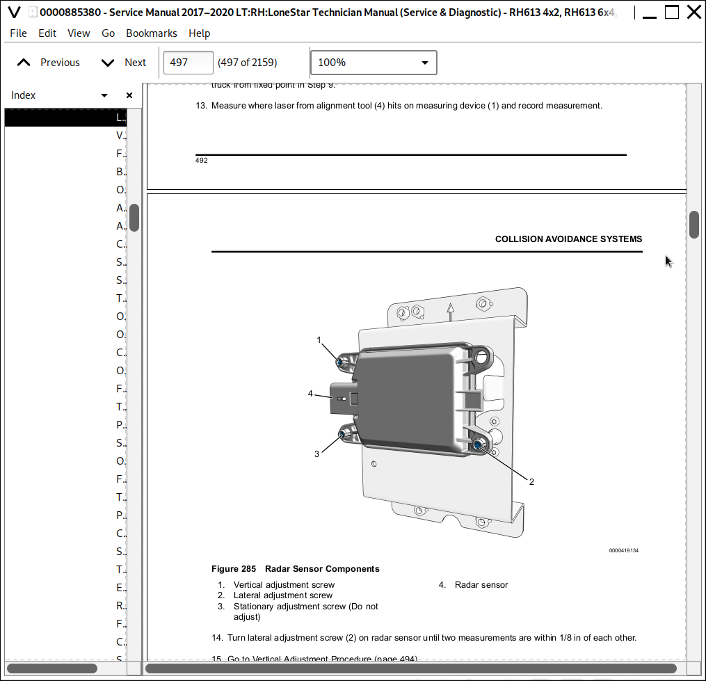
Radar Sensor Installation.......492
Special Tools.......492
Torque Specifications.......492
Equipment Conditions.......492
Installation Procedure.......492
Follow-On Procedure.......493
Radar Sensor Adjustment.......494
Special Tools.......494
Equipment Conditions.......494
Lateral Adjustment Procedure (Radar or Mounting Plate Not Replaced).......494
Lateral Adjustment Procedure (Radar or Mounting Plate Replaced).......496
Vertical Adjustment Procedure.......498
Follow-On Procedure.......500
Bendix Wingman Fusion.......501
Overview.......501
Adaptive Cruise Control (ACC).......503
Alerts.......503
Collision Mitigation Braking.......504
SafetyDirect Capability.......504
Stationary Vehicle Braking (SVB).......504
Tech Tips.......506
Operational Checkout Procedure.......507
Overview.......507
Camera Sensor Loss of Communication.......510
Overview.......510
Fault Facts.......510
Tools Required.......510
Possible Causes.......510
SafetyDirect Module Loss of Communication.......513
Overview.......513
Fault Facts.......513
Tools Required.......513
Possible Causes.......513
Camera Removal.......516
Special Tools.......516
Torque Specifications.......516
Equipment Conditions.......516
Removal Procedure.......516
Follow-On Procedure.......517
Camera Installation.......518
Special Tools.......518
Torque Specifications.......518
Equipment Conditions.......518
Installation Procedure.......518
Follow-On Procedure.......519
SafetyDirect Module High Roof Removal.......520
Special Tools.......520
Torque Specifications.......520
Equipment Conditions.......520
Removal Procedure.......520
Follow-On Procedure.......522
SafetyDirect Module High Roof Installation.......523
Special Tools.......523
Equipment Conditions.......523
Installation Procedure.......523
Follow-On Procedure.......525
SafetyDirect Module Low Roof Removal.......526
Special Tools.......526
Torque Specifications.......526
Equipment Conditions.......526
Removal Procedure.......526
Follow-On Procedure.......526
SafetyDirect Module Low Roof Installation.......527
Special Tools.......527
Torque Specifications.......527
Equipment Conditions.......527
Installation Procedure.......527
Follow-On Procedure.......527
Lane Departure System.......528
Bendix AutoVue 3G.......528
Overview.......528
6. Engine.......530
Cummins Diagnostics.......530
Table Of Contents.......530
Fault Code Diagnostics.......531
Fault Code List.......531
SPN 110 FMI 0 (Cummins FC 151) - Engine Coolant Temperature - Data Valid But Above Normal Operating Range - Most Severe Level.......533
Fault Overview.......533
Lamp Reaction.......533
Fault Fact.......533
Cummins Solutions.......533
Engine component coolant leaks.......533
Externally obstructed radiator.......533
Radiator shutters malfunctioning (If Equipped).......533
Fan Clutch operates incorrectly.......533
Stuck in - range Engine Coolant Temperature Sensor.......533
Thermostat is stuck open or closed.......533
Combustion gasses entering the cooling system.......533
Internally leaking EGR Cooler.......533
Engine Control Module (ECM) calibration revision history check.......533
SPN 111 FMI 3 (Cummins FC 195) - Coolant Level Sensor 1 Circuit - Voltage Above Normal or Shorted to High Source.......534
Fault Overview.......534
Lamp Reaction.......534
Fault Fact.......534
Cummins Solutions.......534
Fault Code 195 triggered by another Fault Code.......534
Engine Coolant Level sensor voltage circuit check (3 - wire sensor).......534
Malfunctioning Engine Coolant Level sensor circuit response (3 - wire).......534
Malfunctioning Engine Coolant Level sensor circuit response (2 - wire).......534
Engine Coolant Level sensor signal or return open circuit.......534
Engine Coolant Level sensor signal pin shorted to another pin.......534
SPN 111 FMI 18 (Cummins FC 197) - Coolant Level - Data Valid But Below Normal Operating Range - Moderately Severe Level.......535
Fault Overview.......535
Lamp Reaction.......535
Fault Fact.......535
Cummins Solutions.......535
Verify coolant loss complaint.......535
Missing or damaged Coolant Level Sensor.......535
Engine component coolant leaks.......535
Internally leaking EGR Cooler.......535
Engine Control Module (ECM) calibration revision history check.......535
SPN 111 FMI 1 (Cummins FC 235) - Coolant Level - Data Valid But Below Normal Operating Range - Most severe Level .......536
Fault Overview.......536
Lamp Reaction.......536
Fault Fact.......536
Cummins Solutions.......536
Verify coolant loss complaint.......536
Missing or damaged Coolant Level Sensor.......536
Engine component coolant leaks.......536
Internally leaking EGR Cooler.......536
Malfunctioning cooling system Pressure Cap.......536
Engine Control Module (ECM) calibration revision history check.......536
SPN 629 FMI 12 (Cummins FC 343) - Engine Control Module Warning Internal Hardware Failure - Bad Intelligent Device or Component.......537
Fault Overview.......537
Lamp Reaction.......537
Fault Fact.......537
Cummins Solutions.......537
Malfunctioning battery or battery cables.......537
Battery circuit fuse has open circuit.......537
Keyswitch input circuit check.......537
Malfunctioning charging system alternator.......537
Engine Control Module (ECM) calibration history check.......537
SPN 639 FMI 9 (Cummins FC 427) - J1939 Data Link - Abnormal Update Rate .......538
Fault Overview.......538
Lamp Reaction.......538
Fault Fact.......538
Cummins Solutions.......538
Incorrect ECM data link communications.......538
Engine Control Module (ECM) calibration revision history check.......538
SPN 168 FMI 16 (Cummins FC 442) - Battery 1 Voltage - Data Valid But Above Normal Operating Range - Moderately Severe Level.......539
Fault Overview.......539
Lamp Reaction.......539
Fault Fact.......539
Cummins Solutions.......539
Malfunctioning battery or battery cables.......539
Malfunctioning charging system alternator.......539
Engine Control Module (ECM) calibration revision history check.......539
SPN 3597 FMI 2 (Cummins FC 1117) - ECM Low Battery Voltage.......540
Fault Overview.......540
Lamp Reaction.......540
Fault Fact.......540
Cummins Solutions.......540
Battery Power Removed by Battery Power Disconnect Switch.......540
Low Battery Voltage.......540
Malfunctioning Battery or Battery Cables.......540
Battery Circuit Fuse has Open Circuit.......540
Keyswitch Input Circuit Check.......540
Intermittent Ground Connection.......540
Engine Control Module (ECM) Calibration Revision History Check.......540
ECM is Malfunctioning.......540
SPN 1761 FMI 1 (Cummins FC 1673) - Aftertreatment 1 Diesel Exhaust Fluid Tank Level - Data Valid But Below Normal Operating Range - Most Severe Level.......541
Fault Overview.......541
Associated Faults.......541
Fault Facts.......541
Possible Causes.......541
SPN 1761 FMI 3 (Cummins FC 1669) - Aftertreatment 1 Diesel Exhaust Fluid Tank Level Sensor Circuit - Voltage Above Normal or Shorted to High Source.......542
Fault Overview.......542
Associated Faults.......542
Fault Facts.......542
Possible Causes.......542
SPN 1761 FMI 4 (Cummins FC 1668) - Aftertreatment 1 Diesel Exhaust Fluid Tank Level Sensor Circuit - Voltage Below Normal or Shorted to Low Source.......543
Fault Overview.......543
Associated Faults.......543
Fault Facts.......543
Possible Causes.......543
SPN 1761 FMI 9 (Cummins FC 4677) Aftertreatment 1 Diesel Exhaust Fluid Tank Level - Abnormal Update Rate .......544
Fault Overview.......544
Associated Faults.......544
Fault Facts.......544
Possible Cause.......544
Pin-Point Tests (SPN 1761 FMI 9).......547
Tools Required.......547
SPN 1761 FMI 10 (Cummins FC 4769) - Aftertreatment 1 Diesel Exhaust Fluid Tank Level Sensor - Abnormal Rate of Change.......552
Fault Overview.......552
Associated Faults.......552
Fault Facts.......552
Possible Causes.......552
SPN 1761 FMI 11 (Cummins FC 4739) - Aftertreatment 1 Diesel Exhaust Fluid Tank Level Sensor - Root Cause Not Known.......553
Fault Overview.......553
Associated Faults.......553
Fault Facts.......553
Possible Causes.......553
SPN 1761 FMI 13 (Cummins FC 4732) - Aftertreatment 1 Diesel Exhaust Fluid Tank Level Sensor - Out of Calibration.......554
Fault Overview.......554
Associated Faults.......554
Fault Facts.......554
Possible Causes.......554
SPN 1761 FMI 17 (Cummins FC 3497) - Aftertreatment 1 Diesel Exhaust Fluid Tank Level - Data Valid But Below Normal Operating Range - Least Severe Level.......555
Fault Overview.......555
Associated Faults.......555
Fault Facts.......555
Possible Causes.......555
SPN 1761 FMI 18 (Cummins FC 3498) - Aftertreatment 1 Diesel Exhaust Fluid Tank Level - Data Valid But Below Normal Operating Range -Moderately Severe Level .......556
Fault Overview.......556
Associated Faults.......556
Fault Facts.......556
Possible Causes.......556
SPN 3031 FMI 2 (Cummins FC 1679) - Aftertreatment 1 Diesel Exhaust Fluid Tank Temperature - Data Erratic, Intermittent, or Incorrect.......557
Fault Overview.......557
Associated Faults.......557
Fault Facts.......557
Possible Causes.......557
SPN 3031 FMI 3 (Cummins FC 1678) - Aftertreatment 1 Diesel Exhaust Fluid Tank Temperature Sensor - Voltage Above Normal or Shorted to High Source .......558
Fault Overview.......558
Associated Faults.......558
Fault Facts.......558
Possible Causes.......558
SPN 3031 FMI 4 (Cummins FC 1677) - Aftertreatment 1 Diesel Exhaust Fluid Tank Temperature Sensor - Voltage Below Normal or Shorted to Low Source.......559
Fault Overview.......559
Associated Faults.......559
Fault Facts.......559
Possible Causes.......559
SPN 3031 FMI 9 (Cummins FC 4572) - Aftertreatment 1 Diesel Exhaust Fluid Tank Temperature - Abnormal Update Rate.......560
Fault Overview.......560
Associated Faults.......560
Fault Facts.......560
Possible Cause.......560
Pin-Point Tests (SPN 3031 FMI 9).......563
Tools Required.......563
SPN 3031 FMI 11 (Cummins FC 4737) - Aftertreatment 1 Diesel Exhaust Fluid Tank Temperature - Root Cause Not Known.......568
Fault Overview.......568
Associated Faults.......568
Fault Facts.......568
Possible Causes.......568
SPN 3031 FMI 13 (Cummins FC 4731) - Aftertreatment 1 Diesel Exhaust Fluid Tank Temperature Sensor - Out of Calibration.......569
Fault Overview.......569
Associated Faults.......569
Fault Facts.......569
Possible Causes.......569
SPN 3364 FMI 2 (Cummins FC 3878) - Aftertreatment Diesel Exhaust Fluid Quality - Data Erratic, Intermittent, or Incorrect.......570
Fault Overview.......570
Associated Faults.......570
Fault Facts.......570
Possible Causes.......570
SPN 3364 FMI 3 (Cummins FC 1686) - Aftertreatment Diesel Exhaust Fluid Quality Sensor Circuit - Voltage Above Normal or Shorted to High Source.......571
Fault Overview.......571
Associated Faults.......571
Fault Facts.......571
Possible Cause.......571
SPN 3364 FMI 4 (Cummins 1685) - Aftertreatment Diesel Exhaust Fluid Quality Sensor Circuit - Voltage Below Normal or Shorted to Low Source.......573
Fault Overview.......573
Associated Faults.......573
Fault Facts.......573
Possible Cause.......573
SPN 3364 FMI 9 (Cummins FC 3868) - Aftertreatment Diesel Exhaust Fluid Quality - Abnormal Update Rate.......575
Fault Overview.......575
Associated Faults.......575
Fault Facts.......575
Possible Cause.......575
Pin-Point Tests (SPN 3364 FMI 9).......578
Tools Required.......578
SPN 3364 FMI 10 (Cummins FC 4277) - Aftertreatment Diesel Exhaust Fluid Quality - Abnormal Rate of Change .......583
Fault Overview.......583
Associated Faults.......583
Fault Facts.......583
Possible Causes.......583
SPN 3364 FMI 11 (Cummins FC 1715) - Aftertreatment Diesel Exhaust Fluid Quality - Root Cause Not Known.......585
Fault Overview.......585
Associated Faults.......585
Fault Facts.......585
Possible Causes.......585
SPN 3364 FMI 13 (Cummins FC 1714) - Aftertreatment Diesel Exhaust Fluid Quality - Out of Calibration.......586
Fault Overview.......586
Associated Faults.......586
Fault Facts.......586
Possible Causes.......586
SPN 3364 FMI 15 (Cummins FC 4842) - Aftertreatment Diesel Exhaust Fluid Quality - Data Valid But Above Normal Operating Range - Least Severe Level.......587
Fault Overview.......587
Associated Faults.......587
Fault Facts.......587
Possible Causes.......587
SPN 3364 FMI 18 (Cummins FC 3867) - Aftertreatment Diesel Exhaust Fluid Quality - Data Valid But Below Normal Operating Range - Moderately Severe Level.......589
Fault Overview.......589
Associated Faults.......589
Fault Facts.......589
Possible Causes.......589
SPN 3521 FMI 11 (Cummins FC 4768) - Aftertreatment 1 Diesel Exhaust Fluid Property - Root Cause Not Known.......591
Fault Overview.......591
Associated Faults.......591
Fault Facts.......591
Possible Causes.......591
SPN 3521 FMI 16 (Cummins FC 6765) - Aftertreatment Diesel Exhaust Fluid Property - Data Valid But Above Normal Operating Range - Moderately Severe Level.......592
Fault Overview.......592
Associated Faults.......592
Fault Facts.......592
Possible Causes.......592
SPN 3521 FMI 18 (Cummins FC 6766) - Aftertreatment Diesel Exhaust Fluid Property - Data Valid But Below Normal Operating Range - Moderately Severe Level.......594
Fault Overview.......594
Associated Faults.......594
Fault Facts.......594
Possible Causes.......594
SPN 3521 FMI 31 (Cummins FC 4235) - Aftertreatment 1 Diesel Exhaust Fluid Property- Condition Exists.......596
Fault Overview.......596
Associated Faults.......596
Fault Facts.......596
Possible Causes.......596
SPN 4096 FMI 31 (Cummins FC 3547) - Aftertreatment Diesel Exhaust Fluid Tank Empty - Condition Exists.......598
Fault Overview.......598
Associated Faults.......598
Fault Facts.......598
Possible Causes.......598
Tests and Inspections.......600
Overview.......600
DEF Head Unit Coolant Line Routing Inspection.......601
Overview.......601
Tools Required.......601
Equipment Condition.......601
Inspection Procedure.......601
Expected Outcome.......602
DEF Quality Test.......603
Overview.......603
Tools Required.......603
Equipment Condition.......603
Test Procedure.......603
Expected Outcome.......603
DEFTHV Coolant Flow Test.......604
Overview.......604
Tools Required.......604
Equipment Condition.......604
Test Setup.......604
Test Procedure.......604
Expected Outcome.......604
Engine Coolant Level Circuit Test.......605
Overview.......605
Tools Required.......605
Equipment Condition.......605
Test Setup.......605
Test Procedure.......605
ECM Battery Voltage Supply Test.......615
Overview.......615
Tools Required.......615
Equipment Condition.......615
Test Setup.......615
Test Procedure.......616
7. Exterior Lighting.......625
Air Cleaner Lighting - LoneStar.......625
Overview.......625
Air Shield Lighting.......626
Overview.......626
Brake Switch.......627
Overview.......627
Operational Checkout Procedure.......629
Overview.......629
Brake Switch Not Working.......631
Overview.......631
Fault Facts.......631
Possible Causes.......631
Pin-Point Test - Feature Code 0004092.......634
Tools Required.......634
SPN 597 FMI 0 - Brake Switch Input short to Power.......638
Overview.......638
Associated Faults.......638
Fault Facts.......638
Possible Causes.......638
Pin-Point Test - SPN 597 FMI 0 with Air Brakes 0004092.......640
Tools Required.......640
SPN 597 FMI 1 - Brake Switch Reading Below Normal Range.......644
Overview.......644
Associated Faults.......644
Fault Facts.......644
Possible Causes.......644
SPN 597 FMI 2 - Analog Brake Switch signal does not agree with Digital brake switch signal.......646
Overview.......646
Associated Faults.......646
Fault Facts.......646
Possible Causes.......646
Fog Lights.......648
Overview.......648
Operational Checkout Procedure.......650
Overview.......650
Input Diagnostics.......653
Overview.......653
Fault Facts.......653
Possible Causes.......653
Output Diagnostics - Not Illuminating.......655
Overview.......655
Fault Facts.......655
Possible Causes.......655
Pin-Point Test - Output Diagnostics - Not Illuminating.......660
Tools Required.......660
Output Diagnostics - Illuminating When Not Requested.......664
Overview.......664
Fault Facts.......664
Possible Causes.......664
Pin-Point Test - Output Diagnostics - Illuminating When Not Requested.......667
Tools Required.......667
SPN 2388 FMI 5 - Left Fog Light Open Circuit.......669
Overview.......669
Associated Faults.......669
Fault Facts.......669
Possible Causes.......669
Pin-Point Test - SPN 2388 FMI 5.......671
Tools Required.......671
SPN 2388 FMI 6 - Left Fog Light Short to Ground.......673
Overview.......673
Associated Faults.......673
Fault Facts.......673
Possible Causes.......673
Pin-Point Test - SPN 2388 FMI 6.......675
Tools Required.......675
SPN 4008 FMI 5 - Right Fog Light Open Circuit.......677
Overview.......677
Associated Faults.......677
Fault Facts.......677
Possible Causes.......677
Pin-Point Test - SPN 4008 FMI 5.......679
Tools Required.......679
SPN 4008 FMI 6 - Right Fog Light Short to Ground.......681
Overview.......681
Associated Faults.......681
Fault Facts.......681
Possible Causes.......681
Pin-Point Test - SPN 4008 FMI 6.......683
Tools Required.......683
Headlights.......685
Overview.......685
Operational Checkout Procedure.......687
Overview.......687
Special Tools.......690
Low Beam Diagnostics.......693
Overview.......693
Low Beam Input Diagnostics.......695
Overview.......695
Fault Facts.......695
Special Tools.......695
Possible Causes.......695
Low Beam Output Diagnostics - Not illuminating.......697
Overview.......697
Fault Facts.......697
Special Tools.......697
Possible Causes.......697
Low Beam Output Diagnostics - Illuminating When Not Requested.......702
Overview.......702
Fault Facts.......702
Special Tools.......702
Possible Causes.......702
SPN 2653 FMI 5 - Left Low Beam Open Circuit.......704
Overview.......704
Associated Faults.......704
Fault Facts.......704
Special Tools.......704
Possible Causes.......704
SPN 2653 FMI 6 - Left Low Beam Short to Ground.......706
Overview.......706
Associated Faults.......706
Fault Facts.......706
Special Tools.......706
Possible Causes.......706
SPN 2655 FMI 5 - Right Low Beam Open Circuit.......708
Overview.......708
Associated Faults.......708
Fault Facts.......708
Special Tools.......708
Possible Causes.......708
SPN 2655 FMI 6 - Right Low Beam Short to Ground.......710
Overview.......710
Associated Faults.......710
Fault Facts.......710
Special Tools.......710
Possible Causes.......710
High Beam Diagnostics.......711
Overview.......711
High Beam Input Diagnostics.......713
Overview.......713
Fault Facts.......713
Special Tools.......713
Possible Causes.......713
High Beam Output Diagnostics - Not Illuminating.......716
Overview.......716
Fault Facts.......716
Tools Required.......716
Possible Causes.......716
High Beam Output Diagnostics - Illuminating When Not Requested.......721
Overview.......721
Fault Facts.......721
Special Tools.......721
Possible Causes.......721
SPN 4011 FMI 5 - Left High Beam Open Circuit.......724
Overview.......724
Associated Faults.......724
Fault Facts.......724
Special Tools.......724
Possible Causes.......724
SPN 4011 FMI 6 - Left High Beam Short to Ground.......726
Overview.......726
Associated Faults.......726
Fault Facts.......726
Special Tools.......726
Possible Causes.......726
SPN 4012 FMI 5 - Right High Beam Open Circuit.......727
Overview.......727
Associated Faults.......727
Fault Facts.......727
Special Tools.......727
Possible Causes.......727
SPN 4012 FMI 6 - Right High Beam Short to Ground.......729
Overview.......729
Associated Faults.......729
Fault Facts.......729
Special Tools.......729
Possible Causes.......729
Lighting Control Module.......730
Overview.......730
Operational Checkout Procedure.......731
Overview.......731
Pin-Point Test - Operational Checkout Procedure.......733
Tools Required.......733
Marker / Park Lights.......734
Overview.......734
Operational Checkout Procedure.......738
Overview.......738
Park Light Input Diagnostics.......742
Overview.......742
Fault Facts.......742
Possible Causes.......742
Park Light Output Diagnostics - Not Illuminating.......744
Overview.......744
Fault Facts.......744
Possible Causes.......744
Pin-Point Test - Park Light Output - Not Illuminating.......747
Tools Required.......747
Park Light Output Diagnostics - Illuminating When Not Requested.......749
Overview.......749
Fault Facts.......749
Possible Causes.......749
Pin-Point Test - Park Light Output - Illuminating When Not Requested.......751
Tools Required.......751
SPN 2378 FMI 5 - Park Light Underccurrent.......753
Overview.......753
Associated Faults.......753
Fault Facts.......753
Possible Causes.......753
Pin-Point Test - SPN 2378 FMI 5.......755
Tools Required.......755
SPN 2378 FMI 6 - Park Light Overcurrent.......757
Overview.......757
Associated Faults.......757
Fault Facts.......757
Possible Causes.......757
Pin-Point Test - SPN 2378 FMI 6.......759
Tools Required.......759
SPN 4024 FMI 2 - Marker Light Interrupt Switch Failure.......761
Overview.......761
Associated Faults.......761
Fault Facts.......761
Possible Causes.......761
Stop / Turn Lights.......763
Overview.......763
Operational Checkout Procedure.......770
Overview.......770
Hazard Input Diagnostics.......775
Overview.......775
Possible Causes.......775
Pin-Point Test - Hazard Input Diagnostics.......778
Tools Required.......778
Turn Signal Input Diagnostics.......780
Overview.......780
Possible Causes.......780
Pin-Point Test - Turn Signal Input Diagnostics.......784
Tools Required.......784
Front Turn Lamps Not Illuminating.......792
Overview.......792
Possible Causes.......792
Pin-Point Test- Front Turn Lamp Output Not Illuminating.......796
Tools Required.......796
Front Turn Lamps Illuminating When Not Requested.......799
Overview.......799
Possible Causes.......799
Pin-Point Test - Front Turn Lamps Illuminating When Not Requested.......801
Tools Required.......801
Rear Turn Lamp Not Illuminating.......803
Overview.......803
Possible Causes.......803
Pin-Point Test - Stop and Turn Lamps- Rear Turn Lamp Not Illuminating.......806
Tools Required.......806
Rear Turn Lamps Illuminating When Not Requested.......809
Overview.......809
Possible Causes.......809
Pin-Point Test - Stop and Turn Lamps- Rear Turn Lamps Illuminating When Not Requested.......811
Tools Required.......811
SPN 2368 FMI 5 - Left Front Turn Lamp Undercurrent with Combined Stop and Turn Lamps.......813
Overview.......813
Associated Faults.......813
Fault Facts.......813
Possible Causes.......813
Pin-Point Test SPN 2368 FMI 5.......815
Tools Required.......815
SPN 2368 FMI 6 - Left Front Turn Lamp Overcurrent with Combined Stop and Turn Lamps.......817
Overview.......817
Associated Faults.......817
Fault Facts.......817
Possible Causes.......817
Pin-Point Test SPN 2368 FMI 6.......819
Tools Required.......819
SPN 2370 FMI 5 - Right Front Turn Lamp Undercurrent with Combined Stop and Turn Lamps.......821
Overview.......821
Associated Faults.......821
Fault Facts.......821
Possible Causes.......821
Pin-Point Test SPN 2370 FMI 5.......823
Tools Required.......823
SPN 2370 FMI 6 - Right Front Turn Lamp Overcurrent with Combined Stop and Turn Lamps.......825
Overview.......825
Associated Faults.......825
Fault Facts.......825
Possible Causes.......825
Pin-Point Test SPN 2370 FMI 6.......827
Tools Required.......827
SPN 2372 FMI 5 - Left Rear Turn Lamp Undercurrent .......829
Overview.......829
Associated Fault.......829
Fault Facts.......829
Possible Causes.......829
Pin-Point Test SPN 2372 FMI 5.......831
Tools Required.......831
SPN 2372 FMI 6 - Left Rear Turn Lamp Overcurrent .......833
Overview.......833
Associated Faults.......833
Fault Facts.......833
Possible Causes.......833
Pin-Point Test SPN 2372 FMI 6.......835
Tools Required.......835
SPN 2374 FMI 5 - Right Rear Turn Lamp Undercurrent .......837
Overview.......837
Associated Faults.......837
Fault Facts.......837
Possible Causes.......837
Pin-Point Test SPN 2374 FMI 5.......839
Tools Required.......839
SPN 2374 FMI 6 - Right Rear Turn Lamp Overcurrent .......841
Overview.......841
Associated Faults.......841
Fault Facts.......841
Possible Causes.......841
Pin-Point Test SPN 2374 FMI 6.......843
Tools Required.......843
8. HVAC.......845
On-Highway HVAC System.......845
Front HVAC System.......846
Overview.......846
A/C Refrigerant Flow.......848
General Operation of HVAC Electrical System.......850
Air Distribution.......851
Defrost.......851
Temperature.......851
Recirculation.......852
Panel / Floor.......852
Operational Checkout Procedure.......854
Overview.......854
Blower Not Working Properly.......857
Overview.......857
Fault Facts.......857
Special Tools.......857
Possible Causes.......857
HVAC System Air Not Cool After A/C Turned ON.......862
Overview.......862
Fault Facts.......862
Possible Causes.......862
HVAC System Air Not Warm After Heat Turned ON.......867
Overview.......867
Possible Causes.......867
SPN 876 FMI 5 - HVAC Compressor Clutch Engagement Undercurrent.......869
Overview.......869
Associated Faults.......869
Fault Facts.......869
Possible Causes.......869
SPN 876 FMI 6 - HVAC Compressor Clutch Engagement Overcurrent.......870
Overview.......870
Associated Faults.......870
Fault Facts.......870
Possible Causes.......870
SPN 1552 FMI 2 - Temperature Door Actuator Data Intermittent or Incorrect.......871
Overview.......871
Associated Faults.......871
Fault Facts.......871
Possible Causes.......871
SPN 2609 FMI 0 - PT Sensor - HVAC Pressure Sensor Reading Above Normal Range.......872
Overview.......872
Associated Faults.......872
Fault Facts.......872
Tools Required.......872
Possible Causes.......872
SPN 2609 FMI 1 - PT Sensor - HVAC Pressure Sensor Reading Below Normal Range.......874
Overview.......874
Associated Faults.......874
Fault Facts.......874
Tools Required.......874
Possible Causes.......874
SPN 2609 FMI 15 - PT Sensor - HVAC Low Pressure Protection (A/C Compressor Lockout).......877
Overview.......877
Associated Faults.......877
Fault Facts.......877
SPN 2609 FMI 16 - PT Sensor - HVAC High Pressure Protection.......878
Overview.......878
Associated Faults.......878
Fault Facts.......878
Possible Causes.......878
SPN 3981 FMI 2 - Defrost Door Actuator Data Intermittent or Incorrect.......880
Overview.......880
Associated Faults.......880
Fault Facts.......880
Possible Causes.......880
SPN 3984 FMI 2 - Recirculation Door Actuator Data Intermittent or Incorrect.......881
Overview.......881
Associated Faults.......881
Fault Facts.......881
Possible Causes.......881
SPN 3985 FMI 9 - HVAC Control Module Circuit Failed To Communicate With the Body Control Module.......882
Overview.......882
Associated Faults.......882
Fault Facts.......882
Possible Causes.......882
SPN 516636 FMI 19 - Error or Not Available is transmitted from Front HVAC Control Module.......883
Overview.......883
Associated Faults.......883
Fault Facts.......883
Tools Required.......883
Possible Causes.......883
SPN 516778 FMI 5 - Freeze Probe Open Circuit.......885
Overview.......885
Associated Faults.......885
Fault Facts.......885
Tools Required.......885
Possible Causes.......885
SPN 516778 FMI 6 - Freeze Probe Short to Ground.......886
Overview.......886
Associated Faults.......886
Fault Facts.......886
Tools Required.......886
Possible Causes.......886
SPN 516825 FMI 2 - Panel Door Actuator Data Intermittent or Incorrect.......888
Overview.......888
Associated Faults.......888
Fault Facts.......888
Possible Causes.......888
SPN 516826 FMI 2 - Floor Door Actuator Data Intermittent or Incorrect.......889
Overview.......889
Associated Faults.......889
Fault Facts.......889
Possible Causes.......889
SPN 516827 FMI 3 - Blower Motor Under Voltage Protection.......890
Overview.......890
Associated Faults.......890
Fault Facts.......890
Tools Required.......890
Possible Causes.......890
SPN 516827 FMI 4 - Blower Over Voltage Protection.......892
Overview.......892
Associated Faults.......892
Fault Facts.......892
Tools Required.......892
Possible Causes.......892
SPN 516827 FMI 7 - Blower Motor Not Responding (Blocked Rotor).......894
Overview.......894
Associated Faults.......894
Fault Facts.......894
Tools Required.......894
Possible Causes.......894
SPN 516827 FMI 31 - Blower Motor Over Temperature.......896
Overview.......896
Associated Faults.......896
Fault Facts.......896
Tools Required.......896
Possible Causes.......896
SPN 520465 FMI 2 - HVAC Control Module - Multiple Actuator Faults.......898
Overview.......898
Associated Faults.......898
Fault Facts.......898
Tools Required.......898
Possible Causes.......898
Sleeper / Rear HVAC System.......900
Overview.......900
A/C Refrigerant Flow.......903
Rear Air Distribution.......904
Sleeper HVAC Operational Checkout Procedure.......905
Overview.......905
Rear HVAC System Air Not Cool After A/C Turned ON.......910
Overview.......910
Fault Facts.......910
Possible Causes.......910
HVAC Tests.......912
Overview.......912
A/C Compressor Clutch Electrical Test.......914
Overview.......914
Tools Required.......914
Equipment Condition.......914
Test Setup.......914
Test Procedure.......914
Expected Outcome.......916
Follow On Procedure.......916
A/C System Restriction Test.......917
Overview.......917
Tools Required.......917
Equipment Condition.......917
Test Setup.......917
Test Procedure.......917
Expected Outcome.......917
Charge Quantity Measurement Test.......918
Overview.......918
Tools Required.......918
Equipment Condition.......918
Test Setup.......918
Test Procedure.......918
Expected Outcome.......918
Refrigerant Leak Test.......919
Overview.......919
Tools Required.......919
Equipment Condition.......919
Test Procedure Refrigerant Present.......920
No Refrigerant Present.......921
No Refrigerant Present - High Pressure Nitrogen.......922
Expected Outcome.......923
Follow-On Procedure.......923
Refrigerant Identification Test.......924
Overview.......924
Tools Required.......924
Equipment Condition.......924
Test Setup.......924
Test Procedure.......924
Expected Outcome.......924
Follow-On Procedure.......924
Static Refrigerant Pressure Test.......925
Overview.......925
Tools Required.......925
Equipment Condition.......925
Test Setup.......925
Test Procedure.......925
Expected Outcome.......926
Follow On Procedure.......926
Dynamic Refrigerant Pressure Test.......927
Overview.......927
Tools Required.......927
Equipment Condition.......927
Test Setup.......928
Test Procedure.......928
Expected Outcome.......930
Follow-On Procedure.......930
A/C Pressure Readings Indicating Problems.......931
Overview.......931
Tools Required.......931
Equipment Condition.......931
Low-Side Pressure Low, High-Side Pressure Low.......932
Possible Causes.......932
Low-Side Pressure Low, High-Side Pressure Normal or High.......933
Possible Causes.......933
High-Side and Low-Side Pressures Normal or Slightly Low, Duct Output Not Cold.......934
Possible Causes.......934
Low-Side Pressure Normal, High-Side Pressure High.......935
Possible Causes.......935
Low-Side Pressure High, High-Side Pressure Low.......936
Possible Causes.......936
Low-Side Pressure High, High-Side Pressure Normal.......937
Possible Causes.......937
Low-Side Pressure High, High-Side Pressure High.......938
Possible Causes.......938
High-Side Pressure Excessively High or Low.......938
A/C Compressor Compression Test.......939
Overview.......939
Tools Required.......939
Equipment Condition.......939
Test Procedure.......939
Expected Outcome.......939
HVAC Control Module and Actuator Calibration.......940
Overview.......940
Defrost Actuator Electrical Test.......941
Overview.......941
Fault Facts.......941
Possible Causes.......941
Pin-Point Test - Defrost Actuator Electrical Test.......944
Tools Required.......944
Floor Actuator Electrical Test.......949
Overview.......949
Fault Facts.......949
Possible Causes.......949
Pin-Point Test - Floor Actuator Electrical Test.......952
Tools Required.......952
Panel Actuator Electrical Test.......957
Overview.......957
Fault Facts.......957
Possible Causes.......957
Pin-Point Test - Panel Actuator Electrical Test.......960
Tools Required.......960
Recirculation Actuator Electrical Test.......965
Overview.......965
Fault Facts.......965
Possible Causes.......965
Pin-Point Test - Recirculation Actuator Electrical Test.......968
Tools Required.......968
Temperature Actuator Electrical Test.......973
Overview.......973
Fault Facts.......973
Possible Causes.......973
Pin-Point Test - Temperature Actuator Electrical Test.......976
Tools Required.......976
Blower Motor Electrical Input Test.......981
Overview.......981
Tools Required.......981
Equipment Condition.......981
Test Setup.......981
Test Procedure.......981
Expected Outcome.......981
Follow On Procedure.......981
HVAC Control Module Electrical Tests.......982
Overview.......982
Tools Required.......982
Equipment Condition.......982
Test Setup.......982
Test Procedure.......982
Expected Outcome.......984
Follow On Procedure.......984
Freeze Probe Electrical Test.......985
Overview.......985
Tools Required.......985
Equipment Condition.......985
Test Setup.......985
Test Procedure.......985
Expected Outcome.......986
Follow-On Procedure.......986
Heater Core Seal Leak Test.......987
Overview.......987
Tools Required.......987
Equipment Condition.......987
Test Setup.......987
Test Procedure.......988
Expected Outcome.......989
Follow On Procedure.......989
Low A/C Pressure Sensor Electrical Test.......990
Overview.......990
Tools Required.......990
Equipment Condition.......990
Test Setup.......990
Test Procedure.......990
Expected Outcome.......990
Follow On Procedure.......990
HVAC Pressure / Temperature Sensor Electrical Test.......991
Overview.......991
Tools Required.......991
Equipment Condition.......991
Test Setup.......991
Pressure / Temperature Test Procedure.......991
Expected Outcome.......993
Follow On Procedure.......993
HVAC Pressure / Temperature Sensor Functional Test.......994
Overview.......994
Tools Required.......994
Equipment Condition.......994
Test Setup.......994
Procedure.......994
Expected Outcome.......995
Sleeper HVAC Input Test.......996
Overview.......996
Tools Required.......996
Equipment Condition.......996
Test Setup.......996
Test Procedure.......997
Expected Outcome.......998
Follow On Procedure.......998
Rear A/C Request Test.......999
Overview.......999
Tools Required.......999
Equipment Condition.......999
Test Setup.......999
Test Procedure.......999
Expected Outcome.......1000
Follow On Procedure.......1000
Rear HVAC Control Module and Blend Door Actuator Calibration.......1001
Overview.......1001
Tools Required.......1001
Equipment Condition.......1001
Test Setup.......1001
Test Procedure.......1001
Expected Outcome.......1002
Follow-On Procedure.......1002
Rear Blend Door Actuator Electrical Test.......1003
Overview.......1003
Tools Required.......1003
Equipment Condition.......1003
Test Setup.......1003
Test Procedure.......1003
Expected Outcome.......1004
Follow-On Procedure.......1004
Rear Blend Door Movement Test.......1005
Overview.......1005
Tools Required.......1005
Equipment Condition.......1005
Test Setup.......1005
Test Procedure.......1005
Expected Outcome.......1005
Follow-On Procedure.......1005
Sleeper HVAC Blower Speed Switch Electrical Test.......1006
Overview.......1006
Tools Required.......1006
Equipment Condition.......1006
Test Setup.......1006
Test Procedure.......1006
Expected Outcome.......1008
Follow-On Procedure.......1008
Rear Blower Motor Electrical Test.......1009
Overview.......1009
Tools Required.......1009
Equipment Condition.......1009
Test Setup.......1009
Test Procedure.......1009
Expected Outcome.......1011
Follow-On Procedure.......1011
Rear HVAC Control Module Electrical Test.......1012
Overview.......1012
Tools Required.......1012
Equipment Condition.......1012
Test Setup.......1012
Test Procedure.......1012
Expected Outcome.......1013
Follow-On Procedure.......1013
Sleeper HVAC Temperature Control Switch Electrical Tests.......1014
Overview.......1014
Tools Required.......1014
Equipment Condition.......1014
Test Setup.......1014
Test Procedure.......1014
Expected Outcome.......1016
Rear Discharge Duct Temperature Sensor Electrical Test.......1017
Overview.......1017
Tools Required.......1017
Equipment Condition.......1017
Test Setup.......1017
Test Procedure.......1017
Expected Outcome.......1017
Follow-On Procedure.......1017
HVAC Inspections.......1018
Overview.......1018
HVAC System Inspection.......1019
Overview.......1019
Tools Required.......1019
Equipment Condition.......1019
Inspection Procedure.......1019
Expected Outcome.......1020
A/C System Internal Damage Inspection.......1021
Overview.......1021
Tools Required.......1021
Equipment Condition.......1021
Inspection Procedure.......1021
Expected Outcome.......1022
Rear HVAC System Inspection.......1023
Overview.......1023
Tools Required.......1023
Equipment Condition.......1023
Inspection Procedure.......1023
Expected Outcome.......1024
No Idle HVAC.......1025
Eberspaecher Auxiliary Heater.......1026
Overview.......1026
Regular Maintenance.......1027
Monthly.......1027
Every 1000 operating hours.......1028
Connecting EDiTH to heater.......1029
Starting and using EDiTH software.......1029
Reading fault codes.......1035
Clearing fault codes.......1035
Removing controller lock.......1036
Symptom Diagnostics.......1037
Overview.......1037
Fault Code Diagnostics.......1039
Overview.......1039
10 - Overvoltage / Shutdown.......1041
Fault Code Overview.......1041
11 - Undervoltage / Shutdown.......1042
Fault Code Overview.......1042
Pin-Point Tests.......1044
Tools Required.......1044
12 - Overheating.......1045
Fault Code Overview.......1045
14 - Possible Overheating Detected (Differential Evaluation).......1046
Fault Code Overview.......1046
15 - Operation Lock - Heater has Overheated More than 10 Times.......1047
Fault Code Overview.......1047
17 - Overheating - Emergency Off.......1048
Fault Code Overview.......1048
20 - Glow Plug - Interruption.......1049
Fault Code Overview.......1049
Pin-Point Tests.......1050
Tools Required.......1050
21 - Glow Plug Output: Short Circuit, Overload or Accidental Ground.......1051
Fault Code Overview.......1051
30 - Speed of Combustion Fan motor Outside Tolerance Range.......1052
Fault Code Overview.......1052
31 - Combustion Fan Motor Open Circuit.......1053
Fault Code Overview.......1053
Pin-Point Tests.......1054
Tools Required.......1054
32 - Combustion Fan Motor Short Circuit, Overload or Accidental Ground.......1055
Fault Code Overview.......1055
39 - Vehicle Blower Relay Control - Short Circuit, Overload or Earth Short.......1056
Fault Code Overview.......1056
41 - Water Pump - Interruption.......1057
Fault Code Overview.......1057
Pin-Point Tests.......1058
Tools Required.......1058
42 - Water Pump - Short Circuit, Overload or Earth Short.......1059
Fault Code Overview.......1059
Pin-Point Tests.......1060
Tools Required.......1060
47 - Metering Pump - Short Circuit, Overload or Earth Short.......1061
Fault Code Overview.......1061
Pin-Point Tests.......1063
Tools Required.......1063
48 - Metering Pump Interruption.......1064
Fault Code Overview.......1064
50 - Operation Lock Because of Too Many Failed Starting Attempts.......1065
Fault Code Overview.......1065
51 - Time Exceeded - Blowing Cold.......1066
Fault Code Overview.......1066
52 - Safety Time Exceeded.......1067
Fault Code Overview.......1067
53 - Flame Aborted from Control Stage Large.......1069
Fault Code Overview.......1069
54 - Flame Aborted from Control Stage Boost.......1070
Fault Code Overview.......1070
56 - Flame Aborted from Control Stage Small.......1071
Fault Code Overview.......1071
60 - Temperature Sensor - Interruption.......1072
Fault Code Overview.......1072
61 - Temperature Sensor - Short-Circuit, Overload or Accidental Ground.......1073
Fault Code Overview.......1073
64 - Flame Sensor - Interruption.......1074
Fault Code Overview.......1074
65 - Flame Sensor - Short-Circuit, Overload or Accidental Ground.......1075
Fault Code Overview.......1075
71 - Overheating Sensor - Interruption.......1076
Fault Code Overview.......1076
72 - Overheating Sensor - Short-Circuit, Overload or Accidental Ground.......1077
Fault Code Overview.......1077
90 - Controller Defect.......1078
Fault Code Overview.......1078
91 - External Interference Voltage.......1079
Fault Code Overview.......1079
92 - Controller Defect.......1080
Fault Code Overview.......1080
93 - Controller Defect.......1081
Fault Code Overview.......1081
94 - Controller Defect.......1082
Fault Code Overview.......1082
95 - Controller Defect.......1083
Fault Code Overview.......1083
96 - Controller Defect.......1084
Fault Code Overview.......1084
97 - Controller Defect.......1085
Fault Code Overview.......1085
98 - Controller Defect.......1086
Fault Code Overview.......1086
99 - Controller Defect.......1087
Fault Code Overview.......1087
100 - Controller Defect.......1088
Fault Code Overview.......1088
101 - Controller Defect.......1089
Fault Code Overview.......1089
Tests and Inspections.......1090
Blower Motor Test.......1090
Tools Required.......1090
Test Setup.......1090
Test Procedure.......1090
Expected Outcome.......1090
Coolant Circuit Inspection.......1091
Inspection Setup.......1091
Inspection Procedure.......1091
Expected Outcome.......1091
Connector Inspection.......1092
Inspection Setup.......1092
Inspection Procedure.......1092
Expected Outcome.......1092
Flame Sensor Test.......1093
Tools Required.......1093
Test Setup.......1093
Test Procedure.......1093
Expected Outcome.......1093
Fuel Intake Inspection.......1095
Inspection Setup.......1095
Inspection Procedure.......1095
Expected Outcome.......1095
Fuel Pump Quantity Test.......1096
Tools Required.......1096
Test Setup.......1096
Test Procedure.......1096
Expected Outcome.......1097
Glow Pin Test.......1098
Tools Required.......1098
Test Setup.......1098
Test Procedure.......1098
Expected Outcome.......1098
Glow Plug Filter Inspection.......1099
Inspection Setup.......1099
Inspection Procedure.......1099
Expected Outcome.......1099
Follow-on Procedure.......1099
Intake and exhaust air Inspection.......1100
Inspection Setup.......1100
Inspection Procedure.......1100
Expected Outcome.......1100
Integrated Fuel Filter Inspection.......1101
Inspection Setup.......1101
Inspection Procedure.......1101
Expected Outcome.......1101
Overheat Sensor Test.......1102
Tools Required.......1102
Test Setup.......1102
Test Procedure.......1102
Expected Outcome.......1103
Temperature Sensor Test.......1104
Tools Required.......1104
Test Setup.......1104
Test Procedure.......1104
Expected Outcome.......1104
Removal and Install Procedures.......1106
Blower motor.......1106
Removal.......1106
Installation.......1107
Blower Motor Cover.......1108
Removal.......1108
Installation.......1108
Controller.......1109
Removal.......1109
Installation.......1110
Flame Sensor.......1111
Removal.......1111
Installation.......1111
Fuel Pump.......1112
Removal.......1112
Installation.......1113
Torque Specifications.......1113
Glow Pin Screen.......1114
Removal.......1114
Installation.......1114
Torque Specifications.......1114
Glow Plug.......1115
Removal.......1115
Installation.......1115
Heat Exchanger Cover.......1116
Removal.......1116
Installation.......1116
Overheat / Temperature Sensor Assembly.......1117
Removal.......1117
Installation.......1117
Torque Specifications.......1117
Water Pump.......1118
Removal.......1118
Installation.......1118
Diagnostic Tools and Accessories.......1119
ESP2029007050280Z - Y Adapter.......1119
ESP2215241890000Z - ISO Adapter.......1119
TXT126870334 Terminal release tool.......1120
TXT126870335 Terminal release tool.......1120
ZTSE4357 Digital Multimeter (DMM).......1121
ZTSE4435C - International Electronic Engine Terminal Test Kit.......1122
ZTSE44983 - Banana Plug Harness.......1122
ZTSE4871 - Breakout Harness 4871.......1123
9. Instrumentation / Gauges.......1124
Overview.......1124
Gauge Cluster.......1126
EGC Fault Reaction.......1126
Virtual Gauges.......1126
Auxiliary Gauges.......1126
Operational Checkout Procedure.......1130
Gauges.......1131
Air Pressure Gauges.......1131
Overview.......1131
Air Application Gauge.......1135
Overview.......1135
Axle Temperature Gauge.......1139
Overview.......1139
DEF Gauges.......1143
Overview.......1143
Engine Coolant Temperature.......1145
Overview.......1145
Engine Manifold Pressure .......1147
Overview.......1147
Engine Oil Pressure.......1149
Overview.......1149
Engine Oil Temperature .......1151
Overview.......1151
Fuel Level Gauge .......1153
Overview.......1153
Outside Temperature Monitor.......1157
Overview.......1157
PTO Indicator.......1159
Overview.......1159
Rear Axle Load Monitor.......1160
Overview.......1161
Speedometer.......1165
Overview.......1165
Tachometer.......1167
Overview.......1167
Transmission Oil Temp Gauge.......1168
Manual.......1168
Overview.......1168
Automatic.......1172
Overview.......1172
Voltmeter.......1173
Overview.......1173
Instrumentation.......1175
ABS Indicator .......1175
Air Cleaner Restriction.......1176
Overview.......1176
Brake Warning Indicator.......1180
Overview.......1180
DPF Indicator.......1181
Overview.......1181
Electronic Stability Control (ESC) Indicator.......1183
Overview.......1183
High Exhaust System Temperature Indicator.......1184
Overview.......1184
Park Brake Indicator.......1186
Overview.......1186
Tire Pressure Monitor System.......1190
Overview.......1190
Traction Control Indicator.......1192
Overview.......1193
Trailer ABS Indicator.......1196
Overview.......1196
Transmission Indicator.......1197
Overview.......1197
Up-Shift Indicator.......1198
Overview.......1198
Driver Information Display.......1200
Overview.......1200
10. Seats.......1202
RollTek Supplemental Restraint System (SRS).......1202
Overview.......1202
Operational Check.......1205
Symptoms.......1206
Diagnostics.......1207
11. Trailer.......1208
Trailer Lighting.......1208
Overview.......1208
Operational Checkout Procedure.......1210
Overview.......1210
Fault Facts.......1210
Special Tools.......1211
Trailer Marker Lights - Not Illuminating.......1214
Overview.......1214
Fault Facts.......1214
Special Tools.......1214
Possible Causes.......1214
Trailer Tail Lights - Not Illuminating.......1216
Overview.......1216
Fault Facts.......1216
Special Tools.......1216
Possible Causes.......1216
Trailer Left Turn Lights - Not Illuminating.......1218
Overview.......1218
Fault Facts.......1218
Special Tools.......1218
Possible Causes.......1218
Trailer Right Turn Lights - Not Illuminating.......1220
Overview.......1220
Fault Facts.......1220
Special Tools.......1220
Possible Causes.......1220
Trailer Stop Lights - Not Illuminating.......1222
Overview.......1222
Fault Facts.......1222
Special Tools.......1222
Possible Causes.......1222
12. Transmission.......1226
Shifter.......1226
Stalk Shifter.......1226
Overview.......1226
Engine Brake Control.......1226
Manual Mode.......1226
Range Selection.......1226
Tech Tips.......1227
Operational Checkout Procedure.......1228
Overview.......1228
Special Tools.......1228
Stalk Shifter Electrical Test.......1229
Overview.......1229
Special Tools.......1229
Equipment Conditions.......1229
Test Setup.......1229
SPN 525 FMI 3 - Stalk Shifter Shorted High.......1231
Overview.......1231
Associated Faults.......1231
Fault Facts.......1231
Special Tools.......1231
Possible Causes.......1231
SPN 525 FMI 4 - Stalk Shifter Shorted Low.......1232
Overview.......1232
Associated Faults.......1232
Fault Facts.......1232
Special Tools.......1232
Possible Causes.......1232
SPN 2000 FMI 9 - Loss of Communication With ECM.......1233
Overview.......1233
Associated Faults.......1233
Fault Facts.......1233
Special Tools.......1233
Possible Causes.......1233
SPN 2003 FMI 9 - Loss of Communication With TCM.......1234
Overview.......1234
Associated Faults.......1234
Fault Facts.......1234
Special Tools.......1234
Possible Causes.......1234
SPN 2005 FMI 12 - Failure of Non-Volatile Memory or Checksum Fault.......1235
Overview.......1235
Associated Faults.......1235
Fault Facts.......1235
Special Tools.......1235
Possible Causes.......1235
SPN 2033 FMI 9 - Loss of Communication With BCM.......1236
Overview.......1236
Associated Faults.......1236
Fault Facts.......1236
Special Tools.......1236
Possible Causes.......1236
13. Windshield Wiper System.......1237
Overview.......1237
Operational Checkout Procedure.......1238
Overview.......1238
Windshield Wipers.......1243
Wiper Overview.......1243
Wiper Operation.......1243
Wiper_0_Signal Not Working.......1246
Overview.......1246
Fault Fact.......1246
Possible Causes.......1246
Pin-Point Test - Wiper_0_Signal Circuit Not Working.......1249
Tools Required.......1249
Wiper_1_Signal Not Working.......1253
Overview.......1253
Fault Fact.......1253
Possible Causes.......1253
Pin-Point Test - Wiper Input 1 Not Working.......1255
Tools Required.......1255
Wiper_2_Signal Not Working.......1259
Overview.......1259
Fault Fact.......1259
Possible Causes.......1259
Pin-Point Test - Wiper Input 2 Not Working.......1262
Tools Required.......1262
Wiper Low Speed Not Functioning.......1266
Overview.......1266
Fault Facts.......1266
Possible Causes.......1266
Pin-Point Test - Wiper Low Speed Not Functioning.......1271
Tools Required.......1271
Wiper High Speed Not Functioning........1277
Overview.......1277
Fault Facts.......1277
Possible Causes.......1277
Pin-Point Test - Wiper High Speed Not Functioning.......1282
Tools Required.......1282
SPN 2636 FMI 5 - Wiper Motor Relay Under Current or Open Circuit.......1288
Overview.......1288
Associated Faults.......1288
Fault Facts.......1288
Possible Causes.......1288
Pin-Point Test - SPN 2636 FMI 5.......1290
Tools Required.......1290
SPN 2636 FMI 6 - Wipe Motor Relay Over Current.......1292
Overview.......1292
Associated Faults.......1292
Fault Facts.......1292
Possible Causes.......1292
Pin-Point Test - SPN 2636 FMI 6.......1293
Tools Required.......1293
SPN 2637 FMI 5 - Wiper Variable Speed Relay Under Current or High Resistance.......1295
Overview.......1295
Associated Faults.......1295
Fault Facts.......1295
Possible Causes.......1295
Pin-Point Test - SPN 2637 FMI 5.......1297
Tools Required.......1297
SPN 2637 FMI 6 - Wiper Variable Relay Over Current.......1299
Overview.......1299
Associated Faults.......1299
Fault Facts.......1299
Possible Causes.......1299
Pin-Point Test - SPN 2637 FMI 6.......1301
Tools Required.......1301
SPN 4057 FMI 5 - Wiper Motor Under Current.......1302
Overview.......1302
Associated Faults.......1302
Fault Facts.......1302
Possible Causes.......1302
Pin-Point Test - SPN 4057 FMI 5.......1307
Tools Required.......1307
SPN 4057 FMI 6 - Wiper Motor Over Current.......1313
Overview.......1313
Associated Faults.......1313
Fault Facts.......1313
Possible Causes.......1313
Pin-Point Test - SPN 4057 FMI 6.......1317
Tools Required.......1317
Windshield Washer Pump.......1320
Overview.......1320
Washer Pump and / or Wipers Not Working.......1321
Overview.......1321
Fault Fact.......1321
Possible Causes.......1321
Pin-Point Test - Wiper and Washer Pump Not Working.......1324
Tools Required.......1324
Front End.......1327
1. Bug Deflector / Screen.......1329
Overview.......1329
2. Fender Extensions.......1330
Fender Extensions.......1330
Overview.......1330
Removal.......1331
Overview.......1331
Special Tools.......1331
Equipment Conditions.......1331
Removal Procedure.......1331
Follow-On Procedure.......1331
Installation.......1332
Overview.......1332
Special Tools.......1332
Equipment Conditions.......1332
Installation Procedure.......1332
Follow-On Procedure.......1332
Quarter Fenders.......1333
Overview.......1333
Removal.......1334
Overview.......1334
Special Tools.......1334
Equipment Conditions.......1334
Removal Procedure.......1335
Follow-On Procedure.......1335
Installation.......1336
Overview.......1336
Special Tools.......1336
Torque Specifications.......1336
Equipment Conditions.......1336
Installation Procedure.......1337
Follow-On Procedure.......1337
3. Fender Extensions - LoneStar.......1338
Fender Extensions.......1338
Overview.......1338
Removal.......1339
Overview.......1339
Special Tools.......1339
Equipment Conditions.......1339
Removal Procedure.......1340
Follow-On Procedure.......1341
Installation.......1342
Overview.......1342
Special Tools.......1342
Equipment Conditions.......1342
Installation Procedure.......1342
Follow-On Procedure.......1344
4. Hood and Grille.......1345
Hood (Tilting Front End).......1345
Overview.......1345
Removal.......1347
Overview.......1347
Special Tools.......1347
Equipment Conditions.......1347
Removal Procedure.......1348
Follow-On Procedure.......1349
Installation.......1350
Overview.......1350
Special Tools.......1350
Equipment Conditions.......1350
Installation Procedure.......1351
Follow-On Procedure.......1351
Hood Alignment.......1352
Hood Removed / Hinge Disturbed.......1352
Overview.......1352
Special Tools.......1352
Equipment Conditions.......1352
Alignment Procedure.......1352
Follow-On Procedure.......1354
Hood Realignment.......1355
Overview.......1355
Special Tools.......1355
Equipment Conditions.......1355
Alignment Procedure.......1355
Follow-On Procedure.......1357
Headlight.......1358
Removal.......1358
Overview.......1358
Special Tools.......1358
Equipment Conditions.......1359
Procedure.......1360
Follow-on Procedure.......1362
Installation.......1363
Special Tools.......1363
Torque Specifications.......1363
Procedure.......1364
Follow-on Procedure.......1366
Adjustment.......1367
Overview.......1367
Special Tools.......1367
Equipment Conditions.......1367
Adjustment Procedure.......1367
Follow-On Procedure.......1368
Grille.......1369
Overview.......1369
Removal.......1370
Overview.......1370
Special Tools.......1370
Equipment Conditions.......1370
Removal Procedure.......1370
Follow-On Procedure.......1371
Installation.......1372
Overview.......1372
Special Tools.......1372
Equipment Conditions.......1372
Installation Procedure.......1372
Follow-On Procedure.......1373
5. Hood and Grille - LoneStar.......1374
Hood (Tilting Front End).......1374
Overview.......1374
Removal.......1376
Overview.......1376
Special Tools.......1376
Equipment Conditions.......1376
Removal Procedure.......1376
Follow-On Procedure.......1381
Installation.......1382
Overview.......1382
Special Tools.......1382
Equipment Conditions.......1382
Installation Procedure.......1382
Follow-On Procedure.......1388
Hood Alignment.......1389
Overview.......1389
Special Tools.......1389
Equipment Conditions.......1389
Alignment Procedure.......1389
Follow-On Procedure.......1390
Headlight Adjustment Procedure.......1391
Overview.......1391
Special Tools.......1391
Equipment Conditions.......1391
Adjustment Procedure.......1391
Follow-On Procedure.......1391
Grille.......1392
Overview.......1392
Removal.......1393
Overview.......1393
Special Tools.......1393
Equipment Conditions.......1393
Removal Procedure.......1394
Follow-On Procedure.......1396
Installation.......1397
Overview.......1397
Special Tools.......1397
Equipment Conditions.......1397
Procedure.......1397
Follow-On Procedure.......1400
6. Splash Shields.......1401
Overview.......1401
Fifth Wheel and Misc........1403
1. Fifth Wheel.......1405
Fontaine.......1405
Overview.......1405
Holland.......1411
Overview.......1411
Jost.......1415
Overview.......1415
2. Keys.......1418
Overview.......1418
3. GPS.......1420
Prewire.......1420
Overview.......1420
Clutch.......1421
1. Systems.......1423
Clutch.......1423
Eaton.......1423
Overview.......1423
ZF Sachs.......1425
Overview.......1425
Clutch Actuation System.......1426
Air Assist Hydraulic Clutch Master Cylinder.......1426
Overview.......1426
Standard Hydraulic Clutch Master Cylinder.......1427
Overview.......1427
Clutch Brake.......1428
Overview.......1428
Remote Clutch Grease Fitting.......1429
Overview.......1429
2. Hydraulic Clutch Reservoir.......1430
Removal.......1430
Overview.......1430
Special Tools.......1430
Equipment Conditions.......1430
Removal Procedure.......1430
Follow-On Procedure.......1430
Installation.......1431
Overview.......1431
Special Tools.......1431
Equipment Conditions.......1431
Installation Procedure.......1431
Follow-On Procedure.......1431
3. Master Cylinder.......1432
Remove.......1432
Overview.......1432
Special Tools.......1432
Equipment Conditions.......1432
Removal Procedure.......1432
Follow-On Procedure.......1432
Install.......1433
Overview.......1433
Special Tools.......1433
Equipment Conditions.......1433
Installation Procedure.......1433
Follow-On Procedure.......1434
4. Slave Cylinder.......1435
Remove.......1435
Overview.......1435
Special Tools.......1435
Equipment Conditions.......1435
Removal Procedure.......1435
Follow-On Procedure.......1435
Install.......1435
Overview.......1435
Special Tools.......1436
Equipment Conditions.......1436
Installation Procedure.......1436
Follow-On Procedure.......1436
5. Clutch Pedal.......1437
Removal.......1437
Overview.......1437
Special Tools.......1437
Equipment Conditions.......1437
Removal Procedure.......1438
Follow-On Procedure.......1438
Installation.......1439
Overview.......1439
Special Tools.......1439
Torque Specification.......1439
Equipment Conditions.......1439
Installation Procedure.......1440
Follow-On Procedure.......1440
Hydraulic Clutch Bleed Procedure.......1441
Overview.......1441
Special Tools.......1441
Equipment Condition.......1441
Procedure.......1441
Follow-On Procedure.......1443
Engines.......1445
1. Air Cleaner.......1449
Air Cleaner - LT / RH.......1449
Overview.......1449
Air Cleaner - LoneStar.......1451
Overview.......1451
2. Block Heater.......1452
Overview.......1452
3. Cold Start Assist.......1454
Cummins X15 Ether Cold Start.......1454
Overview.......1454
A26 Intake Heater Cold Start.......1455
Overview.......1455
4. Cooling System.......1456
Cooling Package.......1456
Overview.......1456
Coolant System External Cleaning.......1457
Overview.......1457
Special Tools.......1457
Equipment Conditions.......1457
Air Deflector Removal.......1457
External Cleaning Procedures.......1457
HVAC Condenser Clean.......1457
Charge Air Cooler (CAC) Clean.......1457
Front of Radiator Clean.......1458
Follow-On Procedure.......1458
Air Deflector Installation.......1458
Test, Inspections, and Cleaning.......1460
Deaeration Tank Inspection.......1461
Overview.......1461
Special Tools.......1461
Equipment Conditions.......1461
Inspection Procedure.......1462
Follow-On Procedure.......1463
Check Coolant Condition.......1464
Overview.......1464
Special Tools.......1464
Equipment Conditions.......1464
Setup.......1464
Procedure.......1465
Expected Outcome.......1465
Follow-on Procedure.......1465
Coolant Pressure Check Procedure.......1466
Overview.......1466
Special Tools.......1466
Equipment Conditions.......1466
Setup.......1467
Procedure.......1467
Expected Outcome.......1468
Follow-on Procedure.......1468
Coolant Package Flush Procedure.......1469
Overview.......1469
Special Tools.......1470
Equipment Conditions.......1470
Preparation.......1470
Coolant Filter Flush, if Equipped.......1470
Flush Thermostat Housing.......1471
Front Heater Core Flush.......1471
Rear Heater Core Flush, if Equipped.......1471
DEF Heater Core Flush.......1472
Front and Rear, if Equipped, Heater Core Rinse.......1472
DEF Heater Rinse.......1473
Radiator and Engine Rinse.......1474
Final Rinse.......1474
Expected Outcome.......1475
Follow-on Procedure.......1475
Coolant Drain Procedure.......1476
Overview.......1476
Special Tools.......1476
Equipment Conditions.......1476
Setup.......1477
Pressurized Drain Procedure.......1477
Expected Outcome.......1478
Follow-on Procedure.......1479
Coolant Fill Procedure.......1480
Overview.......1480
Special Tools.......1480
Equipment Conditions.......1480
Vacuum Fill Procedure.......1481
Expected Outcome.......1483
Follow-on Procedure.......1483
Engine Component Maintenance.......1484
HVAC Condenser.......1484
Relocate.......1484
Overview.......1484
Special Tools.......1485
Equipment Conditions.......1485
Procedure.......1485
Expected Outcome.......1486
Follow-on Procedure.......1486
Reinstallation.......1487
Overview.......1487
Special Tools.......1487
Equipment Conditions.......1487
Procedure.......1487
Expected Outcome.......1488
Follow-on Procedure.......1488
Deaeration Tank.......1489
Removal.......1489
Overview.......1489
Required Tools.......1489
Equipment Conditions.......1489
Procedure.......1489
Expected Outcome.......1489
Follow-on Procedure.......1489
Installation.......1490
Overview.......1490
Required Tools.......1490
Equipment Conditions.......1490
Procedure.......1490
Expected Outcome.......1490
Follow-on Procedure.......1490
Power Steering Reservoir.......1491
Relocate.......1491
Overview.......1491
Required Tools.......1491
Equipment Conditions.......1491
Procedure.......1491
Expected Outcome.......1492
Follow-on Procedure.......1492
Reinstallation.......1493
Overview.......1493
Required Tools.......1493
Equipment Conditions.......1493
Procedure.......1493
Expected Outcome.......1494
Follow-on Procedure.......1494
Radiator Hose.......1495
Remove.......1495
Overview.......1495
Required Tools.......1495
Equipment Conditions.......1495
Procedure.......1495
Heat Shrink Clamp - Remove.......1495
Radiator Hose - Remove.......1496
Expected Outcome.......1496
Follow-on Procedure.......1496
Installation.......1497
Overview.......1497
Required Tools.......1497
Torque Specifications.......1497
Equipment Conditions.......1497
Procedure.......1497
Radiator Hose - Install.......1497
Heat Shrink Clamp - Install.......1498
Expected Outcome.......1500
Follow-on Procedure.......1500
Coolant Package.......1501
Removal.......1501
Overview.......1501
Required Tools.......1501
Equipment Conditions.......1501
Procedure.......1502
Expected Outcome.......1502
Follow-on Procedure.......1502
Installation.......1503
Overview.......1503
Required Tools.......1503
Equipment Conditions.......1503
Procedure.......1503
Expected Outcome.......1504
Follow-on Procedure.......1504
Radiator.......1505
Remove.......1505
Overview.......1505
Required Tools.......1505
Equipment Conditions.......1505
Procedure.......1505
Expected Outcome.......1506
Follow-on Procedure.......1506
Installation.......1507
Overview.......1507
Required Tools.......1507
Equipment Conditions.......1507
Procedure.......1507
Expected Outcome.......1508
Follow-on Procedure.......1508
Charge Air Cooler (CAC).......1509
Overview.......1509
Charge Air Cooler (CAC) Maintenance.......1510
Removal.......1510
Overview.......1510
Special Tools.......1510
Equipment Conditions.......1510
Procedure.......1511
Follow-On Procedure.......1511
Installation.......1512
Overview.......1512
Required Tools.......1512
Equipment Conditions.......1512
Procedure.......1512
Follow-on Procedure.......1512
Cleaning.......1514
Overview.......1514
Required Tools.......1514
Equipment Conditions.......1514
Off-chassis Pressure Test.......1515
Cleaning Management System (CMS) - Installation.......1516
Cleaning Procedure.......1517
Flush.......1518
Cleaning Management System (CMS) - Removal.......1518
Expected Outcome.......1518
Follow-on Procedure.......1518
Coolant Filter.......1519
Overview.......1519
Service Information.......1519
In-transit (UTi Transport Solutions) Heat Plumbing.......1520
Overview.......1520
5. Cooling System - LoneStar.......1521
Cooling Package.......1521
Overview.......1521
Cooling System Maintenance.......1522
External Cleaning.......1522
Special Tools.......1522
Equipment Conditions.......1522
Air Deflector Removal.......1523
HVAC Condenser Cleaning.......1523
Charge Air Cooler (CAC) Cleaning.......1523
Front of Radiator Cleaning.......1523
Air Deflector Installation.......1524
Follow-On Procedure.......1524
Deaeration Tank Inspection.......1525
Overview.......1525
Special Tools.......1525
Equipment Conditions.......1525
Setup.......1525
Inspection Procedure.......1526
Follow-On Procedure.......1528
Check Coolant Condition.......1529
Overview.......1529
Special Tools.......1529
Equipment Conditions.......1529
Setup.......1530
Coolant Check Procedure.......1530
Follow-On Procedure.......1531
Coolant Pressure Check Procedure.......1532
Special Tools.......1532
Equipment Conditions.......1532
Setup.......1532
Pressure Check Procedure.......1533
Follow-On Procedure.......1535
Coolant Package Flush Procedure.......1536
Special Tools.......1536
Equipment Conditions.......1536
Preparation.......1537
Coolant Filter Flush, if Equipped.......1537
Flush Thermostat Housing.......1538
Front Heater Core Flush.......1538
Rear Heater Core Flush, if Equipped.......1538
DEF Heater Core Flush.......1539
Front and Rear, if Equipped, Heater Core Rinse.......1540
DEF Heater Rinse.......1540
Radiator and Engine Rinse.......1541
Final Rinse Procedure.......1541
Follow-On Procedure.......1542
Coolant Drain procedure.......1543
Special Tools.......1543
Equipment Conditions.......1543
Coolant Drain Procedure.......1544
Follow-On Procedure.......1546
Deaeration Tank.......1547
Removal.......1547
Special Tools.......1547
Equipment Conditions.......1547
Removal Procedure.......1547
Follow-On Procedure.......1548
Power Steering Reservoir.......1550
Relocation.......1550
Special Tools.......1550
Specifications.......1550
Equipment Conditions.......1550
Reservoir Relocation Procedure.......1551
Follow-On Procedure.......1551
Reinstallation.......1552
Special Tools.......1552
Equipment Conditions.......1552
Reinstallation Procedure.......1553
Follow-On Procedure.......1553
Radiator Hose.......1554
Removal.......1554
Overview.......1554
Special Tools.......1554
Equipment Conditions.......1554
Removal Procedure - With Heat Shrink Clamp.......1555
Radiator Hose Removal Procedure - With Spring Clamp.......1556
Follow-On Procedure.......1558
Installation.......1559
Special Tools.......1559
Equipment Conditions.......1559
Procedure - With Spring Clamp.......1559
Procedure - With Heat Shrink Clamp.......1562
Follow-On Procedure.......1564
Cooling Package.......1565
Removal.......1565
Special Tools.......1565
Equipment Conditions.......1565
Removal Procedure.......1565
Follow-On Procedure.......1574
Installation.......1575
Overview.......1575
Special Tools.......1575
Equipment Conditions.......1575
Installation Procedure.......1575
Follow-On Procedure.......1583
Radiator Core.......1585
Removal.......1585
Special Tools.......1585
Equipment Conditions.......1585
Removal Procedure.......1585
Follow-On Procedure.......1591
Installation.......1592
Overview.......1592
Special Tools.......1592
Equipment Conditions.......1592
Installation Procedure.......1593
Follow-On Procedure.......1598
Coolant Fill Procedure.......1599
Overview.......1599
Special Tools.......1599
Equipment Conditions.......1599
Gravity Fill Procedure Cummins ISX 15 Engine.......1599
Follow-On Procedure.......1601
HVAC Condenser.......1602
Removal.......1602
Overview.......1602
Special Tools.......1602
Equipment Conditions.......1602
Removal Procedure.......1603
Follow-On Procedure.......1604
Installation.......1605
Overview.......1605
Special Tools.......1605
Equipment Conditions.......1605
Installation Procedure.......1606
Follow-On Procedure.......1607
Relocation.......1608
Special Tools.......1608
Equipment Conditions.......1608
Relocation Procedure.......1609
Follow-On Procedure.......1609
Reinstall .......1610
Special Tools.......1610
Equipment Conditions.......1610
Reinstall Procedure.......1610
Follow-On Procedure.......1611
Charge Air Cooler (CAC).......1612
Overview.......1612
Remove.......1613
Special Tools.......1613
Equipment Conditions.......1613
Removal Procedure.......1613
Follow-On Procedure.......1614
Clean.......1615
Overview.......1615
Special Tools.......1615
Equipment Conditions.......1615
Off-chassis Pressure Test.......1616
Charge Air Cooler (CAC) Cleaning Management System (CMS) Install.......1617
Cleaning Procedure.......1618
Charge Air Cooler (CAC) Cleaning Management System (CMS) Removal.......1619
Follow-On Procedure.......1619
Flush.......1620
Overview.......1620
Special Tools.......1620
Equipment Conditions.......1620
Off-Chassis Pressure Test.......1621
Charge Air Cooler (CAC) Cleaning Management System (CMS) Install.......1622
Flush Procedure.......1623
Charge Air Cooler (CAC) Cleaning Management System (CMS) Removal.......1624
Follow-On Procedure.......1624
Installation.......1625
Special Tools.......1625
Equipment Conditions.......1625
Installation Procedure.......1625
Follow-On Procedure.......1626
6. Fan and Shroud.......1627
Fan Override Switch.......1627
Overview.......1627
Fan and Shroud Replacement.......1628
Shroud.......1628
Disconnect.......1628
Overview.......1628
Special Tools.......1628
Equipment Conditions.......1628
Procedure.......1628
Expected Outcome.......1629
Follow-On Procedure.......1629
Reconnect.......1630
Overview.......1630
Special Tools.......1630
Equipment Conditions.......1630
Procedure.......1630
Follow-On Procedure.......1630
Fan.......1631
Removal.......1631
Overview.......1631
Special Tools.......1631
Equipment Conditions.......1631
Procedure.......1631
Follow-On Procedure.......1632
Installation.......1633
Overview.......1633
Special Tools.......1633
Equipment Conditions.......1633
Procedure.......1633
Follow-On Procedure.......1633
7. Engine Features.......1634
Accelerator Interlock.......1634
Overview.......1634
Idle Shutdown Timer.......1635
Overview.......1635
Predictive Cruise Control.......1636
Overview.......1636
Antenna Harness.......1638
Removal.......1638
Installation.......1639
Predictive Cruise Control Module.......1640
Removal.......1640
Installation.......1642
A26 Neutral Coast.......1644
Overview.......1644
A26 Multi-torque.......1645
Overview.......1645
Cummins X15 SmartCoast.......1646
Overview.......1646
Cummins X15 SmartTorque2.......1647
Overview.......1647
Vehicle Speed Limiter.......1648
Overview.......1648
8. Fan Drive.......1649
Fan Drive - Borg-Warner K32.......1649
Overview.......1649
Operational Check.......1650
Overview.......1650
Clutch Will Not Engage.......1652
Overview.......1652
Possible Causes.......1652
Clutch Will Not Disengage.......1653
Overview.......1653
Possible Causes.......1653
Air Leak In Drive.......1655
Overview.......1655
Possible Causes.......1655
Excessive Noise From Fan Drive.......1656
Overview.......1656
Possible Causes.......1656
Fan Drive Test.......1659
Overview.......1659
Tools Required.......1659
Equipment Condition.......1659
Test Procedure.......1659
Expected Outcome.......1659
Follow-on Procedure.......1659
Navistar Engine Diagnostic Software Engine Fan Test.......1660
Overview.......1660
Tools Required.......1660
Equipment Conditions.......1660
Test Setup.......1660
Test Procedure.......1660
Expected Outcome.......1661
Follow-on Procedure.......1661
Fan Drive Clutch Lining.......1662
Removal.......1662
Overview.......1662
Required Tools.......1662
Equipment Conditions.......1662
Procedure.......1663
Follow-on Procedure.......1663
Installation.......1664
Overview.......1664
Required Tools.......1664
Equipment Conditions.......1664
Procedure.......1665
Expected Outcome.......1665
Follow-on Procedure.......1665
Fan Drive Assembly.......1666
Removal.......1666
Overview.......1666
Required Tools.......1666
Equipment Conditions.......1666
Procedure.......1667
Follow-on Procedure.......1667
Installation.......1668
Overview.......1668
Required Tools.......1668
Equipment Conditions.......1668
Procedure.......1669
Follow-on Procedure.......1669
Fan Drive - Horton Drivemaster.......1670
Overview.......1670
Operational Checkout Procedure.......1672
Fan Always ON.......1674
Overview.......1674
Fault Facts.......1674
Special Tools.......1674
Possible Causes.......1674
Fan Always OFF.......1681
Overview.......1681
Fault Facts.......1681
Special Tools.......1681
Possible Causes.......1681
Fan Cycles Too Frequently.......1686
Overview.......1686
Fault Facts.......1686
Special Tools.......1686
Possible Causes.......1686
Excessive Noise From Fan Drive.......1689
Overview.......1689
Fault Facts.......1689
Special Tools.......1689
Possible Causes.......1689
Air Cartridge.......1691
Removal.......1691
Overview.......1691
Required Tools.......1691
Equipment Conditions.......1691
Procedure.......1692
Follow-on Procedure.......1693
Installation.......1694
Overview.......1694
Required Tools.......1694
Torque Specifications.......1694
Equipment Conditions.......1694
Procedure.......1695
Follow-on Procedure.......1696
Clutch Pack Seal Face.......1697
Removal.......1697
Overview.......1697
Required Tools.......1697
Equipment Conditions.......1697
Procedure.......1698
Follow-on Procedure.......1698
Installation.......1699
Overview.......1699
Required Tools.......1699
Equipment Condition.......1699
Procedure.......1700
Follow-on Procedure.......1700
Cummins Fan.......1701
Removal.......1701
Overview.......1701
Required Tools.......1701
Equipment Condition.......1701
Procedure.......1702
Follow-on Procedure.......1702
Installation.......1703
Overview.......1703
Required Tools.......1703
Equipment Condition.......1703
Procedure.......1704
Follow-on Procedure.......1704
Cummins Fan Drive Assembly.......1705
Removal.......1705
Overview.......1705
Required Tools.......1705
Equipment Condition.......1705
Procedure.......1706
Follow-on Procedure.......1706
Installation.......1707
Overview.......1707
Required Tools.......1707
Equipment Condition.......1707
Procedure.......1708
Follow-on Procedure.......1708
Navistar Fan Drive Assembly.......1709
Removal.......1709
Overview.......1709
Required Tools.......1709
Equipment Condition.......1709
Procedure.......1710
Follow-on Procedure.......1710
Installation.......1711
Overview.......1711
Required Tools.......1711
Equipment Condition.......1711
Procedure.......1712
Follow-on Procedure.......1713
Pulley Bearing.......1714
Removal.......1714
Overview.......1714
Required Tools.......1714
Equipment Conditions.......1714
Procedure.......1715
Follow-on Procedure.......1715
Installation.......1716
Overview.......1716
Required Tools.......1716
Torque Specifications.......1716
Equipment Condition.......1716
Procedure.......1717
Follow-on Procedure.......1717
9. Oil System.......1718
Oil Level Sensor.......1718
Overview.......1718
Oil Recovery System.......1719
Overview.......1719
Transmissions.......1721
1. PTO.......1723
Transmission Mounted PTO .......1723
Overview.......1723
Dash-Mounted PTO Controls.......1725
Overview.......1725
Thru-Shaft PTO.......1726
Overview.......1726
2. Shifter.......1727
Navistar Stalk Shifter.......1727
Removal.......1728
Overview.......1728
Special Tools.......1728
Equipment Condition.......1728
Procedure.......1728
Follow-on Procedure.......1729
Installation.......1730
Overview.......1730
Special Tools.......1730
Torque Specification.......1730
Equipment Condition.......1730
Procedure.......1730
Follow-on Procedure.......1731
3. Transmissions.......1732
Allison Automatic Transmission (TC10).......1732
Overview.......1732
Allison Automatic Transmission with Auto Neutral .......1733
Overview.......1733
Manual Transmissions.......1734
Fuller.......1734
Overview.......1734
Tremec.......1736
Overview.......1736
Eaton.......1737
Overview.......1737
Fully Automated Manual With Hill Start Aid.......1739
Overview.......1739
Service Information.......1741
4. Transmission Oil Cooler.......1742
Automatic Transmission Oil Cooler.......1742
Overview.......1742
Manual Transmission Oil Cooler.......1744
Water to Oil Type Cooler.......1744
Overview.......1744
Air to Oil Type Cooler.......1745
Overview.......1745
Rear Axle and Suspension.......1747
1. Axle Controls.......1749
Differential Lock Controls.......1749
Overview.......1749
Power Divider Lock.......1750
Overview.......1750
PDL Warning Buzzer.......1751
Overview.......1751
2. Rear Axle.......1752
Meritor.......1752
Single Axle.......1752
Single Reduction.......1753
Two-Speed.......1753
Tandem Axle.......1754
Single Reduction.......1755
Two-Speed.......1755
3. Rear Suspensions.......1756
Air Suspension Pressure Release Valve.......1756
Overview.......1756
Bias Air Control Valve.......1757
Overview.......1757
Air Suspensions.......1758
Single.......1758
Overview.......1758
Tandem.......1760
Overview.......1760
Air Bag.......1762
Removal.......1762
Overview.......1762
Required Tools.......1762
Equipment Condition.......1762
Procedure.......1763
Follow-on Procedure.......1763
Installation.......1764
Overview.......1764
Required Tools.......1764
Equipment Condition.......1764
Procedure.......1765
Follow-on Procedure.......1765
Air Ride Spring.......1766
Removal.......1766
Overview.......1766
Required Tools.......1766
Equipment Condition.......1766
Procedure.......1767
Follow-on Procedure.......1767
Installation.......1768
Overview.......1768
Required Tools.......1768
Equipment Condition.......1768
Procedure.......1769
Follow-on Procedure.......1770
Ride Height Control Valve.......1771
Removal.......1771
Overview.......1771
Required Tools.......1771
Equipment Condition.......1771
Procedure.......1772
Follow-on Procedure.......1772
Installation.......1773
Overview.......1773
Required Tools.......1773
Equipment Condition.......1773
Procedure.......1774
Follow-on Procedure.......1774
Torque Rod.......1775
Removal.......1775
Overview.......1775
Required Tools.......1775
Equipment Condition.......1775
Procedure.......1776
Follow-on Procedure.......1776
Installation.......1777
Overview.......1777
Required Tools.......1777
Torque Specifications.......1777
Equipment Condition.......1777
Procedure.......1778
Follow-on Procedure.......1778
Ride Height Measurement.......1779
Overview.......1779
Required Tools.......1779
Equipment Condition.......1779
Test Setup.......1779
Test Procedure.......1780
Follow-on Procedure.......1781
Ride Height Adjustment.......1782
Overview.......1782
Specifications.......1782
Equipment Condition.......1782
Procedure.......1782
Travel exceeds specification:.......1782
Travel is less than specification:.......1782
Expected Outcome.......1782
Follow-On Procedure.......1783
Fuel System.......1785
1. DEF Tank.......1787
Overview.......1787
DEF.......1787
DEF Tank.......1787
DEF Supply Module.......1788
DEF Tank Pickup Assembly.......1788
DEF Lines.......1788
DEF Coolant Lines.......1788
DEF Tank Heater Valve.......1788
DEF Line Heater.......1788
DEF Tank.......1789
Removal.......1789
Overview.......1789
Required Tools.......1789
Equipment Conditions.......1789
Procedure.......1790
Follow-on Procedure.......1792
Installation.......1793
Overview.......1793
Required Tools.......1793
Equipment Condition.......1793
Procedure.......1794
Follow-on Procedure.......1796
DEF Supply Module Filter.......1797
Removal.......1797
Overview.......1797
Overview.......1798
Required Tools.......1798
Equipment Conditions.......1798
Procedure.......1799
Follow-on Procedure.......1799
Installation.......1800
Overview.......1800
Required Tools.......1800
Equipment Condition.......1800
Procedure.......1801
Follow-on Procedure.......1801
DEF Head .......1802
Removal.......1802
Overview.......1802
Required Tools.......1802
Equipment Conditions.......1802
Procedure.......1803
Follow-on Procedure.......1803
Installation.......1804
Overview.......1804
Required Tools.......1804
Equipment Conditions.......1804
Procedure.......1805
Follow-on Procedure.......1805
2. Fuel Heater.......1806
Arctic Fox.......1806
Overview.......1806
Cummins - Fuel Heater.......1807
Overview.......1807
Removal.......1808
Overview.......1808
Required Tools.......1808
Equipment Conditions.......1808
Procedure.......1809
Follow-on Procedure.......1809
Installation.......1810
Overview.......1810
Required Tools.......1810
Torque Specifications.......1810
Equipment Conditions.......1810
Procedure.......1811
Follow-on Procedure.......1811
3. Fuel / Water Separator.......1812
Davco.......1812
Overview.......1812
Removal.......1815
Overview.......1815
Required Tools.......1815
Equipment Conditions.......1815
Procedure.......1816
Follow-on Procedure.......1816
Installation.......1817
Overview.......1817
Required Tools.......1817
Torque Specification.......1817
Equipment Conditions.......1817
Procedure.......1818
Follow-on Procedure.......1818
Bleed Procedure.......1819
Overview.......1819
Required Tools.......1819
Equipment Condition.......1819
Procedure.......1819
Follow-on Procedure.......1819
Racor.......1820
Overview.......1820
4. Fuel Tanks.......1822
Overview.......1822
Fuel Tanks.......1823
Removal.......1823
Overview.......1823
Required Tools.......1823
Equipment Conditions.......1823
Procedure.......1824
Expected Outcome.......1824
Follow-on Procedure.......1825
Installation.......1826
Overview.......1826
Required Tools.......1826
Equipment Conditions.......1826
Procedure.......1827
Expected Outcome.......1828
Follow-on Procedure.......1828
Fuel Tank Sender.......1829
Removal.......1829
Overview.......1829
Required Tools.......1829
Equipment Conditions.......1829
Procedure.......1830
Expected Outcome.......1830
Follow-on Procedure.......1831
Installation.......1832
Overview.......1832
Required Tools.......1832
Equipment Conditions.......1832
Procedure.......1833
Expected Outcome.......1834
Follow-on Procedure.......1834
Cab.......1835
1. Accessories.......1841
Antenna Mounting.......1841
Overview.......1841
TV Antenna Mounting.......1843
Overview.......1843
Satellite Antenna Mounting.......1844
Overview.......1844
GPS.......1846
Overview.......1846
Keyless Entry System.......1847
Overview.......1847
Programming Key Fob.......1848
Exiting Learning Process.......1848
Mirrors.......1849
Power Mirrors.......1849
Overview.......1849
Service Information.......1851
Heated Mirrors.......1852
Overview.......1852
Service Information.......1853
Mirror Assembly.......1853
Removal.......1853
Overview.......1853
Required Tools.......1854
Equipment Condition.......1854
Procedure.......1854
Follow-on Procedure.......1855
Installation.......1856
Overview.......1856
Required Tools.......1856
Equipment Condition.......1856
Procedure.......1857
Follow-on Procedure.......1858
Mirror.......1859
Removal.......1859
Overview.......1859
Required Tools.......1859
Equipment Condition.......1859
Procedure.......1860
Follow-on Procedure.......1860
Installation.......1861
Overview.......1861
Required Tools.......1861
Torque Specification.......1861
Equipment Condition.......1861
Procedure.......1862
Follow-on Procedure.......1862
Ambient Temperature Sensor.......1863
Removal.......1863
Overview.......1863
Required Tools.......1863
Equipment Condition.......1863
Procedure.......1863
Follow-on Procedure.......1863
Installation.......1864
Overview.......1864
Required Tools.......1864
Equipment Condition.......1864
Procedure.......1864
Follow-on Procedure.......1864
Hood Mounted Mirrors.......1865
Overview.......1865
Mirror Assembly.......1866
Removal.......1866
Overview.......1866
Required Tools.......1866
Equipment Condition.......1866
Procedure.......1867
Follow-on Procedure.......1867
Installation.......1868
Overview.......1868
Required Tools.......1868
Equipment Condition.......1868
Procedure.......1869
Follow-on Procedure.......1869
Mirror.......1870
Removal.......1870
Overview.......1870
Required Tools.......1870
Equipment Condition.......1870
Procedure.......1871
Follow-on Procedure.......1871
Installation.......1872
Overview.......1872
Required Tools.......1872
Torque Specifications.......1872
Equipment Condition.......1872
Procedure.......1873
Follow-on Procedure.......1873
Power Door Locks / Windows.......1874
Overview.......1874
Door Panel.......1876
Removal.......1876
Overview.......1876
Required Tools.......1876
Equipment Conditions.......1876
Procedure.......1876
Follow-On Maintenance.......1877
Installation.......1878
Overview.......1878
Required Tools.......1878
Torque Specifications.......1878
Equipment Conditions.......1878
Procedure.......1878
Follow-On Maintenance.......1879
Tire Pressure Monitor.......1880
Overview.......1880
2. Cab.......1881
Cab Glass.......1881
Sleeper Vent Window.......1881
Removal.......1881
Overview.......1881
Special Tools.......1881
Equipment Conditions.......1882
Procedure.......1882
Follow-On Procedure.......1882
Installation.......1883
Overview.......1883
Special Tools.......1883
Equipment Conditions.......1883
Procedure.......1884
Follow-On Procedure.......1884
Sleeper Vent Window Handle.......1885
Removal.......1885
Overview.......1885
Special Tools.......1885
Equipment Conditions.......1885
Procedure.......1885
Follow-On Procedure.......1886
Installation.......1887
Overview.......1887
Special Tools.......1887
Equipment Conditions.......1887
Procedure.......1888
Follow-On Procedure.......1888
Cab Interior.......1889
Dog House.......1889
Removal.......1889
Overview.......1889
Required Tools.......1889
Equipment Conditions.......1889
Procedure.......1889
Follow-On Maintenance.......1890
Installation.......1891
Overview.......1891
Required Tools.......1891
Equipment Conditions.......1891
Procedure.......1891
Follow-On Maintenance.......1892
Center Column Electrical Cluster.......1893
Removal.......1893
Overview.......1893
Required Tools.......1893
Equipment Conditions.......1893
Procedure.......1893
Follow-On Maintenance.......1894
Installation.......1895
Overview.......1895
Required Tools.......1895
Equipment Conditions.......1895
Procedure.......1895
Follow-On Maintenance.......1896
Dash.......1897
Reposition.......1897
Special Tools.......1897
Torque Specifications.......1897
Equipment Conditions.......1897
Procedure.......1898
Follow-On Procedure.......1903
Reinstallation.......1904
Special Tools.......1904
Equipment Conditions.......1904
Procedure.......1905
Follow-On Procedure.......1910
Flat Screen TV Mount.......1911
Overview.......1911
Removal.......1912
Overview.......1912
Required Tools.......1912
Equipment Conditions.......1912
Procedure.......1913
Follow-On Maintenance.......1914
Installation.......1915
Overview.......1915
Required Tools.......1915
Equipment Conditions.......1915
Procedure.......1916
Follow-On Maintenance.......1917
Switch Pack.......1918
Removeal.......1918
Overview.......1918
Required Tools.......1919
Equipment Conditions.......1919
Procedure.......1920
Follow-On Maintenance.......1922
Installation.......1923
Overview.......1923
Required Tools.......1923
Torque Specifications.......1923
Equipment Conditions.......1923
Procedure.......1924
Follow-On Maintenance.......1925
Switch.......1926
Removal.......1926
Overview.......1926
Required Tools.......1926
Equipment Conditions.......1926
Procedure.......1926
Follow-On Maintenance.......1927
Installation.......1928
Overview.......1928
Required Tools.......1928
Equipment Conditions.......1928
Procedure.......1928
Follow-On Maintenance.......1929
Cab Interior - Day.......1930
Trim Level 1 - Overview.......1930
Sun Visor and Clip.......1931
Removal.......1931
Special Tools.......1931
Equipment Conditions.......1931
Procedure.......1931
Follow-on Procedure.......1931
Installation.......1932
Special Tools.......1932
Equipment Conditions.......1932
Procedure.......1932
Follow-on Procedure.......1932
Header Console Panel.......1933
Removal.......1933
Overview.......1933
Special Tools.......1933
Equipment Conditions.......1933
Procedure.......1934
Follow-on Procedure.......1937
Installation.......1938
Overview.......1938
Special Tools.......1938
Equipment Conditions.......1938
Procedure.......1939
Follow-on Procedure.......1942
Headliner Trim Panel (Standard Cab).......1943
Removal.......1943
Overview.......1943
Special Tools.......1943
Equipment Conditions.......1943
Procedure.......1944
Follow-on Procedure.......1945
Installation.......1946
Overview.......1946
Special Tools.......1946
Torque Specifications.......1946
Equipment Conditions.......1946
Procedure.......1947
Follow-on Procedure.......1948
Cab Interior - Sleeper.......1949
Long Sleeper Cab.......1949
Trim Level 1 - Overview.......1949
Trim Level 2 - Overview.......1950
Short Sleeper Cab.......1951
Trim Level 1 - Overview.......1951
Storage.......1952
Cabinet Dresser - Overview.......1952
Overhead Cabinet - Overview.......1953
Overhead Sleeper Cabinet - Overview.......1954
Refrigerator Cabinet - Overview.......1956
Wardrobe Tower Lower Left and Right - Overview.......1957
Wardrobe Tower Upper Left and Right - Overview.......1958
Cab Rear Suspension.......1960
Overview.......1960
Air Spring Support Bracket.......1961
Removal.......1961
Overview.......1961
Required Tools.......1961
Equipment Conditions.......1961
Procedure.......1961
Follow-On Maintenance.......1963
Installation.......1964
Overview.......1964
Required Tools.......1964
Equipment Conditions.......1964
Procedure.......1965
Follow-On Maintenance.......1966
Cab Suspension Air Springs.......1967
Removal.......1967
Overview.......1967
Required Tools.......1967
Equipment Conditions.......1967
Procedure.......1967
Follow-On Maintenance.......1968
Installation.......1969
Overview.......1969
Required Tools.......1969
Equipment Conditions.......1969
Procedure.......1970
Follow-On Maintenance.......1970
Height Control Valve.......1971
Removal.......1971
Overview.......1971
Required Tools.......1971
Equipment Conditions.......1971
Procedure.......1971
Follow-On Maintenance.......1972
Installation.......1973
Overview.......1973
Required Tools.......1973
Equipment Conditions.......1973
Procedure.......1974
Expected Outcome.......1974
Follow-On Maintenance.......1974
Adjustment.......1976
Overview.......1976
Tools Required.......1976
Equipment Condition.......1976
Test Setup.......1976
Test Procedure.......1976
Expected Outcome.......1977
Follow-on Procedure.......1977
If ride height exceeds specification:.......1977
If ride height is less than specification:.......1977
Test.......1978
Overview.......1978
Tools Required.......1978
Equipment Condition.......1978
Test Setup.......1978
Test Procedure.......1978
Expected Outcome.......1979
Follow-On Procedure.......1979
Shock Absorber.......1980
Removal.......1980
Overview.......1980
Required Tools.......1980
Equipment Conditions.......1980
Procedure.......1980
Follow-On Maintenance.......1981
Installation.......1982
Overview.......1982
Required Tools.......1982
Equipment Conditions.......1982
Procedure.......1983
Expected Outcome.......1983
Follow-On Maintenance.......1983
Torque Rod.......1984
Removal.......1984
Overview.......1984
Required Tools.......1984
Equipment Conditions.......1984
Procedure.......1984
Follow-On Maintenance.......1985
Installation.......1986
Overview.......1986
Required Tools.......1986
Equipment Conditions.......1986
Procedure.......1987
Follow-On Maintenance.......1987
Cab Side Extenders (Fairings).......1988
Overview.......1988
Removal.......1990
Overview.......1990
Required Tools.......1990
Equipment Condition.......1990
Procedure.......1990
Follow-on Procedure.......1991
Installation.......1992
Overview.......1992
Required Tools.......1992
Equipment Condition.......1992
Procedure.......1993
Follow-on Procedure.......1995
Cab Skirts.......1996
Overview.......1996
Cab Sunshade.......1997
Overview.......1997
Roof Air Deflector.......1998
Overview.......1998
3. HVAC.......1999
Overview.......1999
ESPAR.......2000
ESPAR Programmable Parameter.......2000
Overview.......2000
ESPAR Auxiliary Heater (5 kW).......2001
Overview.......2001
ESPAR (AirTronic D2) Auxiliary Heater.......2002
Overview.......2002
General HVAC System Repair.......2003
Safety Precautions.......2003
General Precautions.......2003
Refrigerant Precautions.......2003
Recover HVAC System Refrigerant.......2007
Overview.......2007
Required Tools.......2007
Equipment Conditions.......2007
Recycling Mode.......2007
Follow-On Maintenance.......2008
Evacuate HVAC System (Vacuum Mode).......2009
Overview.......2009
Required Tools.......2009
Equipment Conditions.......2009
Evacuate HVAC System.......2009
Follow-On Maintenance.......2010
Charge HVAC System (Charge Mode).......2011
Overview.......2011
Required Tools.......2011
Equipment Conditions.......2011
Charge HVAC System.......2011
Follow-On Maintenance.......2012
Oil Fill.......2013
Oil Fill Guidelines.......2013
Overview.......2013
Required Tools.......2013
Equipment Conditions.......2013
Oil Fill Guidelines.......2013
Follow-On Maintenance.......2014
Checking Compressor Oil Level.......2015
Oil Separation During Refrigerant Recovery.......2018
Excessive Oil Loss Due to Refrigerant Leak.......2019
Vehicle HVAC Specifications.......2020
HVAC System Maintenance.......2022
HVAC Actuators - Overview.......2022
Defrost Actuator.......2022
Temperature Actuator.......2022
Recirculation Actuator.......2023
Panel Actuator / Floor Actuator.......2023
Defrost Actuator.......2023
Removal.......2023
Special Tools.......2023
Equipment Conditions.......2023
Removal Procedure.......2023
Follow-On Procedure.......2024
Installation.......2025
Special Tools.......2025
Equipment Conditions.......2025
Installation Procedure.......2025
Follow-On Procedure.......2025
Floor Actuator.......2026
Removal.......2026
Special Tools.......2026
Equipment Conditions.......2026
Removal Procedure.......2026
Follow-On Procedure.......2026
Installation.......2027
Special Tools.......2027
Equipment Conditions.......2027
Installation Procedure.......2027
Follow-On Procedure.......2027
Panel Actuator.......2028
Removal.......2028
Special Tools.......2028
Equipment Conditions.......2028
Removal Procedure.......2028
Follow-On Procedure.......2028
Installation.......2029
Special Tools.......2029
Equipment Conditions.......2029
Installation Procedure.......2029
Follow-On Procedure.......2029
Recirculation Actuator.......2030
Removal.......2030
Special Tools.......2030
Equipment Conditions.......2030
Removal Procedure.......2030
Follow-On Procedure.......2030
Installation.......2031
Special Tools.......2031
Equipment Conditions.......2031
Installation Procedure.......2031
Follow-On Procedure.......2031
Temperature Actuator.......2032
Removal.......2032
Special Tools.......2032
Equipment Conditions.......2032
Removal Procedure.......2032
Follow-On Procedure.......2032
Installation.......2033
Special Tools.......2033
Equipment Conditions.......2033
Installation Procedure.......2033
Follow-On Procedure.......2033
Blower Motor.......2034
Removal.......2034
Special Tools.......2034
Equipment Conditions.......2034
Removal Procedure.......2034
Follow-On Procedure.......2034
Installation.......2035
Special Tools.......2035
Equipment Conditions.......2035
Installation Procedure.......2035
Follow-On Procedure.......2035
Cab Evaporator.......2036
Removal.......2036
Overview.......2036
Required Tools.......2036
Equipment Conditions.......2036
Procedure.......2036
Follow-On Maintenance.......2036
Installation.......2037
Overview.......2037
Required Tools.......2037
Equipment Conditions.......2037
Procedure.......2037
Expected Outcome.......2037
Follow-On Maintenance.......2037
Cab Thermal Expansion Valve (TXV).......2038
Removal.......2038
Overview.......2038
Required Tools.......2038
Equipment Conditions.......2038
Procedure.......2038
Expected Outcome.......2039
Follow-On Maintenance.......2039
Installation.......2040
Overview.......2040
Required Tools.......2040
Torque Specifications.......2040
Equipment Conditions.......2040
Procedure.......2040
Expected Outcome.......2041
Follow-On Maintenance.......2041
Compressor.......2042
Removal.......2042
Overview.......2042
Required Tools.......2042
Equipment Conditions.......2042
Procedure.......2042
Expected Outcome.......2042
Follow-On Maintenance.......2042
Installation.......2043
Overview.......2043
Required Tools.......2043
Equipment Conditions.......2043
Procedure.......2043
Expected Outcome.......2043
Follow-On Maintenance.......2043
Condenser.......2044
Removal.......2044
Overview.......2044
Required Tools.......2044
Equipment Conditions.......2044
Procedure.......2044
Expected Outcome.......2044
Follow-On Maintenance.......2044
Installation.......2045
Overview.......2045
Required Tools.......2045
Equipment Conditions.......2045
Procedure.......2045
Expected Outcome.......2045
Follow-On Maintenance.......2045
Freeze Probe.......2046
Removal.......2046
Special Tools.......2046
Equipment Conditions.......2046
Procedure.......2046
Follow-On Procedure.......2046
Installation.......2047
Special Tools.......2047
Equipment Conditions.......2047
Procedure.......2047
Follow-On Procedure.......2047
Integrated Receiver Drier.......2048
Removal.......2048
Overview.......2048
Required Tools.......2048
Equipment Conditions.......2048
Procedure.......2048
Expected Outcome.......2049
Follow-On Maintenance.......2049
Installation.......2050
Overview.......2050
Required Tools.......2050
Equipment Conditions.......2050
Procedure.......2050
Expected Outcome.......2050
Follow-On Maintenance.......2051
HVAC Flush and Purge Procedures.......2052
Flush and Purge.......2052
Overview.......2052
Required Tools.......2052
Equipment Conditions.......2052
Discharge Barrel.......2053
Fill Flush Tank.......2056
Flush and Purge Procedure.......2056
Expected Outcome.......2058
Follow-On Maintenance.......2058
Flush and Purge HVAC Condenser.......2059
Overview.......2059
Required Tools.......2059
Equipment Conditions.......2059
Procedure.......2059
Expected Outcome.......2062
Follow-On Maintenance.......2062
Flush and Purge Cab Supply and Return Lines.......2063
Overview.......2063
Required Tools.......2063
Equipment Conditions.......2063
Procedure.......2064
Expected Outcome.......2065
Follow-On Maintenance.......2065
Flush and Purge HVAC Cab Evaporator.......2066
Overview.......2066
Required Tools.......2066
Equipment Conditions.......2066
Procedure.......2066
Expected Outcome.......2067
Follow-On Maintenance.......2067
Flush and Purge Sleeper Supply and Return Lines (If Applicable).......2068
Overview.......2068
Required Tools.......2068
Equipment Conditions.......2068
Procedure.......2068
Expected Outcome.......2070
Follow-On Maintenance.......2070
Flush and Purge Sleeper Evaporator (If Applicable).......2071
Overview.......2071
Required Tools.......2071
Equipment Conditions.......2071
Procedure.......2071
Expected Outcome.......2073
Follow-On Maintenance.......2074
No Idle System.......2075
Overview.......2075
Sleeper.......2077
Blend-air with Integral Heater and Defroster.......2077
Overview.......2077
Sleeper Evaporator.......2078
Removal.......2078
Special Tools.......2078
Equipment Conditions.......2078
Procedure.......2078
Follow-On Procedure.......2078
Installation.......2078
Special Tools.......2078
Equipment Conditions.......2078
Procedure.......2079
Follow-On Procedure.......2079
Sleeper Thermal Expansion Valve.......2080
Removal.......2080
Special Tools.......2080
Equipment Conditions.......2080
Procedure.......2080
Follow-On Procedure.......2080
Installation.......2081
Special Tools.......2081
Equipment Conditions.......2081
Procedure.......2081
Follow-On Procedure.......2081
Sleeper Circulating Fan.......2082
Overview.......2082
Sleeper Control Panel.......2083
Overview.......2083
Automatic Climate Control (With Auto Start and Stop).......2084
Webasto (Airtop 2000) Auxiliary Heater.......2085
Overview.......2085
4. Instrumentation.......2086
Driver Information Display.......2086
Overview.......2086
Gauge Cluster.......2088
Overview.......2088
Gauges.......2091
Air Application.......2091
Overview.......2091
Engine Oil Temperature.......2092
Overview.......2092
Engine Manifold Pressure (Boost).......2093
Overview.......2093
Rear Axle Oil Temperature.......2094
Overview.......2094
Seat Belt Warning Lamp.......2095
Overview.......2095
Transmission Oil Temperature.......2096
Overview.......2096
Voltmeter (Auxiliary Gauge).......2097
Overview.......2097
Virtual Gauges.......2098
Air Application.......2098
Overview.......2098
Air Cleaner Restriction.......2099
Overview.......2099
Ambient Temperature.......2100
Overview.......2100
Engine Oil Temperature.......2101
Overview.......2101
Engine Manifold Pressure (Boost).......2102
Overview.......2102
Load Indicating Rear Suspension.......2103
Overview.......2103
Low Washer Fluid.......2104
Overview.......2104
PTO Hourmeter.......2105
Overview.......2105
Rear Axle Oil Temperature.......2106
Overview.......2106
Transmission Oil Temperature.......2107
Overview.......2107
5. Seats.......2108
Isringhausen (ISRI).......2108
Overview.......2108
National.......2110
Overview.......2110
National with RollTek.......2111
Drivers.......2111
Overview.......2111
Passenger.......2113
Overview.......2113
RollTek Seat with Supplemental Restraint System (SRS).......2115
Removal.......2115
Overview.......2115
Required Tools.......2115
Equipment Conditions.......2115
Procedure.......2115
Expected Outcome.......2119
Follow-On Maintenance.......2119
Installation.......2120
Overview.......2120
Required Tools.......2120
Equipment Conditions.......2120
Procedure.......2120
Expected Outcome.......2124
Follow-On Maintenance.......2124
RollTek Side Roll Airbag (SRA).......2125
Removal.......2125
Overview.......2125
Required Tools.......2126
Equipment Conditions.......2126
Procedure.......2126
Expected Outcome.......2129
Follow-On Maintenance.......2129
Installation.......2130
Overview.......2130
Required Tools.......2131
Torque Specifications.......2131
Equipment Conditions.......2131
Procedure.......2131
Unpacking Replacement SRA Unit.......2131
Product Identification.......2132
RollTek Side Roll Air Bag (SRA) - Installation.......2133
Expected Outcome.......2135
Follow-On Maintenance.......2135
RollTek Supplemental Restraint System (SRS) Module.......2136
Removal.......2136
Overview.......2136
Required Tools.......2137
Equipment Conditions.......2137
Procedure.......2137
Expected Outcome.......2142
Follow-On Maintenance.......2142
Installation.......2143
Overview.......2143
Required Tools.......2144
Equipment Conditions.......2144
Procedure.......2144
Expected Outcome.......2151
Follow-On Maintenance.......2151
Sears Atlas.......2152
Overview.......2152
6. Windshield Wipers.......2153
Windshield Wiper System.......2153
Overview.......2153
Windshield Wiper Motor.......2155
Removal.......2155
Overview.......2155
Required Tools.......2155
Equipment Conditions.......2155
Procedure.......2156
Expected Outcome.......2156
Follow-On Maintenance.......2156
Installation.......2157
Overview.......2157
Required Tools.......2157
Equipment Conditions.......2157
Procedure.......2158
Expected Outcome.......2158
Follow-On Maintenance.......2158
tables.......13
Service Procedures.......13
Torque Specifications.......15
Service Procedures.......24
Torque Specifications.......40
Service Procedures.......61
Service Procedures.......63
Service Procedures.......65
Service Procedures.......68
Service Procedures.......70
Service Procedures.......72
Torque Specifications.......93
Service Procedures.......107
Service Procedures.......128
Torque Specifications.......130
Service Procedures.......132
Torque Specifications.......134
Service Procedures.......160
Torque Specifications.......163
Torque Specifications.......167
Service Procedures.......170
Service Procedures.......171
Service Procedures.......173
Specifications.......178
Service Procedures.......186
Torque Specifications.......189
Service Procedures.......191
Service Procedures.......203
Service Procedures.......204
Service Procedures.......206
Torque Specifications.......210
Service Procedures.......212
Service Procedures.......215
Torque Specifications.......233
Torque Specifications.......239
Diagnostics.......243
Procedures.......252
CAN Modules Table.......274
Approximate DC voltage readings (Key ON).......296
Approximate Resistance (batteries disconnected).......297
Released.......299
Intermediate.......299
Fully depressed.......299
Diagnostic Section.......316
Diagnostic Section.......319
Starter Input Diagnostic Section.......327
Diagnostic Section.......333
AC Output Ratings.......386
AC Output Ratings.......394
Service Information.......458
Service Information.......465
Service Information.......469
Service Information.......473
Service Information.......476
Service Information.......479
Service Information.......483
Specifications.......494
Service Information.......505
Torque Specifications.......523
Service Information.......529
5.......565
Tech Tips.......628
Base HVAC Tests.......912
Front HVAC Tests.......912
Sleeper / Rear HVAC Tests.......913
R-134a Static Temperature / Pressure Table.......926
A/C System Dynamic Pressures and Temperatures.......929
Freeze Probe Resistance Chart.......986
Specification.......1093
Specification.......1097
Specification.......1098
Specification.......1102
Specification.......1104
Torque Specifications.......1108
Torque Specifications.......1111
Torque Specifications.......1115
Torque Specifications.......1116
Torque Specifications.......1118
Sensor Values.......1156
Service Information.......1201
Check Communication.......1205
Test 1 Power Circuit Check.......1205
Test 2 Ground Circuit Check.......1205
PWM Outputs to TCM.......1227
Windshield Wiper Input Switch.......1244
Service Procedures.......1330
Torque Specifications.......1332
Service Procedures.......1333
Service Procedures.......1338
Torque Specifications.......1342
Service Procedures.......1346
Torque Specifications.......1350
Service Procedures.......1369
Torque Specifications.......1372
Service Procedures.......1375
Torque Specifications.......1382
Torque Specifications.......1389
Service Procedures.......1392
Torque Specifications.......1397
Torque Specifications.......1431
Reservoir Nuts .......1431
7 8 lbf-ft (9 11 Nm).......1431
Torque Specifications.......1433
Master Cylinder Bolts.......1433
15 18 lbf-ft (20 25 Nm).......1433
Adjustment Nut.......1433
6 9 lbf-ft (8 12 Nm).......1433
Hydraulic Line.......1433
15 18 lbf-ft (20 25 Nm).......1433
Torque Specifications.......1436
Clutch Housing Bolts.......1436
11 15 lbf-ft (15 21 Nm).......1436
Hydraulic Hose.......1436
15 18 lbf-ft (20 25 Nm).......1436
Torque Specification.......1441
Bleeder Screw.......1441
4 lbf-ft (5 Nm).......1441
Torque Specification.......1487
Torque Specification.......1490
Torque Specification.......1493
Torque Specifications.......1503
Torque Specifications.......1507
Torque Specifications.......1512
Torque Specifications.......1524
Torque Specifications.......1552
Torque Specifications.......1559
Torque Specifications.......1575
Torque Specifications.......1592
Torque Specifications.......1605
Torque Specifications.......1610
Torque Specification.......1625
Torque Specification.......1630
Torque Specification.......1633
Torque Specifications.......1664
Torque Specifications.......1668
Torque Specifications.......1699
Torque Specifications.......1703
Torque Specifications.......1707
Torque Specifications.......1711
Torque Specifications.......1764
Torque Specifications.......1768
Torque Specification.......1773
Torque Specification.......1793
Torque Specification.......1800
Torque Specifications.......1804
Torque Specifications.......1826
Torque Specifications.......1832
Torque Specifications.......1856
Torque Specifications.......1864
Torque Specifications.......1868
Torque Specifications.......1883
Torque Specifications.......1887
Torque Specifications.......1891
Torque Specifications.......1895
Torque Specifications.......1904
Torque Specifications.......1915
Torque Specification.......1928
Torque Specifications.......1932
Torque Specifications.......1938
Torque Specifications.......1964
Torque Specifications.......1969
Torque Specifications.......1973
Torque Specifications.......1982
Torque Specifications.......1986
Torque Specification.......1992
Charge Quantities.......2020
Oil Capacity by Component.......2020
HVAC System Torque Chart.......2021
Torque Specifications.......2025
Torque Specifications.......2027
Torque Specifications.......2029
Torque Specifications.......2031
Torque Specifications.......2033
Torque Specifications.......2035
Torque Specifications.......2037
Torque Specifications.......2040
Torque Specifications.......2043
Torque Specifications.......2045
Torque Specifications.......2047
Torque Specifications.......2050
Torque Specifications.......2078
Torque Specifications.......2081
Torque Specifications.......2120
Torque Specifications.......2144
Torque Specifications.......2157
International Trucks LT/RH/LoneStar RH613/LT625 Models Repair Service Manual
![]()