
Komatsu Skid Steer Loader SK1026-5N Repair Service Manual
Complete service repair manual with Electrical Wiring Diagrams for Komatsu Skid Steer Loader SK1026-5N, with all the technical information to maintain, diagnose, repair, rebuild like professional mechanics.
Komatsu Skid Steer Loader SK1026-5N workshop service repair manual includes:
* Numbered table of contents easy to use so that you can find the information you need fast.
* Detailed sub-steps expand on repair procedure information
* Numbered instructions guide you through every repair procedure step by step.
* Troubleshooting and electrical service procedures are combined with detailed wiring diagrams for ease of use.
* Notes, cautions and warnings throughout each chapter pinpoint critical information.
* Bold figure number help you quickly match illustrations with instructions.
* Detailed illustrations, drawings and photos guide you through every procedure.
* Enlarged inset helps you identify and examine parts in detail.
PRODUCT DETAILS:
Total Pages: 403 pages
File Format: PDF (Internal Links, Bookmarked, Table of Contents, Searchable, Printable, high quality)
Language: English
CEAM014301 - Skid Steer Loader SK1026-5N Operation & Maintenance Manual.pdf
CEBM014201 - Skid Steer Loader SK1026-5N Shop Manual.pdf
MAIN SECTIONS
CEAM014301 - Skid Steer Loader SK1026-5N Operation & Maintenance Manual.....2
CEAM014301 - SK1026-5N.....2
INTRODUCTION.....4
FOREWORD.....5
SAFETY INFORMATION.....6
APPROVED AND NON-APPROVED USES.....7
Approved.....7
Non-Approved.....7
PRODUCT INFORMATION.....8
Main Features.....8
Break-In Period.....8
Synthetic Biodegradable Oil Type HEES.....8
PRODUCT IDENTIFICATION.....9
Machine Serial Number.....9
Machine Identification Plate.....9
Engine Serial Number and Emission Label.....10
Travel Reduction Gear Serial Number.....10
Cab Serial Number.....10
Backhoe Identification Plate (If Installed).....11
SERIAL NUMBERS AND DEALER INFORMATION.....12
TABLE OF CONTENTS.....13
SAFETY.....22
GENERAL SAFETY RULES AND PRECAUTIONS.....23
General Safety Rules.....23
Safety Features.....24
Personal Protective Equipment.....24
Unauthorized Modifications.....24
Leaving Operators Compartment.....25
Mounting and Dismounting.....26
Rear-View Mirrors.....26
Fire Prevention for Fuel and Oil.....26
Dust Hazard Precautions.....27
Crush or Pinch Point Dangers.....27
Fire Extinguisher and First Aid Kit.....27
Inside Operators Compartment.....28
Precautions when using ROPS.....28
Precautions for all Attachments.....28
PRECAUTIONS BEFORE STARTING WORK OPERATIONS.....29
General Pre-Operational Checks.....29
Perform a Walk Around Check of Your Machine.....29
Under the Hood.....29
In the Operators Cab.....30
Start-Up Checks.....30
Starting Work Operations.....30
Work Site Hazards.....31
Working Clearances.....31
Rules for Road Travel.....31
Rules for Traveling in Reverse.....32
Traveling on Icy or Snow Covered Surfaces.....32
Working on Loose or Unstable Ground.....32
PRECAUTIONS DURING MAINTENANCE OPERATIONS.....33
Warning Tags.....33
Equipment Storage.....33
Working Under the Machine.....34
Using Drop Lamps.....34
Keeping the Machine Clean.....34
Rules for Refueling the Machine.....35
Cooling System Precautions.....35
Battery Precautions.....36
Starting the Machine.....36
High Pressure Hoses.....37
High Temperatures Areas.....37
Rotating Parts.....37
Disposal of Waste Materials.....38
Inflating Tires.....38
Critical Parts.....38
SAFETY AND WARNING DECALS.....39
Location of Safety Decals.....39
Location of Pictogram Decals.....54
OPERATION.....58
GENERAL VIEW OF MACHINE.....59
Location of Pictogram Decals and Front View.....59
Rear View of Machine.....60
Additional Pictograms.....61
Danger in the Work Area.....61
DO NOT Open the Hood.....61
Consult the Manual.....61
Biological Hydraulic Oil Topping Off.....61
Hydraulic Oil Topping Off.....61
Refuelling.....62
Engine Lubricating Oil Filter.....62
Fuel Filter.....62
Engine Air Suction Filter.....62
Engine Coolant.....63
Engine Coolant Pressure.....63
Hydraulic Oil Level.....63
Hydraulic Oil Filter.....63
Electric Outlet.....64
Anchorage Point.....64
Emergency Exit.....64
Lifting Point.....64
LOCATION AND FUNCTION OF IN CAB MACHINE CONTROLS.....65
Cab View From Operators Position.....65
INSTRUMENT PANEL AND SWITCHES.....75
Instrument Panel.....75
Hour Meter.....76
Engine Coolant Temperature Alert.....76
Fuel Level Indicator.....76
Indicator Lights.....77
Alternator Indicator.....77
Engine Preheat Indicator.....78
Engine Oil Pressure Indicator.....78
Air Cleaner Clog Indicator.....78
Hydraulic Oil Filter Clog Indicator.....78
Parking Brake Indicator.....79
Speed Increase Indicator.....79
Float Feature Indicator.....79
Direction Indicator.....79
Work Light Indicator.....80
Safety Function Control Indicators.....80
Acoustic Alarm.....81
Switches and Push Buttons.....82
Left Stabilizer Button (If Installed).....84
Right Stabilizer Button (If Installed).....84
Work Light Switch.....84
Emergency Switch (Hazard).....84
Parking Lights and Low Beam Switch.....85
Direction Indicator Switch.....85
Ignition Switch.....85
Horn.....85
Super-flow Hydraulic Switch (If Installed).....86
Speed Increase Button.....86
Float Function Switch (If Installed).....86
LOCATION AND FUNCTIONS OF OUTSIDE MACHINE.....87
Front View.....87
Rear View.....88
Rear Hood.....89
Rear Panel.....90
Cab Assembly.....92
Tilting the Cab.....92
Lowering the Cab.....93
Fluid Fill and Check Locations.....94
Fuel Tank.....95
Engine Oil Level Gauge.....95
Engine Oil Fill Port.....95
Coolant Level.....95
Hydraulic Oil Level Gauge.....96
Hydraulic Oil Fill.....96
Counter Weights.....96
SAFETY LOCKS AND SECURITY.....97
Ignition Switch.....97
Hood Lock.....97
Loader Arm Support.....97
Master Electrical Disconnect.....98
PATTERN CONTROL SYSTEM.....99
Changing Pattern Control.....99
ISO Pattern Control.....101
Left Lever.....101
Right Lever.....102
Optional Pattern Control.....103
Left Lever.....103
Right Lever.....104
FUSES AND RELAYS.....105
System Fuses.....105
Standard System.....105
Optional Systems.....106
Main Fuse.....106
Relays.....106
STARTING THE MACHINE.....109
Start-Up Preparations.....109
Starting the Engine.....110
In Warm Weather or With a Warm Engine.....110
In Cold Weather or With a Cold Engine.....111
Engine Warm-Up.....112
Hydraulic Oil Warm-Up.....112
Travel Circuit Oil Warm-Up.....112
GENERAL TRAVEL WITH THE MACHINE.....113
Travel Route.....113
Travel on Hills or Slopes.....114
Traveling with a Load.....115
Traveling in Water.....116
TRAVELING IN ISO OR OPTIONAL PATTERN.....117
Operating in ISO Pattern.....117
Moving Forward or Backward.....117
Changing Direction When Machine is Not Moving.....117
Changing Direction When Machine is Moving.....118
Performing a Counter-Rotation (With Machine Not Moving).....119
Operating in Optional Pattern.....119
Changing Direction When Machine is Not Moving.....120
Changing Direction When Machine is Moving (Joysticks in Same Position).....120
Performing a Counter-Rotation (With Machine Not Moving).....121
PARKING THE MACHINE.....122
Parking on Level Ground.....122
Parking on Slopes.....124
USING THE WORK EQUIPMENT.....126
Situations to Avoid.....126
Cutting a Grade and Leveling.....127
Cutting a Grade.....127
Leveling and Back Dragging.....129
Loading Material.....130
Scooping Material from Piles.....130
Scooping Material on Slopes.....131
Loading Trucks or Hoppers.....132
CHANGING BUCKET OR ATTACHMENT.....133
Locking the Bucket or Attachment.....133
Unlocking the Bucket or Attachment.....133
Removing the Bucket or Attachment.....134
Attaching the Bucket.....135
Checking Position of the Locking Pins.....136
Adjusting the Locking Pins.....137
TRANSPORTING THE MACHINE.....138
Loading and Unloading the Machine.....138
Transport.....139
Emergency Recovery.....139
Lifting the Machine.....141
Machine Preparation.....141
Mount Front Lifting Eyes.....141
Lifting Procedure.....142
PRECAUTIONS DURING SEASONAL CHANGES.....143
Cold Seasons.....143
Fuel and Lubricants.....143
Coolant.....143
Battery.....143
Warm Seasons.....144
LONG PERIODS OF INACTIVITY.....145
Before Inactivity.....145
After Inactivity.....146
BASIC TROUBLESHOOTING.....147
The Battery.....147
Servicing the Battery.....147
Removal and Installation.....147
Starting the Engine with Booster Cable.....148
Electrical Circuits.....149
Hydraulic System.....149
Engine.....150
Hydrostatic Transmission.....151
ADDTIONAL PRECAUTIONS TO BE TAKEN.....153
Using Synthetic Biodegradable Oil Type HEES.....153
Critical Parts.....153
MAINTENANCE.....154
GUIDE TO MAINTENANCE.....155
MAINTENANCE NOTES.....156
Notes Regarding The Engine.....157
Engine Oil.....157
Performing KOWA (Komatsu Oil Wear Analysis).....157
Coolant.....158
Fuel.....158
Notes Regarding the Hydraulic System.....158
Notes Regarding The Electrical System.....159
Notes Regarding Lubrication.....159
FUEL, COOLANT AND LUBRICANTS.....160
Proper Selection Of Fuel, Coolant And Lubricants.....160
Lubrication with Grease.....161
HOMOLOGATED (HEES) SYNTHETIC BIODEGRADABLE LUBRICANTS.....162
DRIVING TORQUES FOR SCREWS AND NUTS.....163
Standard Driving Torques.....163
Specific Driving Torques.....163
LUBRICATION.....164
Lubrication Diagram.....164
PERIODICAL CHANGE OF THE COMPONENTS CONNECTED WITH SAFETY.....165
Critical Parts For Safety.....166
Fuel Supply System.....166
Standard Hydraulic System.....167
Super-Flow Hydraulic System.....169
MAINTENANCE SCHEDULE CHART.....172
MAINTENANCE PROCEDURES.....174
Servicing When Required.....174
Check, Clean, or Change Air Cleaner and Elements.....174
Tire Rotation.....175
Drain the Fuel Tank.....176
Release the Parking Brake.....177
Check the Battery Charge Level.....178
Checks Before Starting.....179
Various Checks.....179
Check Coolant Level in the Radiator.....179
Check Fuel Level.....180
Check Engine Oil Level.....181
Check Hydraulic Circuit Oil Level.....182
Check Water Separator for Sediments and Water.....183
Check Electrical System.....183
Initial 50 Hours Service.....184
Every 50 Hours Service.....184
Check Tire Pressure.....184
Check Coolant Level in the Radiator.....184
Initial 250 Hours Service.....185
Every 250 Hours Service.....185
Check Fan Belt Tension and Adjust.....185
Check the Gear Chain Tension.....186
Clean and Inspect the Radiator Fins.....188
Re-Torque Wheel Lug Nuts.....188
Check the Final Transmissions Oil Level.....189
Lubricate the Joints.....190
Change Engine Oil.....191
Change Engine Oil Filter.....193
Initial 500 Hours Service.....194
Every 500 Hours Service.....194
Change Fuel Filter.....194
Change Hydraulic Oil Filter.....196
Clean Water Separator.....197
Drain Hydraulic Oil Tank.....199
Every 1000 Hours Service.....200
Change Oil in the Final Transmission.....200
Change the Hydraulic System Oil and Clean the Suction Filter.....201
Check and Adjust the Engine Valve Clearance.....203
Every 2000 Hours Service.....204
Change the Engine Coolant.....204
Change the Suction Filter.....206
Check the Alternator and Starter Motor.....207
SPECIFICATIONS.....208
TECHNICAL DATA.....209
Standard Machine Overall Dimensions.....209
Overall Dimensions with Standard Bucket L 1880 mm (6 2) and Tires (12 x 16.5).....209
Overall Dimensions with Bucket L 1730 mm (5 8) and Tires (12 x 16.5).....210
Overall Dimensions With Bucket L 2030 mm (6 8) and Tires (33 x 15.5 - 16.5).....210
Machine Overall Dimensions With Optional Equipment.....211
Machine Overall Dimensions with Backhoe (E35-2).....211
Machine Overall Dimensions with Cold Planer.....211
Machine Overall Dimensions with Pallet Forks.....212
Machine Overall Dimensions with Grapple Fork.....212
Machine Overall Dimensions with Snow Blade.....213
Machine Overall Dimensions with Mixing Bucket.....213
Machine Overall Dimensions with Sweeper.....214
Technical Characteristics.....214
Total Mass.....214
Bucket Capacity.....214
Engine.....214
Electrical System.....214
Speed.....215
Tires.....215
OPTIONS, ATTACHMENTS.....216
AUTHORIZED OPTIONAL EQUIPMENT.....217
Basic Precautions.....217
Optional Equipment Measurements.....218
Optional Equipment (Standard).....218
Optional Equipment (Super-Flow Hydraulic System).....219
CHANGING AUTHORIZED EQUIPMENT.....220
Connecting the Backhoe.....220
Connecting The Hydraulic Circuit.....221
Connecting Direct Drain Circuit.....223
PREPARING THE MACHINE FOR THE BACKHOE.....224
Using the Machine with the Backhoe.....225
Backhoe Locks (If Installed).....227
PALLET FORKS.....229
COLD PLANER LOCKS (IF INSTALLED).....230
HAND AND FOOT CONTROL SYSTEM.....231
Machine Controls.....231
Travel and Steering Control Levers.....232
Work Equipment Control Pedals.....233
Auxiliary Hydraulic Control Lever.....235
CEBM014201 - Skid Steer Loader SK1026-5N Shop Manual.....238
COVER.....238
CONTENTS.....239
FOREWORD.....239
List of Revised Pages.....240
SAFETY.....244
Safety Notice.....244
1. Before carrying out any greasing or repairs, read all the precautions given on the decals which are fixed to the machine.....244
2. When carrying out any operation, always wear safety shoes and helmet. Do not wear loose work clothes, or clothes with buttons missing.....244
3. If welding repairs are needed, always have a trained, experienced welder carry out the work. When carrying out welding work, always wear welding gloves, apron, glasses, cap and other clothes suited for welding work......244
4. When carrying out any operation with two or more workers, always agree on the operating procedure before starting. Always inf......244
5. Keep all tools in good condition and learn the correct way to use them.....244
6. Decide a place in the repair workshop to keep tools and removed parts. Always keep the tools and parts in their correct place......244
1. Before adding oil or making repairs, park the machine on hard, level ground, and block the wheels or tracks to prevent the machine from moving.....244
2. Before starting work, lower blade, ripper, bucket or any other work equipment to the ground. If this is not possible, insert ......244
3. When disassembling or assembling, support the machine with blocks, jacks or stands before starting work.....244
4. Remove all mud and oil from the steps or other places used to get on and off the machine. Always use the handrails, ladders o......244
1. When removing the oil filler cap, drain plug or hydraulic pressure measuring plugs, loosen them slowly to prevent the oil fro......244
2. The water and oil in the circuits are hot when the engine is stopped, so be careful not to get burned. Wait for the oil and water to cool before carrying out any work on the oil or water circuits.....244
3. Before starting work, remove the leads from the battery. ALWAYS remove the lead from the negative (-) terminal first.....245
4. When raising heavy components, use a hoist or crane. Check that the wire rope, chains and hooks are free from damage. Always ......245
5. When removing covers which are under internal pressure or under pressure from a spring, always leave two bolts in position on opposite sides. Slowly release the pressure, then slowly loosen the bolts to remove.....245
6. When removing components, be careful not to break or damage the wiring. Damaged wiring may cause electrical fires.....245
7. When removing piping, stop the fuel or oil from spilling out. If any fuel or oil drips on to the floor, wipe it up immediately. Fuel or oil on the floor can cause you to slip, or can even start fires.....245
8. Gasoline or other fuels should never be used to clean parts. Clean part with appropriate solvents.....245
9. Be sure to assemble all parts again in their original places. Replace any damaged part with new parts.....245
10. When installing high pressure hoses, make sure that they are not twisted. Damaged tubes are dangerous, so be extremely careful when installing tubes for high pressure circuits. Also check that connecting parts are correctly installed.....245
11. When assembling or installing parts, always use the specified tightening torques. When installing protective parts such as g......245
12. When aligning two holes, never insert your fingers or hand. Be careful not to get your fingers caught in a hole.....245
13. When measuring hydraulic pressure, check that the measuring tool is correctly assembled before taking any measurements.....245
14. Take care when removing or installing the tracks of track-type machines. When removing the track, the track separates suddenly, so never let anyone stand at either end of the track.....245
15. When jump starting the machine, only use a machine of similar size and voltage. Never use a arc welder or other electrical generating equipment to jump start the machine. Carefully review the safety and procedures for jump starting the machine.....245
GENERAL.....246
HOW TO READ THE SHOP MANUAL.....247
Volumes.....247
Distribution And Updating.....247
Filing Method.....247
1. See the page number on the bottom of the page. File the pages in correct order.....247
2. Following examples show how to read the page number:.....247
3. Additional pages: Additional pages are indicated by a hyphen (-) and numbered after the page number. File as in the example.....247
Revised Edition Mark.....247
Revisions.....247
Symbols.....247
HOISTING INSTRUCTIONS.....248
Hoisting.....248
1. Check for removal of all bolts fastening the part to the relative parts.....248
2. Check for existence of another part causing interface with the part to be removed.....248
Wire Ropes.....248
1. Use adequate ropes depending on the weight of parts to be hoisted, referring to the table below:.....248
2. Sling wire ropes from the middle portion of the hook. Slinging near the edge of the hook may cause the rope to slip off the hook during hoisting, and a serious accident can result. Hooks have maximum strength at the middle portion.....248
3. Do not sling a heavy load with one rope alone, but sling with two or more ropes symmetrically wound on to the load.....248
4. Do not sling a heavy load with ropes forming a wide hanging angle from the hook. When hoisting a load with two or more ropes,......248
PUSH PULL COUPLER.....249
Type 1.....249
1. Release the residual pressure from the hydraulic tank. For details, see TESTING AND ADJUSTING, Releasing residual pressure from hydraulic tank.....249
2. Hold the adapter (1) and push the hose joint (2) into the mating adapter (3). The adapter can be pushed in about 3.5 mm. Do not hold the rubber cap portion (4).....249
3. After the hose joint (2) is pushed into the adapter (3), press the rubber cap portion (4) against the adapter until it clicks.....249
4. Hold the hose adapter (1) or hose (5) and pull it out. Since some hydraulic oil flows out, prepare an oil receiving container.....249
1. Hold the hose adapter (1) or hose (5) and insert it in the mating adapter (3), aligning them with each other. Do not hold the rubber cap portion (4).....249
2. After inserting the hose in the mating adapter, pull it back to check its connecting condition. When the hose is pulled back, the rubber cap portion moves toward the hose about 3.5 mm. This does not indicate an abnormality.....249
Type 2.....250
1. Hold the mouthpiece of the tightening portion and push body (2) in straight until sliding prevention ring (1) contacts contact surface a of the hexagonal portion at the male end.....250
2. Hold in the condition in Step 1, and turn the lever (4) to the right - clockwise.....250
3. Hold in the condition in Steps 1 and 2, and pull out the whole body (2) to disconnect it.....250
1. Hold the mouthpiece of the tightening portion and push body (2) in straight until sliding prevention ring (1) contacts surface a of the hexagonal portion at the male end to connect it.....250
Type 3.....251
1. Hold the mouthpiece of the tightening portion and push the body (2) in straight until sliding prevention ring (1) contacts surface a of the hexagonal portion at the male end.....251
2. Hold in the condition in Step 1, and push until the cover (3) contacts surface a of the hexagonal portion at the male end.....251
3. Hold in the condition in Steps 1 and 2, and pull out the whole body (2) to disconnect it.....251
1. Hold the mouthpiece of the tightening portion and push the body (2) in straight until the slide prevention ring (1) contacts surface a of the hexagonal portion at the male end to connect it.....251
COATING MATERIALS.....252
STANDARD TIGHTENING TORQUE.....254
Standard Tightening Torque of Bolts and Nuts.....254
Tightening Torque of Hose Nuts.....255
Tightening Torque of Split Flange Bolts.....255
Tightening Torque for Flared Nuts.....255
Tightening Torques Table for O-Ring Boss Piping Joints.....256
Tightening Torques Table for O-Ring Boss Plugs.....256
Tightening Torque Table for Hoses (Taper Seal Type and Face Seal Type).....256
ELECTRIC WIRE CODE.....257
Classification by Thickness.....257
Classification by Color and Code.....257
CONVERSION TABLES.....258
Method of Using the Conversion Table.....258
1. Convert 55 mm into inches.....258
A. Locate the number 50 in the vertical column at the left side, take this as b, then draw a horizontal line from b.....258
B. Locate the number 5 in the row across the top, take this as c, then draw a perpendicular line down from c.....258
C. Take the point where the two lines cross as d. This point d gives the value when converting from millimeters to inches. Therefore, 55 millimeters = 2.165 inches.....258
2. Convert 550 mm into inches.....258
A. The number 550 does not appear in the table, so divide by 10 (move the decimal one place to the left) to convert it to 55 mm.....258
B. Carry out the same procedure as above to convert 55 mm to 2.165 inches.....258
C. The original value (550 mm) was divided by 10, so multiply 2.165 inches by 10 (move the decimal one place to the right) to return to the original value. This gives 550 mm = 21.65 inches.....258
01 GENERAL.....264
TECHNICAL DATA.....265
Standard Machine Overall Dimensions.....265
Important.....265
Overall Dimensions with Standard Bucket L 1880 mm (6 2) and Tires (12 x 16.5).....265
Overall Dimensions with Bucket L 1730 mm (5 8) and Tires (12 x 16.5).....266
Overall Dimensions With Bucket L 2030 mm (6 8) and Tires (33 x 15.5 - 16.5).....266
Machine Overall Dimensions With Optional Equipment.....267
Machine Overall Dimensions with Backhoe (E35-2).....267
Machine Overall Dimensions with Cold Planer.....267
Machine Overall Dimensions with Pallet Forks.....268
Machine Overall Dimensions with Grapple Fork.....268
Machine Overall Dimensions with Snow Blade.....269
Machine Overall Dimensions with Mixing Bucket.....269
Machine Overall Dimensions with Sweeper.....270
Technical Characteristics.....270
Total Mass.....270
Bucket Capacity.....270
Engine.....270
Electrical System.....270
Speed.....271
Tires.....271
WEIGHT TABLE.....271
FUEL, COOLANT AND LUBRICANTS.....272
Proper Selection Of Fuel, Coolant And Lubricants.....272
Lubrication with Grease.....273
Performing KOWA (Komatsu Oil Wear Analysis).....274
HOMOLOGATED (HEES) SYNTHETIC BIODEGRADABLE LUBRICANTS.....275
SPECIFIC DRIVING TORQUES.....275
10 STRUCTURE, FUNCTION AND MAINTENANCE STANDARD.....276
PTO.....279
Maintenance Standards.....280
POWER TRAIN.....281
Maintenance Standards.....282
TRANSMISSION.....283
Maintenance Standards.....285
FINAL DRIVE.....286
Description.....288
Hydraulic Motor.....288
Flushing Relief Valve.....290
Reduction Gearing.....291
Maintenance Standards.....292
HYDRAULIC PUMP.....293
HST Pump LPV45 + 45 (Standard Flow).....293
HST Pump LPV45 + 45 (High Flow).....295
Pump Internal View.....296
Operation.....297
Shuttle Valve.....299
Maintenance Standards.....300
SAFETY VALVES.....301
Suction Safety Valve Action.....301
Charge Safety Valve Action.....304
Charge Pump.....306
ANTI ENGINE-STALL VALVE (AS VALVE).....307
Maintenance Standards.....309
CONTROL VALVES.....310
Standard 3-Spool Valve Port Location.....310
Valve Sectional Views.....311
Super High-Flow 4-Spool Valve Port Location.....313
Valve Sectional Views.....314
Maintenance Standards.....317
Standard 3-spool.....317
Super High Flow 4-Spool.....323
CLOSED CENTER LOAD SENSING SYSTEM.....330
Pressure Compensation Control.....330
Hydraulic Circuit Diagram and Names of Valves.....331
System Series Circuit Operation.....332
Self Leveling Function.....333
System In Series-Parallel Circuit Operation.....334
Pressure Compensation Valve.....336
Dividing Function.....337
SOLENOID VALVE.....338
Valve Group ST1.....338
Valve Group ST2.....339
ACCUMULATOR.....340
PARTERN CHANGE VALVE.....342
Pattern Options Arrangement.....345
Pattern ISO.....345
Pattern Optional.....345
Maintenance Standards.....346
R.H. PPC VALVE (STANDARD).....347
Equipment Control.....347
Maintenance Standards.....351
R.H. PPC VALVE (PATTERN CHANGE) (OPTIONAL).....353
Equipment and Travel Control.....353
L.H. PPC VALVE (STANDARD).....356
Travel Control.....356
Maintenance Standards.....359
L.H. PPC VALVE (PATTERN CHANGE).....361
Equipment and Travel Control.....361
Pattern Change.....362
Maintenance Standards.....365
CYLINDERS.....367
Boom.....367
Bucket.....367
Maintenance Standards.....369
WORKING EQUIPMENT.....371
Maintenance Standards.....371
20 STANDARD VALUE TABLES.....374
STANDARD SERVICE VALUE TABLE.....375
Standard Value Table.....376
Engine.....376
Chassis.....377
30 TESTING AND ADJUSTING.....382
SPECIAL TOOLS.....383
T-ADAPTER PROCEDURES AND KITS.....384
Special Tools Required.....384
ENGINE COMPONENTS.....385
Measuring Exhaust Smoke.....385
Measuring Exhaust Temperature.....385
Measuring Crankcase Pressure.....385
Measuring Boost Pressure.....385
Measuring Fuel Pressure.....385
Bleeding Air From Fuel System.....385
Adjusting Engine Stop Solenoid.....385
Checking Engine Speed.....386
Adjustment of Valve Clearance.....387
Measurement of the Compression Pressure.....389
Control and Adjustment of the Fan Belt Tension.....390
Control and Adjustment of the Injection Timing.....391
Checking Engine Oil Pressure.....393
Adjusting the Stroke of the Accelerator Cables.....394
ADJUSTING PPC VALVE PRESSURES.....395
Disassembly and Adjustment.....395
Assembly.....396
PPC Valve Rebuild Specifications.....396
Adjusting PPC Valve.....397
ADJUSTING SERVO-CONTROL SAFETY SENSOR.....398
CHAIN TENSION.....399
Test.....399
Adjustment.....399
HYDRAULIC SYSTEM.....400
HYDRAULIC PUMP.....401
Checking Working Pressure of Travel HST Charge Valve.....401
Checking Working Pressure Of The AS Valve.....401
CALIBRATING VALVE.....403
HST Valve Calibration.....403
AS Valve Calibration.....403
Pressure Adjustment Made at Low Idle.....403
Pressure Adjustment At Working Pressure.....404
Travel Deviation Check.....405
Checking the Deviation.....405
Adjusting the Deviation.....406
CONTROL VALVE.....407
Valve Adjustment.....408
Adjustment Of Main Relief Valve.....408
SERVO-CONTROL POWER SUPPLY.....409
Checking Pressure of the Servo-Controls.....409
Test Pressure of the Travel Pilot System.....409
Parking Brake System Pressure Check.....410
RELEAVING HYDRAULIC PRESSURE.....411
Elimination of Pressures in the Hydraulic Circuits.....411
Elimination of Pressure in the Tank.....411
Elimination of Pressure.....411
BLEEDING HYDRAULIC CIRCUITS.....412
Bleeding Air From the Pump.....412
Bleeding Air From the Cylinders.....412
Bleeding Air From Optional Equipment.....412
40 TROUBLESHOOTING.....414
POINTS TO REMEMBER WHEN TROUBLESHOOTING.....417
SEQUENCE OF EVENTS IN TROUBLESHOOTING.....419
PRECAUTIONS WHEN PERFORMING MAINTENANCE.....420
Precautions When Handling Electrical Equipment.....421
Handling Control Box.....426
Points to Remember When Troubleshooting Electrical Circuits.....427
Points to Remember When Handling Hydraulic Equipment.....428
CHECKS BEFORE TROUBLESHOOTING.....430
Using Troubleshooting Charts.....431
CONNECTION TABLE FOR CONNECTOR PIN NUMBERS.....432
T-ADAPTER TABLE.....456
TRAVEL MOTOR.....459
Motor does not move (The supplied pressure is enough.).....459
Revolution Speed is Late.....459
Abnormal Noise.....459
Oil Leakage.....459
Excessive Heat Generation.....459
Does Not Change to Second Speed.....460
Does Not Return to First Speed.....460
Standard for Parts Inspection.....460
Hydraulic Motor.....460
Reduction Gear Section.....461
AIR CONDITIONING SYSTEM.....463
Environmental Impact.....463
Basic Air Conditioning System (Typical).....463
Operator Cab Air Conditioning.....464
Principles of Refrigeration.....464
Air Conditioning.....464
The Act of Cooling.....465
The Refrigeration Cycle.....465
Air Conditioner System Components.....466
Compressor (Refrigerant Pump).....466
Service Valves.....466
Condenser.....466
Receiver-Drier.....466
Thermostatic Expansion Valve.....467
Evaporator.....467
Electrical Circuit.....468
Thermostat.....468
Compressor Clutch.....468
Safety Switches.....469
TrinaryTM Switch.....469
System Servicing.....470
R-134A Refrigerant Containers.....470
Service Tools And Equipment.....471
Recovery/recycle Station.....471
Leak Detector.....472
Service Valves.....472
Vacuum Pump.....472
Manifold Gauge Set.....473
Low Side Gauge.....473
High Side Gauge.....473
Installing Manifold Gauge Set.....474
Purging Air from Service Hoses.....475
Adding Refrigerant to the System (Without a Charging Station).....476
1. After determining that the system is low and requires additional refrigerant perform the following procedures. Connect the center hose from the manifold gauge set to the refrigerant dispensing valve on the container.....476
2. Start the engine and set the idle at 1200 to 1500 RPM and then turn on the air conditioning.....476
3. Open the refrigerant dispensing valve on the container and then the low pressure hand valve on the manifold. This will allow ......476
4. Continue adding refrigerant until the gauge reads in the normal range. Gauge readings will fluctuate as the compressor cycles......476
Stabilizing the AC System.....476
Adding Refrigerant and Stabilizing the System (With a Recovery/Recycling Station).....477
Recovering and Recycling the Refrigerant.....477
Draining the Oil from the Previous Recovery Cycle.....477
Performing the Recovery Cycle.....477
Performing the Recycling Procedure.....478
Evacuating and Charging the AC System.....478
Evacuating the System.....478
Charging the AC System.....478
System Performance Test.....479
System Leak Testing.....480
Electronic Leak Detector.....480
Tracer Dyes.....480
Soap and Water.....480
System Repair.....481
Hoses and Fittings.....481
Lines.....481
Expansion Valve.....481
Receiver-Drier.....481
Thermostat.....481
Clutch.....482
Compressor.....482
Checking Compressor Oil Level.....482
Evacuating The System.....483
Troubleshooting - Air Conditioning System.....485
Pre-Diagnosis Checks.....485
Preparing for Diagnosis.....485
Preliminary Steps.....485
System Performance Test.....485
Diagnosis of Gauge Readings and System Performance.....486
Troubleshooting by Manifold Gauge Set Readings.....487
Trouble: Insufficient Cooling.....487
Trouble: Little or No Cooling.....487
Extremely Low Refrigerant Charge in the System.....487
Air and/or Moisture in the System.....488
Excessive Air and/or Moisture in the System.....488
Expansion Valve Stuck or Plugged.....489
Expansion Valve Stuck Open.....489
System High Pressure Side Restriction.....490
Compressor Malfunction.....490
Condenser Malfunction or System Overcharge.....490
Thermostatic Switch Malfunction.....491
Preventive Maintenance Schedule for A/C System.....493
50 DISASSEMBLY AND ASSEMBLY.....496
HOW TO READ THIS SECTION.....499
Removal and Installation of Assemblies.....499
Special Tools.....499
Removal.....499
Installation.....499
Disassembly and Assembly of Assemblies.....500
Special Tools.....500
Disassembly.....500
Assembly.....500
PRECAUTIONS DURING OPERATION.....503
Precautions When During Removal Work.....503
Precautions When Performing Installation Work.....504
Precautions When Completing the Operations.....504
Other Precautions.....505
CONNECTOR REPAIR PROCEDURES.....506
Stripping Insulation.....506
Wire Inspection.....506
Contact Terminal Removal (HD30 Type).....507
Crimping Contact Terminal (HD30 Type).....508
Insertion of Contact Terminal (HD30 Type).....509
Contact Terminal Removal (DT Type).....510
Crimping Contact Terminal (DT Type).....511
Insertion of Contact Terminal (DT Type).....512
ENGINE.....514
Engine Front Seal.....514
Engine Oil Cooler.....514
Engine Rear Seal.....514
Thermostat.....514
Engine Assembly - Complete.....515
Removal.....515
Installation.....518
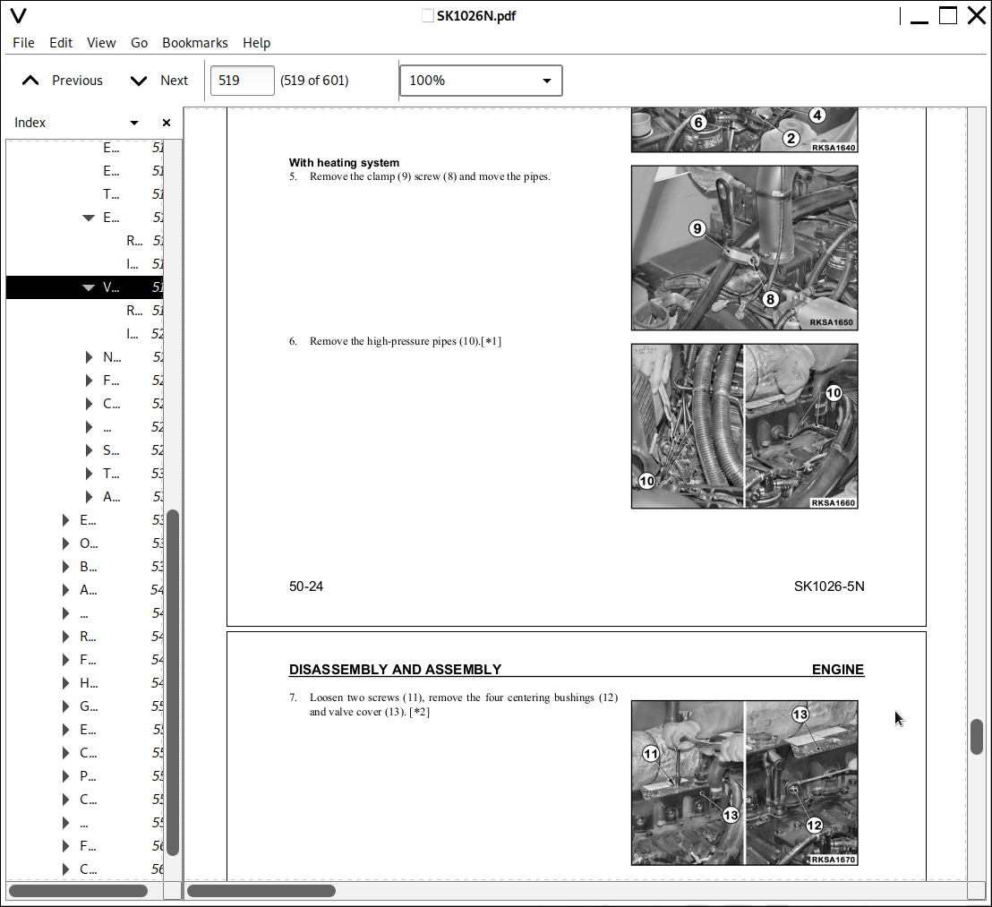
Valve Cover.....519
Removal.....519
Installation.....520
Nozzle Holder.....521
Removal.....521
Installation.....521
Fuel Injection Pump.....522
Removal.....522
Installation.....524
Cylinder Head.....525
Removal.....525
Installation.....527
Water Pump.....528
Removal.....528
Installation.....528
Starter Motor.....529
Removal.....529
Installation.....529
Turbocharger.....530
Removal.....530
Installation.....530
Alternator.....531
Removal.....531
Installation.....531
ENGINE HOOD ASSEMBLY.....532
Removal.....532
Installation.....532
OPERATORS CAB ASSEMBLY.....533
Tilting the Cab.....533
Lowering the Cab.....535
Removing the Cab Assembly.....536
Installing the Cab.....538
BATTERY.....539
Removal.....539
Installation.....539
AIR CLEANER ASSEMBLY.....540
Removal.....540
Installation.....540
MUFFLER ASSEMBLY.....541
Removal.....541
Installation.....542
RADIATOR ASSEMBLY.....543
Removal.....543
Installation.....544
FUEL TANK ASSEMBLY.....545
Removal.....545
Installation.....546
HYDRAULIC PUMP ASSEMBLY.....547
Removal.....547
Installation.....549
GEAR PUMP ASSEMBLY.....550
Removal.....550
Installation.....550
ENGINE-PUMP COUPLING.....551
Removal.....551
Installation.....551
CONTROL VALVE.....552
Removal.....552
Installation.....552
PPC VALVES.....553
Removal.....553
Installation.....553
CAB HEATER ASSEMBLY.....555
Removal.....555
Installation.....556
WHEEL HUB ASSEMBLY.....557
Removal.....557
Installation.....558
Disassembly.....559
Assembly.....560
FINAL DRIVE ASSEMBLY.....561
Removal.....561
Installation.....562
CYLINDER ASSEMBLIES.....563
Lift Cylinder Assembly.....563
Removal.....563
Installation.....564
Bucket Cylinder Asssembly.....565
Removal.....565
Installation.....566
Disassembly of the Cylinder Assembly.....567
Assembly of the Cylinder Assembly.....569
Assembly of the Cylinder Head.....569
Piston Assembly.....570
Piston Rod Assembly.....570
Cylinder Assembly.....571
WORK EQUIPMENT SYSTEM.....573
Removal of the Complete Work Equipment.....573
Installation of the Complete Work Equipment.....575
Removal of the Fulcrum Lever.....576
Installation of the Fulcrum Lever.....576
Removal of the Lift Lever.....577
Installation of the Lift Lever.....578
Removal of the Work Equipment Support Frame.....579
Installation of the Work Equipment Support Frame.....579
90 DIAGRAMS AND SCHEMATICS.....580
HYDRAULIC SYSTEM.....582
Road Specification.....582
Standard + Pattern Change.....583
Super-Flow + Float + Pattern Change.....584
Standard + Float + Pattern Change.....585
Standard + Float.....586
High-Flow + Float.....587
ELECTRICAL SYSTEM.....588
Engine Line.....588
Frame Line - Standard.....589
Frame Line - Optional.....590
Cab Line - Standard (1 of 2).....591
Cab Line - Standard (2 of 2).....592
Cab Line - Optional (1 of 3).....593
Cab Line - Optional (2 of 3).....594
Cab Line - Optional (3 of 3).....595
Top-Cab Light Line - Standard.....596
Top-Cab Light Line - Optional.....597
Rear Light Line.....598
Standard.....599
Optional (1 of 2).....600
Optional (2 of 2).....601
![]()