
Volvo G736 VHP Motor Graders Repair & Service Manual
Complete repair service manual with electrical wiring diagrams for Volvo G736 VHP Motor Graders, with technical information to maintain, diagnose, repair, and service like professional mechanics.
Volvo G736 VHP Motor Graders workshop service & repair manual includes:
* Numbered table of contents easy to use so that you can find the information you need fast.
* Detailed sub-steps expand on repair procedure information
* Numbered instructions guide you through every repair procedure step by step.
* Troubleshooting and electrical service procedures are combined with detailed wiring diagrams for ease of use.
* Notes, cautions and warnings throughout each chapter pinpoint critical information.
* Bold figure number help you quickly match illustrations with instructions.
* Detailed illustrations, drawings and photos guide you through every procedure.
* Enlarged inset helps you identify and examine parts in detail.
Volvo G736 VHP Motor Graders Repair & Service Manual.pdf
PRODUCT DETAILS: 653 pages
File Format: PDF (Windows & Mac & Linux)
Language: English
TABLE OF CONTENTS
0 - Foreword...2
0 - GENERAL...3
00 - DESCRIPTION; COMPLETE MACHINE...4
Conversion Factors...4
Decimal and metric equivalents...6
English to metric conversion factors...8
03 - SPECIFICATIONS...10
Cylinder cycle time in seconds...10
Senders, switches and coils...12
Standard torque guide...14
1 - STANDARD PARTS, SERVICE...15
Charging batteries...16
Circle adjustment...17
Cleanliness, brake and hydraulic systems...20
Description...21
Electric welding...22
Installing final drive assembly onto grader...23
Lock_unlock function...25
Operation...26
Pinion wear...27
Recommended lubricants...28
Removing final drive assembly from grader...30
Repairing hydraulic system...32
Specifications...33
Tire Pressure Tables...34
Towing...35
Transporting...38
2 - ENGINE WITH MOUNTING AND EQUIPMENT...42
Description...43
Engine Installation...44
Engine Removal...49
General...55
Installing the final drive assembly onto the grader...56
Lock_unlock function...63
Low power complaint troubleshooting guide...64
Lubrication circuit...74
Operation...75
Removing the final drive assembly from the grader...77
Specifications...85
Torque Guide...86
VHP parts not supplied by Cummins...88
Variable Horsepower (VHP)...90
3 - ELECTRICAL; WARNING; INFORMATION; INSTRUMENTS...92
5 amp converter option...94
All Wheel Drive system...95
Auxiliary and EEC lights...96
Beacons and heated mirrors...97
Blade and front float modules...98
Blade float module...99
Brakes and supplemental steering...100
Component specification and identification...101
Converter installation 24V to 12V – 10 amp...103
Converter installation – 75 amp...105
Description-[3331]...107
Differential lock, horn, and back-up circuits...108
Electrical Schematic Legend...109
Engine shutdown systems...112
Flood and dome lights...113
Front float module...114
Fuses, circuit breakers and relays...115
Glossary of Abbreviations...117
Heater and air conditioning...119
Index and symbology...120
Key switch...121
Main lights...122
Main power and ignition...123
Monitoring module (page 1)...124
Monitoring module (page 2)...125
Operation...126
Optional converter systems...127
Radio and tire pump...128
Special instructions for working on the electrical system...129
Table 1 – Wire codes...130
Table 2 – Wire codes (continued)...131
Table 3 – Connectors (numerical)...132
Table 3 – Wire codes (continued)...133
Table 4 – Connectors (alphabetical)...134
Transmission and VHP controls...135
Windshield washers and wipers...136
4 - POWER TRANSMISSION...137
40 - GENERAL...138
Clutch assembly – Removal and installation...138
Description...146
Specifications...149
41 - CLUTCH; TORQUE CONVERTER...151
Clutch slave cylinder and pedal free play...151
Description...153
Specifications...156
42 - TRANSMISSION; HYDRAULIC CONTROL...157
Description...157
Specifications...170
Transmission installation...171
Transmission removal...176
Transmission troubleshooting...180
43 - GEARBOX...194
Description...194
Specifications...215
Troubleshooting...216
44 - HYDROSTATIC DRIVE...234
General...234
45 - PROPELLER SHAFT...235
Specifications...235
Tandem assembly...236
Tandem removal...238
5 - BRAKE...243
50 - GENERAL...244
Overview ...244
51 - WHEEL BRAKE...247
Brake housing pre-assembly...247
Description...249
General...252
Oil disc brake assembly – Removal...253
Oil disc brake installation...264
Oil disc brakes – Assembly...269
Oil disc brakes – Bench adjustment...276
Seal installation Procedure...278
Tandem axle oil seal installation...284
52 - HYDRAULIC BRAKE SYSTEM...286
Adjustment checks...286
Brake master cylinder and power booster...288
Description...297
Specifications...306
55 - PARKING BRAKE...307
Description...307
General ...310
Hand brake and caliper...313
Self-adjusting caliper...329
Specifications ...334
6 - STEERING...335
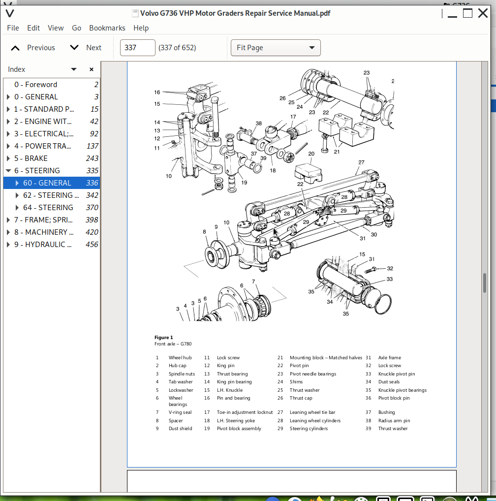
60 - GENERAL...336
Description ...336
Front axle pivot...339
Front axle toe-in...340
Tightening torques...341
62 - STEERING AXLE...342
Axle disassembly and assembly...342
Steering axle – Assembly...355
Steering axle – Disassembly...362
64 - STEERING...370
Components...370
Description ...371
Description-...373
Description...374
Function...376
General description...378
Hydraulic cylinder specifications...379
Specifications-...380
Specifications...381
Steering column disassembly and assembly...382
Steering control unit overhaul procedure...384
7 - FRAME; SPRINGS; DAMPING; AXLE SUSPENSION; WHEEL_TRACK UNIT...398
71 - FRAME...399
Description...399
74 - FRAME LINK...400
Articulation hinge – Assembly...400
Articulation hinge – Disassembly...404
Articulation hinge – Preparation for disassembly...407
Articulation hinge...409
Articulation hydraulics...411
Cleaning and inspection...413
Tightening torques...414
77 - WHEELS; TRACKS; TYRE; HUB; DRUM...415
General description – Wheels...415
Specifications...417
Tire troubleshooting guide...418
8 - MACHINERY HOUSE; CAB; EXTERIOR TRIM PARTS ANYWHERE...420
87 - AIR CONDITIONING UNIT...421
Air conditioner service...421
Air conditioning system repairs...422
Air conditioning system...424
Basic operational checks...425
Cab air distribution...426
Climate control unit electrical schematic...427
Description...429
HVAC routine maintenance...430
HVAC system components...432
Operating principle...437
Specifications...439
Troubleshooting guide...441
88 - INTERIOR EQUIPMENT...444
Description...444
Pedestal disassembly and assembly...449
Pedestal locking strut...454
9 - HYDRAULIC SYSTEM; DIGGING_HANDLING_GRADING EQUIPMENT; MISCELLANEOUS...456
90 - GENERAL...457
Accumulator precharge adjustment chart...457
Auxiliary load sense shuttle valve...458
Blade lift options – Sheet 3...459
Charging the Accumulator...460
Checking the precharge pressure...462
Circle turn valve overhaul procedure...464
Components...476
Description-[3632]...478
Description-[3658]...479
Description-[3724]...480
Description-[3749]...481
Description-[3815]...482
Description-[3841]...483
Description-[3907]...484
Description-[3932]...485
Description-[3958]...486
Double lock valve...487
Flow rates-...488
Flow rates...489
Function-[2719]...490
Function-[2744]...491
Function-[2817]...492
Function...494
General-[2214]...495
General-[2240]...496
General-[2448]...497
General...498
Hydraulic components, location...499
Hydraulic cylinder overhaul procedure...501
Hydraulic swivel joint overhaul procedure...512
Hydraulic system bleeding procedure...521
Hydraulic system pressure tests...522
Hydraulic system troubleshooting guide...523
Load sense module...525
Main control valve overhaul procedure...528
Main control valve section...537
Main control valve spool flow rates...539
Main control valve troubleshooting...540
Main hydraulic circuit...541
Main hydraulic pump overhaul procedure...543
Main hydraulic pump troubleshooting guide...556
Main hydraulic pump, components...557
Main hydraulic schematic - ECC – Sheet 2...559
Main hydraulic schematic – Sheet 1...560
Pictorial torque guide...561
Preventive maintenance...562
Priority flow valve operation...563
Single attachment valve with relief (EEC)...567
Single lock valve...568
Special tools...569
Specific hydraulic circuit problems...570
Specifications-[2749]...572
Specifications-[2815]...574
Specifications-[2841]...576
Specifications-[2907]...577
Specifications-[2933]...578
Specifications-[2959]...579
Specifications-[3025]...580
Specifications-[3050]...581
Specifications-[3123]...582
Specifications-[3156]...584
Specifications-[3222]...586
Specifications-[3247]...587
Specifications-[3313]...588
Specifications-[3339]...590
Specifications-[4136]...591
Specifications-[4202]...592
Specifications-[4227]...593
Specifications-[4253]...594
Specifications-[4319]...595
Specifications-[4345]...596
Specifications-[4418]...597
Specifications-[4450]...599
Specifications-[4523]...601
Specifications-[4549]...602
Specifications-[4615]...603
Specifications-[4641]...605
Specifications-[4706]...606
Specifications-[4758]...607
Steering control unit troubleshooting...608
Steering hydraulic circuit components...611
Steering system troubleshooting guide...613
Supplemental steering circuit – Sheet 4...614
Test procedures-[2008]...616
Test procedures...617
98 - FUNCTION FOR ROAD CONSTRUCTION...618
Circle operation...618
Circle setup and timing...621
Circle turn mechanism, all models...623
Description-...627
Description...629
Drawbar ball stud, all models...632
G710 to G740 Circle and drawbar...634
G780 circle and drawbar...640
MBCS disassembly and assembly...644
Overview...649
Specifications-...650
Specifications...651
Troubleshooting guide...652
Volvo G736 VHP Motor Graders Repair & Service Manual
![]()