
Komatsu Wheeled Excavator PW180-7E0 Repair Service Manual
Complete service repair manual with Electrical Wiring Diagrams for Komatsu Wheeled Excavator PW180-7E0, with all the technical information to maintain, diagnose, repair, rebuild like professional mechanics.
Komatsu Wheeled Excavator PW180-7E0 workshop service repair manual includes:
* Numbered table of contents easy to use so that you can find the information you need fast.
* Detailed sub-steps expand on repair procedure information
* Numbered instructions guide you through every repair procedure step by step.
* Troubleshooting and electrical service procedures are combined with detailed wiring diagrams for ease of use.
* Notes, cautions and warnings throughout each chapter pinpoint critical information.
* Bold figure number help you quickly match illustrations with instructions.
* Detailed illustrations, drawings and photos guide you through every procedure.
* Enlarged inset helps you identify and examine parts in detail.
PRODUCT DETAILS:
Total Pages: 1,415 pages
File Format: PDF (Internal Links, Bookmarked, Table of Contents, Searchable, Printable, high quality)
Language: English
UEAM004501 - Wheeled Excavator PW180-7K Operation & Maintenance Manual.pdf
VEBM400100 - Wheeled Excavator PW180-7E0 Shop Manual.pdf
MAIN SECTIONS
UEAM004501 - Wheeled Excavator PW180-7K Operation & Maintenance Manual.....2
FOREWORD.....4
FOREWORD.....5
SAFETY INFORMATION.....6
SAFETY MESSAGES.....6
Noise emission levels.....7
Vibration levels.....7
Guide to Reduce Vibration Levels on Machine.....8
EMERGENCY STEERING.....10
EMERGENCY BRAKING.....10
INTRODUCTION.....11
INTENDED USE.....11
FEATURES.....11
BREAKING IN YOUR NEW MACHINE.....12
LOCATIONS OF PLATES, TABLE TO ENTER SERIAL NO. AND DISTRIBUTOR.....13
MACHINE SERIAL NO. PLATE POSITION.....13
ENGINE SERIAL NO. PLATE POSITION.....13
TABLE TO ENTER SERIAL NO. AND DISTRIBUTOR.....13
MACHINE SERIAL PLATES.....14
STANDARD SERIAL PLATE.....14
GERMANY SERIAL PLATE.....14
ITALIAN SERIAL PLATE.....14
SAFETY.....22
GENERAL PRECAUTIONS.....23
PRECAUTION DURING OPERATION.....30
BEFORE STARTING ENGINE.....30
OPERATING MACHINE.....31
TRANSPORTATION.....38
BATTERY.....39
BATTERY HAZARD PREVENTION.....39
TOWING.....40
BUCKET WITH HOOK OR BUCKET LINK WITH LIFTING EYE.....41
GENERAL PRECAUTIONS.....41
PRECAUTIONS FOR LIFTING OPERATION.....43
HANDLING OF FLUIDS.....45
PRECAUTIONS FOR MAINTENANCE.....46
BEFORE CARRYING OUT MAINTENANCE.....46
DURING MAINTENANCE.....49
POSITION FOR ATTACHING SAFETY LABELS.....52
POSITION FOR ATTACHING SAFETY LABELS.....52
LIFTING CAPACITY CHART PW180-7K.....60
ONE PIECE BOOM Lift capacity tables for 2.5 metre undercarriage.....60
ONE PIECE BOOM Lift capacity tables for 2.75 metre undercarriage.....66
TWO PIECE BOOM Lift capacity tables for 2.5 metre undercarriage.....72
TWO PIECE BOOM Lift capacity tables for 2.75 metre undercarriage.....78
OVERLOAD CAUTION.....84
Monoboom Overload Caution.....84
2 Piece Boom Overload Caution.....85
OPERATION.....86
GENERAL VIEW.....87
GENERAL VIEW OF MACHINE.....87
GENERAL VIEW OF CONTROLS AND GAUGES.....88
EXPLANATION OF COMPONENTS.....89
MACHINE MONITOR.....89
BASIC OPERATION OF MACHINE MONITOR.....90
BASIC CHECK ITEMS.....92
CAUTION ITEMS.....94
EMERGENCY STOP ITEMS.....98
METER DISPLAY PORTION.....101
METERS.....103
MONITOR SWITCHES.....107
SWITCHES.....120
CONTROL LEVERS, PEDALS.....128
FRONT WINDOW.....133
EMERGENCY EXIT FROM OPERATOR'S CAB.....137
CAP, COVER WITH LOCK.....139
METHOD OF OPENING AND CLOSING CAP WITH LOCK (For the fuel tank filler port).....139
METHOD OF OPENING AND CLOSING COVER WITH LOCK (cover with lock).....139
FUSE.....140
LUGGAGE TRAY.....141
ASHTRAY.....141
CUP HOLDER.....141
HOT AND COOL BOX.....141
CAB RADIO.....142
PRECAUTION OF USE.....142
POWER PICK-UP PORT.....142
HANDLING AIR CONDITIONER.....143
GENERAL LOCATIONS OF CONTROL PANEL.....143
METHOD OF OPERATION.....147
PRECAUTIONS WHEN USING AIR CONDITIONER.....153
CHECK, MAINTAIN MACHINE EQUIPPED WITH AIR CONDITIONER.....153
OTHER FUNCTIONS.....153
FUSIBLE LINK.....155
CONTROLLER.....155
TOOL BOX (CHASSIS).....155
REFUELLING PUMP.....156
SAFETY.....156
PROCEDURE.....156
MAINTENANCE.....157
WARNING LAMPS.....158
HANDLING ACCUMULATORS.....159
OPERATION.....161
CHECK BEFORE STARTING ENGINE.....161
WALK-AROUND CHECK.....161
CHECK BEFORE STARTING.....163
ADJUSTMENT OF OPERATORS SEAT (AIR SUSPENSION SEAT).....168
SEAT BELT.....170
ADJUSTMENT OF OPERATORS SEAT (MECHANICAL SEAT).....170
SEAT BELT.....171
OPERATIONS AND CHECKS BEFORE STARTING ENGINE.....172
STARTING ENGINE.....174
NORMAL STARTING.....174
STARTING IN COLD WEATHER.....175
OPERATIONS AND CHECKS AFTER STARTING ENGINE.....177
WARMING UP OPERATION.....177
IN COLD AREAS (AUTOMATIC WARMING-UP OPERATION).....180
MOVING MACHINE OFF.....183
MOVING MACHINE FORWARD.....183
STEERING.....186
TRAVELLING ON PUBLIC HIGHWAY.....187
STOPPING & PARKING.....188
STOPPING MACHINE (EMERGENCY).....189
SWINGING (Slewing the upper carriage).....190
OPERATION OF WORK EQUIPMENT.....191
WORKING MODE SELECTION.....193
PROHIBITIONS FOR OPERATION.....195
PRECAUTIONS FOR OPERATION.....196
RECOMMENDATIONS FOR TRAVELLING.....198
PRECAUTIONS WHEN TRAVELLING UP OR DOWN HILLS.....199
HOW TO ESCAPE FROM MUD.....200
WHEN ONE SIDE IS STUCK.....200
WHEN BOTH SIDES ARE STUCK.....200
WORK POSSIBLE USING HYDRAULIC EXCAVATOR.....201
BACKHOE WORK.....201
SHOVEL WORK.....201
DITCHING WORK.....201
LOADING WORK.....202
LEVELLING WORK.....202
REPLACEMENT AND INVERSION OF BUCKET.....202
REPLACEMENT.....202
INVERSION.....203
STOPPING ENGINE.....204
CHECK AFTER FINISHING WORK.....204
CHECK AFTER STOPPING ENGINE.....205
LOCKING.....205
HANDLING THE WHEELS.....205
TRANSPORTATION.....210
LOADING, UNLOADING WORK.....210
PRECAUTIONS FOR LOADING.....212
HOW TO LIFT THE MACHINE.....213
PRECAUTIONS FOR TRANSPORTATION.....215
TRAVELLING POSTURE.....217
COLD WEATHER OPERATION.....219
PRECAUTIONS FOR LOW TEMPERATURE.....219
FUEL AND LUBRICANTS.....219
BATTERY.....220
PRECAUTIONS AFTER COMPLETION OF WORK.....221
AFTER COLD WEATHER.....221
LONG-TERM STORAGE.....222
BEFORE STORAGE.....222
DURING STORAGE.....222
AFTER STORAGE.....223
STARTING MACHINE AFTER LONG-TERM STORAGE.....223
TROUBLESHOOTING.....224
PHENOMENA THAT ARE NOT FAILURES.....224
METHOD OF TOWING MACHINE.....225
PRECAUTIONS ON PARTICULAR JOBSITES.....225
DISCHARGED BATTERY.....226
REMOVAL AND INSTALLATION OF BATTERY.....226
BATTERY CHARGES.....227
STARTING ENGINE WITH BOOSTER CABLES.....228
OTHER TROUBLE.....230
ELECTRICAL SYSTEM.....230
CHASSIS.....231
ENGINE.....232
ELECTRONIC CONTROL SYSTEM.....234
MAINTENANCE.....236
GUIDES TO MAINTENANCE.....237
OUTLINE OF SERVICE.....240
OUTLINE OF OIL, FUEL, COOLANT.....240
OIL.....240
FUEL.....241
COOLANT.....241
GREASE.....242
CARRYING OUT KOWA (Komatsu Oil Wear Analysis).....242
STORING OIL AND FUEL.....243
FILTERS.....243
OUTLINE OF ELECTRIC SYSTEM.....244
OUTLINE OF HYDRAULIC SYSTEM.....245
WEAR PARTS LIST.....246
USE FUEL, COOLANT AND LUBRICANTS ACCORDING TO AMBIENT TEMPERATURE.....247
PROPER SELECTION OF FUEL, COOLANT AND LUBRICANTS.....247
USE FUEL, COOLANT AND LUBRICANTS ACCORDING TO AMBIENT TEMPERATURE CONT.....249
STANDARD TIGHTENING TORQUES FOR BOLTS AND NUTS.....251
INTRODUCTION OF NECESSARY TOOLS.....251
TIGHTENING TORQUE SPECIFICATIONS.....252
TIGHTENING TORQUE LIST.....252
PERIODIC REPLACEMENT OF SAFETY CRITICAL PARTS.....253
SAFETY CRITICAL PARTS.....254
MAINTENANCE SCHEDULE CHART.....255
KEY TO LUBRICATION POINTS.....259
SERVICE PROCEDURE.....261
INITIAL 250 HOURS SERVICE.....261
WHEN REQUIRED.....262
CHECK, CLEAN AND REPLACE AIR CLEANER ELEMENT.....262
CLEAN INSIDE OF COOLING SYSTEM.....267
CLEAN INSIDE OF COOLING SYSTEM.....268
CHECKING COOLANT LEVEL.....270
DRAINING THE SYSTEM.....270
CLEANING THE SYSTEM.....271
FILLING THE SYSTEM.....271
REFILLING AN OVERHEATED SYSTEM.....271
CLEANING THE RADIATOR.....272
THERMOSTAT.....272
FAN.....273
CHECK AND TIGHTEN WHEEL NUTS.....273
CHECK ELECTRICAL INTAKE AIR HEATER.....273
CHECK ALTERNATOR.....273
CHECK START MOTOR.....274
REPLACE BUCKET SIDE CUTTERS.....274
REPLACE BUCKET TEETH.....276
REPLACE BUCKET TEETH (VERTICAL PIN TYPE).....276
REPLACE BUCKET TEETH (HORIZONTAL PIN TYPE).....279
ADJUST BUCKET CLEARANCE.....280
CHECK WINDOW WASHER FLUID LEVEL, ADD FLUID.....281
CHECK AND ADJUST AIR CONDITIONER.....282
CHECK LEVEL OF REFRIGERANT (GAS).....282
DRAIN ENGINE BREATHER OIL CATCHER.....283
CHECK BEFORE STARTING.....283
CHECK COOLANT LEVEL, ADD WATER.....283
CHECK OIL LEVEL IN ENGINE OIL PAN, ADD OIL.....284
CHECK FUEL LEVEL, ADD FUEL.....285
CHECK OIL LEVEL IN HYDRAULIC TANK, ADD OIL.....286
CHECK AIR CLEANER FOR CLOGGING.....286
CHECK ELECTRIC WIRING.....287
CHECK FOR WATER AND SEDIMENT IN SEDIMENTOR. DRAIN WATER AND SEDIMENT.....287
EVERY 50 HOURS.....288
DRAIN WATER AND SEDIMENT FROM FUEL TANK.....288
EVERY 100 HOURS SERVICE.....288
LUBRICATING.....288
CLEANING FRESH AIR FILTER.....293
EVERY 250 HOURS MAINTENANCE.....294
CHECK OIL LEVEL IN MACHINERY CASE, ADD OIL.....294
CHECK OIL LEVEL IN WHEEL HUBS, ADD OIL (Front Axle).....295
CHECK OIL LEVEL IN WHEEL HUBS, ADD OIL (Rear Axle).....295
CHECK OIL LEVEL IN AXLES, ADD OIL.....295
CHECK OIL LEVEL IN TRANSMISSION, ADD OIL.....296
CHECK LEVEL OF BATTERY ELECTROLYTE.....296
BELTS, GENERAL.....297
CHECK FAN BELT TENSION, ADJUST TENSION.....297
CHECK, ADJUST TENSION OF AIR CONDITIONER COMPRESSOR BELT.....298
EVERY 500 HOURS SERVICE.....300
LUBRICATE SWING CIRCLE (2 POINTS).....300
REPLACE FUEL FILTER CARTRIDGE.....301
CHECK SWING PINION GREASE LEVEL, ADD GREASE.....302
CHANGE OIL IN ENGINE OIL PAN, REPLACE ENGINE OIL FILTER CARTRIDGE.....303
CLEAN AND INSPECT RADIATOR FINS, OIL COOLER FINS AND CONDENSER FINS.....304
CLEAN INTERNAL AND EXTERNAL AIR FILTERS OF AIR CONDITIONER SYSTEM.....305
CLEANING RECIRCULATED AIR FILTER.....306
REPLACE HYDRAULIC TANK BREATHER ELEMENT.....307
CHECK CONDITION OF MAIN VALVE RUBBER MOUNTS.....307
EVERY 1000 HOURS SERVICE.....308
REPLACE HYDRAULIC FILTER ELEMENT.....308
CHANGE OIL IN SWING MACHINERY CASE.....309
CHECK ALL TIGHTENING PARTS OF TURBOCHARGER.....310
CHECK PLAY OF TURBOCHARGER ROTOR.....310
CHECK & ADJUST VALVE CLEARANCE.....310
CHECK FAN BELT TENSIONER BEARING BELT AND FAN HUB.....310
CHECK FAN BELT TENSION AND REPLACE FAN BELT.....310
CHANGE OIL IN AXLES.....311
CHANGE OIL IN HUBS.....312
CHANGE OIL IN TRANSMISSION ASSEMBLY.....313
EVERY 2000 HOURS SERVICE.....314
CLEAN HYDRAULIC TANK STRAINER.....314
CLEANING THE STRAINER OF THE BRAKE FILTER.....315
CLEAN, CHECK TURBOCHARGER.....315
CHECK ALTERNATOR, STARTING MOTOR.....315
CHANGE ANTIFREEZE.....315
CHECK AND ADJUST VALVE CLEARANCE.....316
EVERY 4000 HOURS SERVICE.....316
CHECK WATER PUMP.....316
EVERY 5000 HOURS SERVICE.....317
CHANGE OIL IN HYDRAULIC TANK AND REPLACE STEER/BRAKE CIRCUIT STRAINER.....317
PROCEDURE FOR BLEEDING AIR.....319
SPECIFICATIONS.....320
SPECIFICATIONS.....321
1 - PIECE BOOM.....323
2 - PIECE BOOM.....325
WORKING RANGE: ONE PIECE BOOM.....327
WORKING RANGE: TWO PIECE BOOM.....328
OPTIONS, ATTACHMENTS.....330
GENERAL PRECAUTIONS.....331
PRECAUTIONS RELATED TO SAFETY.....331
PRECAUTIONS WHEN INSTALLING ATTACHMENTS.....332
HANDLING BUCKET WITH HOOK.....334
CHECKING FOR DAMAGE TO BUCKET WITH HOOK.....334
PROHIBITED OPERATIONS.....334
PRECAUTIONS DURING OPERATIONS.....334
MACHINES READY FOR ATTACHMENTS.....335
HANDLING THE CLAMSHELL BUCKET.....337
How to install clamshell bucket.....337
HOW TO OPERATE.....337
HYDRAULIC CIRCUIT.....339
SWITCHING HYDRAULIC CIRCUIT.....339
OPERATION.....340
WHEN USING CRUSHER OR OTHER GENERAL ATTACHMENT.....341
WHEN USING BREAKER.....342
METHOD FOR RELEASING PRESSURE IN CONTROL CIRCUIT OF MACHINES EQUIPPED WITH ACCUMULATOR.....343
LONG-TERM STORAGE.....343
SPECIFICATIONS.....343
INTRODUCTION OF ATTACHMENTS AND EXTENDING MACHINE SERVICE LIFE.....344
HYDRAULIC BREAKER.....344
POWER RIPPER.....347
FORK GRAB.....348
GRAPPLE BUCKET.....349
SCRAP GRAPPLE.....350
CRUSHER & SMASHER.....352
HYDRAULIC PILE DRIVER.....353
HYDRAULIC EXCAVATOR WITH MULTIPURPOSE CRANE.....354
GENERAL VIEW OF CONTROLS.....356
LEFT CONTROL LEVER (with auto-deceleration device).....357
RIGHT CONTROL LEVER (with auto-deceleration device).....357
UPPER BOOM CONTROL PEDAL (2 PIECE BOOM).....358
EXCAVATORS WORK.....358
REPLACEMENT OF BUCKET.....360
HANDLING THE TRAPEZOIDAL BUCKET (If equipped).....361
VEBM400100 - Wheeled Excavator PW180-7E0 Shop Manual.....368
VEBM400100 PW180-E0.....368
SAFETY.....370
SAFETY NOTICE.....370
01 GENERAL.....378
SPECIFICATION DIMENSION DRAWINGS.....395
DIMENSIONS.....395
WORKING RANGES.....399
1 PIECE BOOM.....399
2 PIECE BOOM.....400
SPECIFICATIONS.....401
FUEL, COOLANT AND LUBRICANTS.....406
WEIGHT TABLE.....403
1 PIECE BOOM.....404
2 PIECE BOOM.....405
HOISTING INSTRUCTIONS.....380
HOW TO READ THE SHOP MANUAL.....379
COATING MATERIALS.....381
STANDARD TIGHTENING TORQUE.....383
STANDARD TIGHTENING TORQUE OF BOLTS AND NUTS.....383
TIGHTENING TORQUE OF HOSE NUTS.....384
TIGHTENING TORQUE OF SPLIT FLANGE BOLTS.....384
TIGHTENING TORQUES FOR HOSES (Taper seal type and face seal type).....384
TIGHTENING TORQUE FOR 107 ENGINE SERIES (BOLTS AND NUTS).....385
TIGHTENING TORQUE FOR 107 ENGINE SERIES (EYE JOINTS).....385
TIGHTENING TORQUE FOR 107 ENGINE SERIES (TAPERED SCREWS).....385
ELECTRIC WIRE CODE.....386
CLASSIFICATION BY THICKNESS.....386
CLASSIFICATION BY COLOR AND CODE.....386
CONVERSION TABLES.....387
METHOD OF USING THE CONVERSION TABLE.....387
UNITS.....393
DIMENSIONS.....397
2 PIECE BOOM.....397
10 STRUCTURE, FUNCTION AND MAINTENANCE .....408
ENGINE RELATED PARTS.....409
RADIATOR . OIL COOLER . CHARGE AIR COOLER.....410
POWER TRAIN.....411
SWING CIRCLE.....413
SWING MACHINERY & MOTOR.....414
SWING MOTOR.....417
Operation of swing lock.....421
RELIEF VALVE PORTION.....422
UNDERCARRIAGE.....423
TRANSMISSION.....425
TRAVEL MOTOR.....429
OPERATION OF TRAVEL MOTOR.....431
CLUTCH CONTROL CIRCUIT.....433
AXLE.....435
SUSPENSION LOCK CYLINDER.....439
BRAKING SYSTEM.....441
BRAKE/STEER PUMP.....443
PRIORITY VALVE.....444
POWER BRAKE VALVE.....445
ACCUMULATOR FOR BRAKE VALVE.....447
STEERING SYSTEM.....448
STEERING COLUMN.....449
ORBITROL VALVE.....450
HYDRAULIC EQUIPMENT LAYOUT DRAWINGS.....451
HYDRAULIC CIRCUIT DIAGRAM.....453
HYDRAULIC TANK.....454
HYDRAULIC PUMP.....456
LS VALVE.....461
PC VALVE.....462
LS(PC)-EPC VALVE.....476
PILOT PRESSURE CONTROL (PPC) SYSTEM.....480
CONTROL VALVE.....482
PW180-7E0.....482
CLSS.....493
OUTLINE OF CLSS.....493
BASIC PRINCIPLE.....494
OPERATION FOR EACH FUNCTION AND VALVE.....496
1. Unload valve.....498
2. Introduction of LS pressure.....501
3. LS Bypass plug.....502
4. Pressure compensation valve.....504
5. Area ratio of pressure compensation valve.....506
6. Boom regeneration circuit.....508
7. Arm regeneration circuit.....510
8. Swing bleeding valve.....512
9. Variable type pressure compensation valve (for service).....513
10. LS select valve.....514
CENTRE SWIVEL JOINT.....515
TRAVEL PPC PEDAL.....516
WORK EQUIPMENT . SWING PPC VALVE.....518
SOLENOID VALVE BLOCK.....524
SOLENOID VALVE BLOCK.....526
BOOM SAFETY VALVE.....533
HYDRAULIC CYLINDER.....535
OUTRIGGER CYLINDER.....537
DOZER CYLINDER.....539
WORK EQUIPMENT.....541
Work Equipment.....542
1. DIMENSION OF ARM.....543
AIR CONDITIONER.....547
AIR CONDITIONER PIPING.....547
ELECTRICAL WIRING DIAGRAM.....548
ELECTRICAL SYSTEM.....549
ELECTRONIC CONTROL SYSTEM.....555
MACHINE CONTROL SYSTEM DIAGRAM.....556
MACHINE MONITOR SYSTEM.....580
OVERLOAD WARNING DEVICE.....608
OUTLINE.....608
SENSOR.....609
1st ATTACHMENT CIRCUIT HYDRAULIC PERFORMANCE (MAIN VALVE BYPASSED).....618
TRAVEL SYSTEM.....619
TRAVEL CIRCUIT.....619
OPERATIONAL AND CONTROL FEATURES.....620
STEERING SYSTEM.....638
OPERATING PRINCIPLES.....638
SERVICE BRAKE AND SUSPENSION SYSTEM.....651
BRAKING SYSTEM.....651
OPERATION.....654
20 TESTING AND ADJUSTING.....656
STANDARD VALUE TABLE FOR ENGINE RELATED PARTS.....657
STANDARD VALUE TABLE FOR CHASSIS RELATED PARTS.....658
Flow control characteristic of PC valve (STD).....670
MEASURING ENGINE SPEED.....673
MEASURING INTAKE AIR PRESSURE (BOOST PRESSURE).....674
MEASUREMENT OF EXHAUST GAS COLOUR.....675
ADJUSTING VALVE CLEARANCE.....677
MEASURING COMPRESSION PRESSURE.....679
MEASURING BLOW-BY PRESSURE.....681
MEASURING ENGINE OIL PRESSURE.....682
HANDLING FUEL SYSTEM PARTS.....683
RELEASING RESIDUAL PRESSURE FROM FUEL SYSTEM.....684
MEASURING FUEL PRESSURE.....685
MEASURING FUEL RETURN RATE AND LEAKAGE.....687
BLEEDING AIR FROM FUEL CIRCUIT.....689
Checking fuel circuit for leakage.....691
CHECKING AND ADJUSTING AIR CONDITIONER COMPRESSOR BELT TENSION.....692
MEASUREMENT OF CLEARANCE IN SWING CIRCLE BEARINGS.....693
INSPECTION AND ADJUSTMENT OF HYDRAULIC OIL PRESSURE IN HYDRAULIC CIRCUIT FOR WORK EQUIPMENT, SWING AND TRAVEL.....694
INSPECTION AND ADJUSTMENT OF CONTROL CIRCUIT OIL PRESSURE.....697
INSPECTION AND ADJUSTMENT OF PUMP PC (VALVE INLET) CONTROL OIL PRESSURE.....699
INSPECTION AND ADJUSTMENT OF PUMP LS VALVE CONTROL OIL PRESSURE.....702
MEASUREMENT OF SOLENOID VALVE OUTPUT PRESSURE.....706
Solenoid valve block.....708
MEASUREMENT OF PPC VALVE OUTPUT PRESSURE.....711
ADJUSTMENT OF WORK EQUIPMENT AND SWING PPC VALVE.....713
TESTING TRAVEL MOTOR RELIEF PRESSURE.....714
ADJUSTING TRAVEL MOTOR RELIEF PRESSURE.....715
TESTING PROPSHAFT SPEED.....716
TESTING TRANSMISSION CLUTCH CONTROL CIRCUIT.....717
INSPECTION OF LOCATIONS OF HYDRAULIC DRIFT OF WORK EQUIPMENT.....719
RELEASE OF REMAINING PRESSURE IN HYDRAULIC CIRCUIT.....721
MEASUREMENT OF OIL LEAKAGE.....722
AIR BLEEDING OF VARIOUS PARTS.....725
INSPECTION PROCEDURES FOR DIODE.....728
SPECIAL FUNCTION OF MONITOR PANEL.....730
OPERATION OF OPERATORS MENU AND DISPLAY (OUTLINE).....732
TABLE FOR FAILURE CODE NO.....739
OPERATION AND DISPLAY OF SERVICE MENU.....742
Way of switching to Service Menu.....742
Table for Monitoring Items.....745
PREPARATIONS FOR TROUBLESHOOTING ELECTRICAL SYSTEM.....762
POINTS TO REMEMBER WHEN TROUBLESHOOTING.....765
SEQUENCE OF EVENTS IN TROUBLESHOOTING.....766
POINTS TO REMEMBER WHEN CARRYING OUT MAINTENANCE.....767
CLASSIFICATION AND STEPS FOR TROUBLESHOOTING.....777
Classification of troubleshooting.....777
Steps for troubleshooting.....777
Failure-looking Phenomenon and Troubleshooting No.....778
How to read electric wire code.....781
CONNECTOR LOCATION CHART AND ELECTRICAL CIRCUIT DIAGRAM BY SYSTEM.....784
CONNECTOR LOCATIONS.....791
CONNECTION TABLE FOR CONNECTOR PIN NUMBERS.....813
T-boxes and T-adapters table.....841
Before carrying out troubleshooting when failure code is displayed.....848
INFORMATION CONTAINED IN TROUBLESHOOTING TABLE.....849
Relative Electrical Circuit Diagram.....850
Failure Code [6B2JMA] (Abnormality in travel PPC switch hydraulics).....851
Failure code [989L00] Engine Controller Lock Caution 1.....852
Failure code [989M00] Engine Controller Lock Caution 2.....852
Failure code [989N00] Engine Controller Lock Caution 3.....853
Failure code [AA10NX] Air Cleaner Clogging.....853
Failure code [AB00KE] Charge Voltage Low.....854
Failure code [B@BAZG] Eng Oil Press. Low.....855
Failure code [B@BAZK] Eng Oil Level Low.....855
Failure code [B@BCNS] Eng Water Overheat.....856
Failure code [B@BCZK] Eng Water Level Low.....856
Failure code [B@HANS] Hydr Oil Overheat.....857
Failure code [CA111] EMC Critical Internal Failure.....857
Failure code [CA115] Engine Neutral and Backup Speed Sensor Error.....858
Failure code [CA122] Chg Air Press Sensor High Error.....859
Failure code [CA123] Chg Air Press Sensor Low Error.....861
Failure code [CA131] Throttle Sensor High Error.....863
Failure code [CA132] Throttle Sensor Low Error.....865
Failure code [CA144] Coolant Temp Sens High Error.....867
Failure code [CA145] Coolant Temp Sens Low Error.....869
Failure code [CA153] Chg Air Temp Sensor High Error.....871
Failure code [CA154] Chg Air Temp Sensor Low Error.....873
Failure code [CA155] Chg Air Temp High Speed Derate.....875
Failure code [CA187] Sens Supply 2 Volt Low Error.....877
Failure code [CA221] Ambient Press Sens High Error.....879
Failure code [CA222] Ambient Press Sens Low Error.....881
Failure code [CA227] Sens Supply 2 Volt High Error.....883
Failure code [CA234] Eng Overspeed.....884
Failure code [CA238] Ne Speed Sens Supply Volt Error.....885
Failure code [CA271] IMV/PCV1 Short Error.....886
Failure code [CA272] IMV/PCV1 Open Error.....887
Failure code [CA322] Inj #1 (L#1) Open/Short Error.....889
Failure code [CA323] Inj #5 (L#5) Open/Short Error.....891
Failure code [CA324] Inj #3 (L#3) Open/Short Error.....893
Failure code [CA325] Inj #6 (L#6) Open/Short Error.....895
Failure code [CA331] Inj #2 (L#2) Open/Short Error.....897
Failure code [CA332] Inj #4 (L#4) Open/Short Error.....899
Failure code [CA342] Calibration Code Incompatibility.....901
Failure code [CA351] Injectors Drive Circuit Error.....903
Failure code [CA352] Sens Supply 1 Volt Low Error.....905
Failure code [CA386] Sens Supply 1 Volt High Error.....907
Failure code [CA428] Water in Fuel Sensor High Error.....909
Failure code [CA429] Water in Fuel Sensor Low Error.....911
Failure code [CA435] Eng Oil Press Sw Error.....913
Failure code [CA441] Battery Voltage Low Error.....914
Failure code [CA442] Battery Voltage High Error.....917
Failure code [CA449] Rail Press Very High Error.....919
Failure code [CA451] Rail Press Sensor High Error.....921
Failure code [CA452] Rail Press Sensor Low Error.....923
Failure code [CA488] Chg Air Temp High Torque Derate.....925
Failure code [CA553] Rail Press High Error.....925
Failure code [CA559] Rail Press Low Error.....926
Failure code [CA689] Eng Ne Speed Sensor Error.....929
Failure code [CA731] Eng Bkup Speed Sens Phase Error.....931
Failure code [CA757] All Continuous Data Lost Error.....933
Failure code [CA778] Eng G Speed Sensor Error.....935
Failure code [CA1633] KOMNET Datalink Timeout Error.....937
Failure code [CA2185] Throttle Sensor Supply Voltage High Error.....939
Failure code [CA2186] Throttle Sensor Supply Voltage Low Error.....940
Failure code [CA2249] Rail Press Very Low Error.....941
Failure code [CA2311] IMV Solenoid Error.....943
Failure code [CA2555] Grid Htr Relay Volt High Error.....945
Failure code [CA2556] Grid Heater Relay Volt Low Error.....947
Failure Code [D110KB] (Short-circuiting in battery relay).....949
Failure code [D19JKZ] Personal Code Relay Abnormality.....951
Failure code [DA25KP] Press. Sensor Power Abnormality.....953
Failure code [DA2RMC] Pump Comm. Abnormality.....955
Failure Code [DA2SKQ] (Abnormality in inputting model code).....957
Failure Code [DA2SKQ] (Abnormality in inputting model code).....959
Failure code [DAFRMC] Monitor Comm. Abnormality.....961
Failure Code [DDHPAKP] (Abnormality in pump pressure sensor).....963
Failure Code [DDP4KX] (Abnormality in travel PPC pressure switch).....965
Failure Code [DDWCKZ] (Abnormality in travel direction control switch).....966
Electrical Circuit Diagram for Travel PPC Switch.....966
Failure Code [DH1OKS] (Abnormality in Pressure sensor power source).....967
Failure code [DHPAMA] F Pump Press Sensor Abnormality.....969
Failure Code [DHS5KX] (Abnormality in travel PPC sensor).....971
Failure Code [DHX1MA] (Abnormality in overload caution sensor).....973
Failure Code [DLT4KA] (Disconnection in transmission speed sensor in pump controller system).....975
Failure Code [DW27KA] (Disconnection in Transmission Clutch solenoid).....977
Failure Code [DW27KB] (Short-circuiting in Transmission Clutch solenoid).....979
Failure Code DW4AKA (Disconnection in suspension lock solenoid).....981
Failure Code [DW4AKB] (Short circuiting in suspension lock solenoid).....983
Failure Code [DW4CKA] (Disconnection in PPC lock solenoid).....985
Failure code [DW4CKB] PPC Lock Sol. S/C.....987
Failure Code [DW4MKA] (Disconnection in Creep solenoid).....989
Electrical Circuit Diagram for Creep Solenoid in Pump Controller.....990
Failure Code [DW4MKB] (Short-circuiting in Creep solenoid).....991
Electrical Circuit Diagram for Creep Solenoid in Pump Controller.....992
Failure Code [DW44KA] (Disconnection of Travel F/R solenoid).....993
Failure Code [DW44KB] (Short-circuiting of Travel F/R solenoid).....995
Failure Code [DW45KA] (Disconnection in Swing Parking Brake solenoid).....997
Failure code [DW45KB] Swing Brake Sol. S/C.....999
Failure Code [DW91KA] (Disconnection in Travel Neutral solenoid).....1001
Failure Code [DW91KB] (Short-circuiting in Travel Neutral Solenoid).....1003
Failure Code [DWK0KB] (Short-circuiting in 2-Stage Relief Solenoid).....1007
Failure Code [DWK2KA] (Disconnection in 2-stage Back Pressure solenoid).....1009
Failure Code [DWK2KB] (Short circuiting in 2-stage back pressure solenoid).....1011
Failure Code [DXA0KA] (Disconnection in PC-EPC solenoid system).....1013
Failure Code [DXA0KB] (Short-circuiting in PC-EPC solenoid).....1015
Failure Code [DXE0KA] (Disconnection in LS-EPC solenoid system).....1017
Failure Code [DXE0KB] (Short-circuiting in LS-EPC solenoid).....1018
Failure Code [DXE4KA] (Disconnection in attachment oil flow rate adjusting EPC).....1019
1st Service EPC Solenoid (Left Hand).....1019
1st Service EPC Solenoid (Right Hand).....1020
2nd Service EPC Solenoid (Left Hand).....1021
2nd Service EPC Solenoid (Right Hand).....1022
Failure Code [DXE4KB] (Short-circuiting in attachment oil flow rate adjusting EPC).....1024
1st Service EPC Solenoid (Left Hand).....1024
1st Service EPC Solenoid (Right Hand).....1025
2nd Service EPC Solenoid (Left Hand).....1026
2nd Service EPC Solenoid (Right Hand).....1027
Failure code [DY20KA] Wiper Working Abnormality.....1029
Failure code [DY20MA] Wiper Parking Abnormality.....1031
Failure code [DY2CKB] Washer Drive S/C.....1033
Failure code [DY2DKB] Wiper Drive (For) S/C.....1035
Failure code [DY2EKB] Wiper Drive (Rev) S/C.....1037
INFORMATION CONTAINED IN TROUBLESHOOTING TABLE.....1041
Relative Electrical Circuit Diagram.....1042
E-1 Engine does not start (Engine does not rotate).....1043
Electrical Circuit Diagram for Engine Start, Stop and Battery Charging.....1046
E-5 Auto-decelerator does not work.....1047
E-6 Auto engine warm-up device does not work.....1049
E-7 Preheater does not operate.....1051
E-8 All work equipment, swing and travel do not move.....1053
Electrical Circuit Diagram for PPC Lock Solenoid.....1054
E-9 One-touch Power Max Switch does not work.....1055
Electric Circuit Diagram for One-Touch Power Max. Switch.....1055
E-10 No display in monitor panel at all.....1056
Electrical Circuit Diagram for Power Source in Monitor Panel.....1056
E-11 Part of display on monitor panel is missing.....1057
E-12 Monitor panel displays contents irrelevant to the model.....1057
E-13 Fuel level monitor red lamp lights up while engine is running.....1058
Electrical Circuit Diagram for Fuel Level Sensor.....1058
E14 Engine coolant temperature gauge does not indicate normally.....1059
E-15 Hydraulic oil temperature gauge does not display correctly.....1061
Electrical Circuit Diagram for Hydraulic Oil Temperature Sensor.....1061
E-16 Fuel gauge does not display correctly.....1062
Electrical Circuit Diagram for Fuel Level Sensor.....1062
E-17 Swing lock monitor does not display correctly.....1063
Electrical Circuit Diagram for Swing Lock Switch.....1064
E-18 When the monitor switch is operated, no display appears.....1065
E-19 Windshield wiper and window washer do not operate.....1067
E-20 Alarm buzzer cannot be stopped.....1069
E-21 "Boom/Stabiliser RAISE" is not correctly displayed in monitor function.....1071
Electrical Circuit Diagram for Boom RAISE PPC Hydraulic Switch.....1071
E-22 "Boom/Stabiliser LOWER" is not correctly displayed in monitor function.....1072
Electrical Circuit Diagram for Boom LOWER PPC Hydraulic Switch.....1072
E-23 "Arm DIGGING" is not correctly displayed in monitor function.....1073
Electrical Circuit Diagram for Arm DIGGING PPC Hydraulic Switch.....1073
E-24 "Arm DUMPING" is not correctly displayed in monitor function.....1074
Electrical Circuit Diagram for Arm DUMPING PPC Hydraulic Switch.....1074
E-25 "Bucket DIGGING" is not correctly displayed in monitor function.....1075
Electrical Circuit Diagram for Bucket DIGGING PPC hydraulic Switch.....1075
E-26 "Bucket DUMPING" is not correctly displayed in monitor function.....1076
Electrical Circuit Diagram for Bucket DUMPING PPC hydraulic Switch.....1076
E-27 "SWING" is not correctly displayed in monitor function.....1077
Electrical Circuit Diagram for Right and Left Swing PPC hydraulic Switches.....1078
E-28 "TRAVEL" is not correctly displayed in monitor function.....1079
Electrical Circuit Diagram for Travel PPC hydraulic Switch and Travel Alarm.....1080
E-29 "2 Piece Boom" is not correctly displayed in monitor function.....1081
Electrical Circuit Diagram for 2 Pice Boom PPC hydraulic Switch.....1082
E-30 Air Conditioner does not work.....1083
Electrical Circuit Diagram for Air Conditioner.....1084
E-31 Travel reverse alarm does not sound.....1085
Electrical Circuit Diagram for Travel Reverse Alarm System.....1086
E-32 KOMTRAX system does not operate normally.....1087
TROUBLESHOOTING OF ELECTRICAL SYSTEM (Error checking of items without Monitor codes).....1090
INFORMATION CONTAINED IN TROUBLESHOOTING TABLE.....1091
Relative Electrical Circuit Diagram.....1092
Radio Cassette & Telephone Socket.....1093
Electrical Circuit Diagram For Radio Cassette & Telephone Socket.....1094
PPC Lock Circuit.....1095
Circuit Diagram for PPC Lock Circuit.....1096
Brake Light Circuit.....1097
Circuit Diagram for Brake Light Circuit.....1098
Undercarriage Attachments - Mode Selection.....1099
Circuit Diagram for Undercarriage Attachments - Mode Selection.....1100
Undercarriage Attachments - Front Left Outrigger.....1101
Circuit Diagram for Undercarriage Attachments - Front Left Outrigger.....1102
Undercarriage Attacments - Front Right Outrigger.....1103
Circuit Diagram for Undercarriage Attachments - Front Right Outrigger.....1104
Undercariage Attachments - Rear Left Outrigger.....1105
Undercarriage Attachments - Rear Right Outrigger.....1107
Circuit Diagram for Undercarriage Attachments - Rear Right Outrigger.....1108
Heated Seat Does Not Warm Up.....1109
Circuit Diagram for the Heated Seat.....1110
Suspension Lock.....1111
Circuit Diagram for Suspension Lock.....1112
Lower Wiper Does Not Work (Optional Fitment).....1113
Circuit Diagram for Lower Wiper.....1114
Work Lights (Operator Cab Front Left).....1115
Work Lights (Operator Cab Front Right).....1116
Work Lights (Operator Cab Rear).....1117
Circuit Diagram for Work Lights.....1118
Worklights (Boom, Arm & Counterweight).....1119
Circuit Diagram for Worklights (Boom & Counterweight).....1120
Cab and Counterweight Beacon Light.....1121
Circuit Diagram for Cab & Counterweight Beacon Light.....1122
Air Seat Compressor (Option - Air Suspension Seat).....1123
Circuit Diagram for Air Seat Compressor (Option - Air Suspension Seat).....1124
Operator Cab Interior Light.....1125
Circuit Diagram for Operator Cab Interior Light.....1126
Cigar Lighter.....1127
Circuit Diagram for Cigar Lighter.....1128
Park Brake (Not Activating).....1129
Circuit Diagram for Park Brake.....1130
Park Brake (Displayed Symbol).....1131
Circuit Diagram for Park Brake.....1132
RH PPC Lever Clamshell Roller Switch Pushed to the LH Position.....1133
Circuit Diagram for Clamshell Control.....1134
RH PPC Lever Clamshell Roller Switch Pushed to the RH Position.....1135
Circuit Diagram for Clamshell Control.....1136
RH PPC Lever Clamshell Roller Switched Pushed to the RH or LH.....1137
Circuit Diagram for Clamshell Control.....1138
Horns.....1139
Circuit Diagram for Horn.....1140
Swing Lock - Normal Operation.....1141
Circuit Diagram for Swing Lock.....1142
Swing Lock - Emergency Operation.....1143
Circuit Diagram for Swing Lock - Emergency Operation.....1144
Neutral Start (Engine).....1145
Neutral Start (Engine) contd (A).....1146
Neutral Start (Engine) contd (B).....1147
Neutral Start (Engine) contd (C).....1148
Circuit Diagram for Neutral Start (Engine).....1149
Emergency Travel Control - Forward.....1151
Circuit Diagram for Travel Direction Control.....1152
Emergency Travel Control - Neutral.....1153
Circuit Diagram for Travel Direction Control.....1154
Emergency Travel Control - Reverse.....1155
Emergency Travel Control - Reverse contd.....1156
Circuit Diagram for Travel Direction Control.....1157
Driving Lights - Main Beam.....1159
Circuit Diagram for Driving Lights.....1160
Driving Lights - Main Beam Flash.....1161
Circuit Diagram for Driving Lights.....1162
Driving Lights - Main Beam Dipped.....1163
Circuit Diagram for Driving Lights.....1164
Driving Lights - Position Lights.....1165
Circuit Diagram for Driving Lights.....1166
Driving Lights - Position Lights contd (1) and (2).....1167
Circuit Diagram for Driving Lights.....1168
Indicators - Right Hand.....1169
Circuit Diagram for Indicators & Hazard Warning.....1170
Indicators - Left Hand.....1171
Circuit Diagram for Indicators & Hazard Warning.....1172
Hazard Warning Lights.....1173
Circuit Diagram for Indicators & Hazard Warning.....1174
Hazard Warning Lights contd (A).....1175
Circuit Diagram for Indicators & Hazard Warning.....1176
Swing Lock Proximity Switch.....1177
Brake and Swing Lock Proximity Switches.....1178
SYSTEM CHART FOR HYDRAULIC AND MECHANICAL SYSTEMS.....1182
INFORMATION CONTAINED IN TROUBLESHOOTING TABLE.....1186
H-1 All work equipment lacks power, or travel and swing speeds are slow.....1187
H-2 Engine speed sharply drops or engine stalls.....1188
H-3 No work equipment, travel or swing move.....1189
H-4 Abnormal noise is heard from around hydraulic pump.....1189
H-5 Auto-decelerator does not work.....1190
H-6 Fine control mode does not function.....1190
H-7 Boom moves slowly or lacks power.....1191
H-8 Arm moves slowly or lacks power.....1192
H-9 Bucket moves slowly or lacks power.....1193
H-10 Work equipment does not move in its single operation.....1193
H-11 Work equipment hydraulic drift is too fast.....1194
H-12 Work equipment has big time lag.....1195
H-13 Other work equipment moves when relieving single circuit.....1195
H-14 One-touch power max. switch does not operate.....1196
H-15 In compound operation, work equipment with larger load moves slowly.....1196
H-16 In swing + boom RAISE operation, boom moves slowly.....1196
H-17 In swing + travel, travel speed drops sharply.....1197
H-18 Travel speed does not switch.....1198
H-19 Travel speed does not shift, or it is too slow or fast.....1199
H-20 Machine does not swing.....1200
H-21 Swing acceleration is poor, or swing speed is slow.....1201
H-22 Excessive overrun when stopping swing.....1202
H-23 There is big shock when stopping swing.....1203
H-24 There is loud abnormal noise caused when stopping swing.....1203
H-25 Swing natural drift is too big.....1204
H-26 Swing speed is faster than specified swing speed.....1204
Troubleshooting of engine (S-mode).....1205
Method of using troubleshooting chart.....1205
S-1 Starting performance is poor.....1208
S-2 Engine does not start.....1209
S-3 Engine does not pick up smoothly.....1212
S-4 Engine stops during operations.....1213
S-5 Engine does not rotate smoothly.....1214
S-6 Engine lack output (or lacks power).....1215
S-7 Exhaust smoke is black (incomplete combustion).....1216
S-8 Oil consumption is excessive (or exhaust smoke is blue).....1217
S-9 Oil becomes contaminated quickly.....1218
S-10 Fuel consumption is excessive.....1219
S-11 Oil is in coolant (or coolant spurts back or coolant level goes down).....1220
S-12 Oil pressure drops.....1221
S-13 Oil level rises (Entry of coolant/fuel).....1222
S-14 Coolant temperature becomes too high (overheating).....1223
S-15 Abnormal noise is made.....1224
S-16 Vibration is excessive.....1225
30 DISASSEMBLY AND ASSEMBLY.....1226
HOW TO READ THIS MANUAL.....1231
REMOVAL AND INSTALLATION OF ASSEMBLIES.....1231
DISASSEMBLY AND ASSEMBLY OF ASSEMBLIES.....1232
Coating materials list.....1233
Special tools list.....1236
Sketches of special tools.....1239
LIST OF TOOLS.....1240
PRECAUTIONS WHEN PERFORMING OPERATION.....1241
Removal and installation of fuel supply pump assembly.....1243
Removal and installation of fuel injector assembly.....1245
Removal and installation of engine front seal.....1253
Removal and installation of engine rear seal.....1255
Removal and installation of cylinder head assembly.....1259
Removal and installation of combination cooler assembly.....1271
Removal and installation of fuel cooler assembly.....1274
Removal and installation of engine and hydraulic pump assemblies.....1275
Removal and installation of travel motor assembly.....1281
Disassembly and assembly of travel motor assembly.....1283
Removal and installation of swing motor and swing machinery.....1287
Disassembly and assembly of swing machinery.....1289
Disassembly and assembly of swing motor assembly.....1297
Removal and installation of front axle assembly.....1305
Disassembly and assembly of front axle.....1307
Removal and installation of rear axle and transmission.....1361
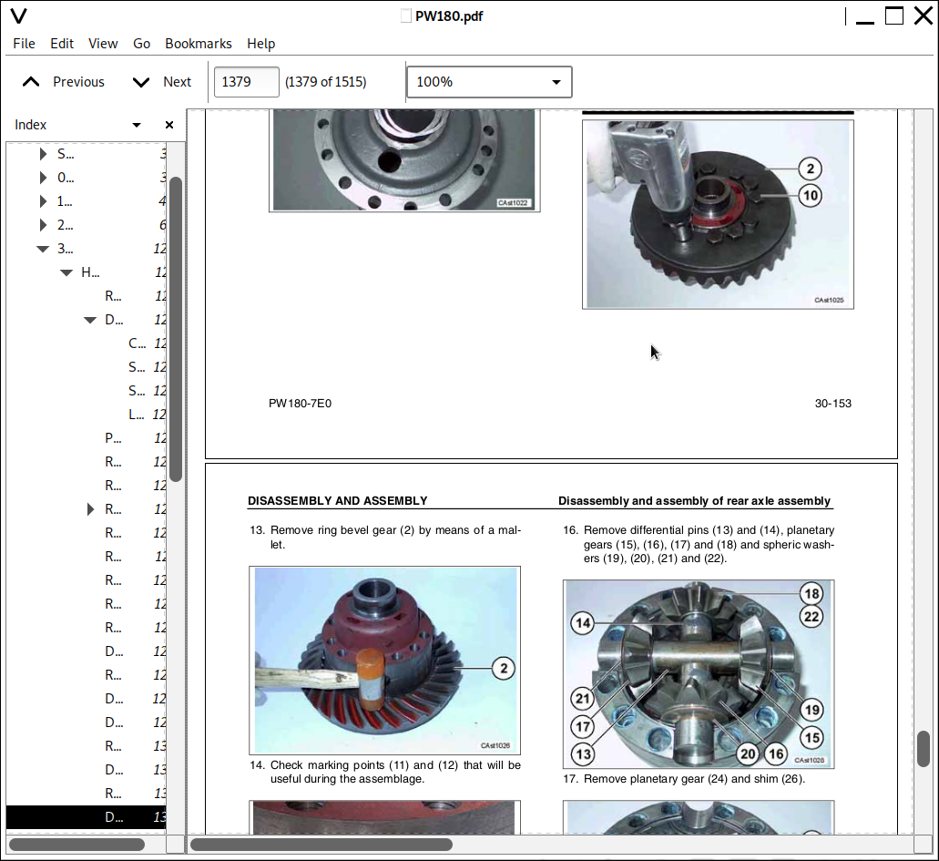
Disassembly and assembly of rear axle assembly.....1365
Disassembly and assembly of transmission.....1393
Removal and installation of propshaft assembly.....1423
Removal and installation of wheel assembly.....1425
Removal and installation of suspension lock cylinder assembly.....1427
Disassembly and assembly of suspension lock cylinder.....1428
Removal and installation of outrigger assembly.....1429
Disassembly and assembly of outriggers.....1431
Removal and installation of dozer blade assembly.....1433
Disassembly and assembly of dozer blade.....1435
Removal and installation of swing circle assembly.....1437
Removal and installation of revolving frame assembly.....1439
Removal and installation of centre swivel joint.....1443
Disassembly and assembly of centre swivel joint assembly.....1447
Removal and installation of fuel tank assembly.....1449
Removal and installation of hydraulic tank assembly.....1451
Removal and installation of control valve assembly.....1455
Removal and installation of LS separation valve assembly.....1459
Removal and installation of pressure compensation valve assembly.....1460
Removal and installation of main relief valve assembly.....1461
Removal and installation of LS control EPC valve.....1462
Removal and installation of EPC solenoid valve assembly.....1463
Removal and installation of PPC solenoid valve block assembly.....1465
Removal and installation of oil seal in hydraulic pump input shaft.....1467
Disassembly and assembly of work equipment PPC valve.....1468
Disassembly and assembly of hydraulic cylinder.....1469
Removal and installation of monoboom work equipment.....1475
Removal and installation of 2 piece boom work equipment.....1479
Removal and installation of air conditioner unit.....1483
Removal and installation of counterweight.....1487
Removal and installation of operator cab assembly.....1489
Removal and installation of monitor assembly.....1493
Removal and installation of pump controller assembly.....1495
90 DIAGRAMS.....1498
HYDRAULIC CIRCUIT DIAGRAM (1/3).....1500
HYDRAULIC CIRCUIT DIAGRAM (2/3).....1502
HYDRAULIC CIRCUIT DIAGRAM (3/3).....1504
ELECTRICAL CIRCUIT DIAGRAM (1/3).....1506
ELECTRICAL CIRCUIT DIAGRAM (2/3).....1508
ELECTRICAL CIRCUIT DIAGRAM (3/3).....1510
![]()