
Komatsu Hydraulic Excavator PC490LC-10, PC490LC-11, PC490LCi-11 Repair Service Manual
Complete service repair manual with Electrical Wiring Diagrams for Komatsu Hydraulic Excavator PC490LC-10, PC490LC-11, PC490LCi-11, with all the technical information to maintain, diagnose, repair, rebuild like professional mechanics.
Komatsu Hydraulic Excavator PC490LC-10, PC490LC-11, PC490LCi-11 workshop service repair manual includes:
* Numbered table of contents easy to use so that you can find the information you need fast.
* Detailed sub-steps expand on repair procedure information
* Numbered instructions guide you through every repair procedure step by step.
* Troubleshooting and electrical service procedures are combined with detailed wiring diagrams for ease of use.
* Notes, cautions and warnings throughout each chapter pinpoint critical information.
* Bold figure number help you quickly match illustrations with instructions.
* Detailed illustrations, drawings and photos guide you through every procedure.
* Enlarged inset helps you identify and examine parts in detail.
PRODUCT DETAILS:
Total Pages: 15,432 pages
File Format: PDF (Internal Links, Bookmarked, Table of Contents, Searchable, Printable, high quality)
Language: English
CEBM025303 - Hydraulic Excavator PC490LC-10 Shop Manual.pdf
CEBM025304 - Hydraulic Excavator PC490LC-10 Shop Manual.pdf
CEBM028301 - Hydraulic Excavator PC490LC-11 Shop Manual.pdf
CEBM031500 - Hydraulic Excavator PC490LCi-11 Shop Manual.pdf
SEN05622-02 - Hydraulic Excavator PC490LC-10 Shop Manual.pdf
SEN06494-03 - Hydraulic Excavator PC490LC-11 Shop Manual.pdf
GEN00109-02 - Hydraulic Excavator PC490LC-10 Field Assembly Instruction.pdf
GEN00126-01 - Hydraulic Excavator PC490LC-11 Field Assembly Instruction.pdf
TEN00520-02 - Hydraulic Excavator PC490LC-10 Operation & Maintenance Manual.pdf
CEAM025504 - Hydraulic Excavator PC490LC-10 Operation & Maintenance Manual.pdf
MAIN SECTIONS
CEAM025504 - Hydraulic Excavator PC490LC-10 Operation & Maintenance Manual...2
CEAM025504 PC490LC-10 S/N A40001 and UP...2
INTRODUCTION - SECTION 0...4
FOREWORD...5
SAFETY INFORMATION...6
Safety labels...7
INTRODUCTION...8
Directions of Machine...8
Visibility from Operators Seat...9
Close Visibility...9
Visibility for a Circumference of 12 m...9
Structure to Protect the Operator...9
Breaking-in the New Machine...10
Product Information...11
Product Identification Number (Pin)/Machine Serial No. Plate...11
EPA* Regulations, Engine Number Plate...11
Service Meter Location...12
Your Machine Serial Numbers and Distributor...12
Engine Acronyms...12
TABLE OF CONTENTS...13
SAFETY - SECTION 1...24
SAFETY LABELS...25
Location Of Safety Labels...25
Safety Labels...26
GENERAL PRECAUTIONS COMMON TO OPERATION AND MAINTENANCE...36
Precautions Before Starting Operation...36
Ensuring Safe Operation...36
Understanding the Machine...36
Preparations for Safe Operation...36
Precautions Regarding Safety-related Equipment...36
Inspecting Machine...36
Clothing and Personal Protective Items...36
Keep Machine Clean...37
Keep Operator's Compartment Clean...37
Fire Extinguisher and First Aid Kit...37
Safety Equipment...37
If Problems are Found...37
Fire Prevention and Explosion Prevention...38
Action if Fire Occurs...39
Handrails and Steps...40
Mounting and Dismounting...40
No Persons on Attachments...40
Leaving Operator's Seat with Lock...41
Emergency Exit from Operator's Cab...41
Do Not Get Caught in Work Equipment...42
Precautions Related to Protective Structures...42
Falling Objects, Flying Objects and Intruding Objects Prevention...42
Unauthorized Modification...43
Precautions Related to Attachments and Options...43
Precautions Related to Cab Glass...43
Precautions When Running Engine inside Building...43
Safety at Jobsite...44
Working on Loose Ground...44
Distance to High Voltage Cables...44
Ensure Good Visibility...45
Signalman's Signal and Signs...45
Asbestos Dust Hazard Prevention...46
SAFETY MACHINE OPERATION...47
Starting Engine...47
Checks Before Starting Engine...47
Safety Rules for Starting Engine...48
Starting Engine in Cold Weather...48
Starting Engine with Booster Cables...48
Operation...49
Checks Before Operation...49
Safety Rules for Changing Machine Directions...49
Safety Rules for Traveling...50
Traveling on Slopes...51
Operations on Slopes...52
Prohibited Operations...53
Operations on Snow or Frozen Surfaces...55
Parking Machine...55
TRANSPORTATION...56
Loading and Unloading...56
Shipping the Machine...56
TOWING...57
Safety Rules for Towing...57
LIFTING OBJECTS WITH BUCKET...58
Safety Rules for Lifting Objects...58
SAFETY MAINTENANCE INFORMATION...59
Warning Tag...59
Keep Work Place Clean and Tidy...59
Select Suitable Place for Inspection and Maintenance...59
Only Authorized Personnel...59
Appoint Leader when Working with Others...59
Stop Engine Before Carrying Out Maintenance...60
Precautions When Working at High Places...60
Two Workers for Maintenance when Engine is Running...61
Attachments...61
Work on Machine...62
Work Under the Machine...62
Proper Tools...62
Battery Disconnect Switch...63
Removing Battery Terminals...63
Welding...63
Battery...63
Battery Hazard Prevention...63
When Using Hammer...64
Precautions with High-temperature Coolant...64
Precautions with High-temperature Oil...65
Safety Rules for High-pressure Oil...65
Precaution for High Fuel Pressure...65
Safety Handling High-pressure Hoses or Piping...65
Precaution for High Voltage...66
Noise...66
Safety First when Using High-pressure Grease to Adjust Track Tension...66
Do Not Disassemble Recoil Springs...67
Accumulator...67
Handling Gas Spring...67
Precautions when Using...67
Precautions when Discarding...68
Compressed Air...68
Air Conditioner Maintenance...68
Waste Materials...68
Select Window Washer Fluid...68
Personnel...68
Periodic Replacement Of Safety Critical Parts...69
OPERATION - SECTION 2...70
MACHINE VIEW ILLUSTRATIONS...71
Overall Machine View...71
General View of Cab...73
CONTROLS AND GAUGES...74
Machine Monitor...75
EXPLANATION OF COMPONENTS...76
Machine Monitor...76
Basic Operation of Machine Monitor...77
Warning Display...82
Meter Display...92
Gauges and Meter...99
Monitor Switches Portion...102
User Menu Selector Switch...115
User Menu...116
Machine Settings...127
Maintenance Screen Setting...136
Monitor Setting...138
Screen Adjustment...138
Screen Adjustment (Camera)...139
Clock Adjustment...139
Time...141
SWITCHES...146
Starting Switch...147
Fuel Control Dial...147
Cigarette Lighter...147
Swing Lock Switch...147
Lamp Switch...148
Horn Switch...148
One Touch Power Max. Switch...148
Room Lamp Switch...148
Emergency Pump Drive Switch...149
Swing Brake Cancel Switch...149
Ceiling Window Wiper Switch...150
Seat Heater Switch...150
Machine Push-up Switch...150
Engine Shutdown Secondary Switch...151
CONTROL LEVERS AND PEDALS...152
Lock Lever...152
Travel Levers...153
Work Equipment Control Lever...154
CEILING WINDOW...155
cab WINDowS...155
EMERGENCY ESCAPE HAMMER...161
DOOR LOCK...162
CAB DOOR HINGE...162
CAPS AND COVERS WITH LOCK...163
Open and Close Caps with Lock...163
Opening the Cap...163
Locking the Cap...163
Open and Close Covers with Lock...164
Opening the Cover (Locked Cover)...164
Locking the Cover...164
Lock and Unlock Engine Hood...164
Opening the Hood (Locked Hood)...164
Locking the Hood...164
Lock and Unlock Cab Door...165
Opening the Door (Locked Door)...165
Locking the Door...165
DRINK BOX...166
MAGAZINE BOX...166
CUP HOLDER...166
ASHTRAY...167
AIR CONDITIONER CONTROLS...168
Air Conditioner Control Panel...168
Method of Operation...173
Automatic Operation...173
Stopping Automatic Operation...174
Manual Operation...174
Stop Manual Operation...176
Operation with Cold Air to Face and Warm Air to Feet...176
Defroster Operation...178
Rules for Using Air Conditioner...180
Air Conditioner Maintenance...180
RADIO...181
Control Panel...181
Operation Method...183
Frequency Adjustment...183
Frequency Adjustment (Auto Presetting)...183
Preset Call...183
Preset Memory...183
Sound Adjustment (Balance)...183
Sound Adjustment (Treble)...184
Sound Adjustment (Bass)...184
Time Adjustment...184
Stowing Radio Antenna...184
AUXILIARY ELECTRIC POWER...185
24 V Power Source...185
12 V Power Source...185
FUSE...186
FUSIBLE LINK...187
TOOL BOX...187
GREASE GUN HOLDER...187
FIRE EXTINGUISHER...188
BATTERY DISCONNECT SWITCH...189
SYSTEM OPERATING LAMP...190
HANDLING KOMATSU DIESEL PARTICULATE FILTER (KDPF)...191
Manual Stationary Regeneration, Operation Procedure...195
Komatsu Diesel Particulate Filter (KDPF) Regeneration Disable Procedure...197
While Regeneration is Not Being Performed: Setting for Regeneration Disable...198
While Regeneration is Being Performed: Stopping Regeneration...200
Re-enabling KDPF Regeneration...201
Handling Komatsu Closed Crankcase Ventilation (KCCV)...201
HANDLING MACHINES EQUIPPED WITH KOMTRAX...202
Basic Precautions...203
MACHINE OPERATIONS AND CONTROLS...204
Before Starting Engine...204
Walk-around Checks...204
Checks Before Starting...206
Adjustment...213
Seat Belt Inspection...222
Seat Belt...223
Operations Before Starting Engine...224
STARTING ENGINE...227
Turbo Protect Function...230
AFTER STARTING ENGINE...231
Engine Warm Up...233
Canceling Automatic Warm-up Operation...234
Hydraulic System Warm-Up...235
Operation After Completion of Warming-Up Operation...241
STOPPING THE ENGINE...243
MACHINE OPERATION...244
Preparations for Moving the Machine...244
Moving Machine Forward...245
Moving Machine Backward...246
Stopping Machine...247
STEERING THE MACHINE...248
Steering...248
Steering the Machine When Stopped (Pivot Turn)...248
Changing Direction of the Machine...249
Counter-rotation Turn (Spin Turn)...249
SWINGING...250
WORK EQUIPMENT CONTROLS AND OPERATIONS...251
WORKING MODE...253
Working Mode Switch...253
One-Touch Power Max. Switch...255
PROHIBITED OPERATIONS...256
GENERAL OPERATION INFORMATION...261
Traveling...261
High Speed Travel...261
Permissible Water Depth...262
TRAVELING ON SLOPES...263
ESCAPE FROM MUD...265
Track on One Side Stuck...265
Tracks on Both Sides Stuck...265
RECOMMENDED APPLICATIONS...266
Backhoe Work...266
Shovel Work...266
Ditching Work...266
Loading Work...267
BUCKET REPLACEMENT AND INVERSION...268
Replacement...268
Inversion...270
PARKING MACHINE...272
MACHINE INSPECTION AFTER DAILY WORK...274
LOCKING...274
TRANSPORTATION...274
Transportation Procedure...274
Loading and Unloading with Trailer...275
Loading...276
Securing Machine...279
Stowing Radio Antenna...281
Installation and Removal of Mirrors...281
Remove and Install Handrail...283
Unloading...284
LIFTING MACHINE...286
Standard Specification Machines...286
Machines with Lifting Hook...288
Spread and Narrow Track Frame Gauge...289
Narrowing Gauge...289
Spreading Gauge...290
COLD WEATHER OPERATION...291
Cold Weather Operation Information...291
Fuel and Lubricants...291
Coolant...291
Battery...292
AFTER DAILY WORK COMPLETION...293
AFTER COLD WEATHER SEASON...293
LONG TERM STORAGE...294
Before Storage...294
During Storage...294
After Storage...295
Starting Machine After Long-term Storage...295
TROUBLES AND ACTIONS...296
Running Out of Fuel...296
Bleeding Air from Fuel Circuit...296
Phenomena that are Not Failures...297
Towing the Machine...298
Lightweight Towing Hole...299
Severe Job Condition...299
Discharged Battery...300
Battery Removal and Installation...300
Battery Charges...301
Starting Engine with Booster Cables...302
OTHER TROUBLE...304
Electrical System...304
Chassis...305
Engine...306
Electronic Control System...308
Point of Contact to Telephone When Error Occurs...308
MAINTENANCE - SECTION 3...310
MAINTENANCE INFORMATION...311
OUTLINE OF SERVICE...313
Handling Oil, Fuel, Coolant, and Performing Oil Clinic...313
Oil...313
Fuel...314
Coolant and Water for Dilution...314
Grease...315
Carrying Out KOWA (Komatsu Oil Wear Analysis)...315
Storing Oil and Fuel...316
Filters...316
Electric System Maintenance...316
WEAR PARTS...317
Wear Parts List...317
RECOMMENDED FUEL, COOLANT, AND LUBRICANT...318
Lubrication Chart...318
Fuel, Coolant, and Lubricants to Match the Ambient Temperature...320
Recommended Brands, Recommended Quality For Products Other Than Komatsu Genuine Oil...321
TORQUE SPECIFICATIONS...322
Torque List...322
Torque of Bolts...322
Torque of Hose Nuts...323
Torque of Split Flange Bolts...323
Torque for Flared Nuts...324
Torque for O-ring Boss Piping Joints...324
Torque for O-ring Boss Plugs...325
Torque for Hoses (Taper Seal Type and Face Seal Type)...325
SAFETY CRITICAL PARTS...326
Safety Critical Parts List...327
MAINTENANCE SCHEDULE...328
Maintenance Schedule Table...328
Maintenance Interval for Hydraulic Breaker...330
MAINTENANCE PROCEDURE...331
Initial 10 Hours Maintenance...331
Initial 250 Hours Maintenance (Only After the First 250 Hours)...331
Initial 500 Hours Maintenance (Only After the First 500 Hours)...331
When Required...332
Check, Clean and Replace Air Cleaner Element...332
Clean Inside of Cooling System...338
Check and Tighten Track Shoe Bolts...344
Check and Adjust Track Tension...345
Replace Bucket Teeth (Vertical Pin Type)...347
Replace Bucket Teeth (Horizontal Pin Type)...350
Replace Bucket Side Cutter, Shroud...352
Adjust Bucket Clearance...353
Check Window Washer Fluid Level, Add Fluid...354
Check and Maintain Air Conditioner...355
Wash Washable Floor...356
Set Machine at Angle...358
Check Gas Spring...359
Bleeding Air from Hydraulic System...360
Clean Line Filter, Remove Dirt...362
Check Before Starting...363
Every 50 Hours Maintenance...364
Lubricating...364
Every 250 Hours Maintenance...365
Check Level of Battery Electrolyte...365
Check Air Conditioner Compressor Belt Tension, Adjust...367
Check and Tighten Connecting Bolt Between Center Frame and Track Frame...368
Lubricate Swing Circle...368
Every 500 Hours Maintenance...369
Lubricating...369
Change Oil in Engine Oil Pan...371
Replace Engine Oil Filter Cartridge...371
Replace Fuel Pre-filter Cartridge...372
Check Swing Pinion Grease Level, Add Grease...374
Clean and Inspect Radiator Fins, Oil Cooler Fins, Aftercooler Fins, Fuel Cooler Fins, and Condenser Fins...375
Clean Air Conditioner Fresh/Recirc Filters...377
Replace Breather Element in Hydraulic Tank...379
Check Oil Level in Swing Machinery Case, Add Oil...380
Check Oil Level in Final Drive Case, Add Oil...381
Every 1000 Hours Maintenance...382
Replace Hydraulic Oil Filter Element...382
Change Oil in Swing Machinery Case...383
Check Oil Level in Damper Case, Add Oil...384
Replace Fuel Main Filter Cartridge...385
Check All Tightening Points of Engine Exhaust Pipe Clamps...388
Check Alternator/Fan Belt Tension and Replace Belt...388
Check Nitrogen Gas Charge Pressure in Accumulator (for Breaker)...388
Replace Additional Breather Element in Hydraulic Tank...388
Every 2000 Hours Maintenance...389
Change Oil in Final Drive Case...389
Clean Hydraulic Tank Strainer...390
Check Charge Pressure of Nitrogen Gas in Accumulator (for Control Circuit)...391
Check Alternator...394
Check Engine Valve Clearance, Adjust...394
Replace Komatsu Closed Crankcase Ventilation (KCCV) Filter Element...395
Every 4000 Hours Maintenance...398
Check Water Pump...398
Check Starting Motor...398
Replace Accumulator (for Control Circuit)...399
Check for Looseness of High-pressure Piping Clamp, Hardening of Rubber...400
Check for Missing Fuel Spray Prevention Cap, Hardening of Rubber...400
Every 4500 Hours Maintenance...401
Clean Komatsu Diesel Particulate Filter (KDPF)...401
Clean Fuel Doser...401
Check for Missing Fuel Spray Prevention Cap of Fuel Doser Piping, Hardening of Rubber...401
Every 5000 Hours Maintenance...402
Change Oil in Hydraulic Tank...402
Every 8000 Hours Maintenance...404
Replace Fuel Spray Prevention Cap...404
Replace High-pressure Piping Clamp...404
EVERY 9000 HOURS MAINTENANCE...404
Replacement of Fuel Spray Prevention Cap of Fuel Doser Piping...404
SPECIFICATIONS - SECTION 4...406
SPECIFICATIONS...407
OPTIONS, ATTACHMENTS - SECTION 5...410
GENERAL PRECAUTIONS FOR SAFETY...411
Precautions When Selecting...411
Read the Operation and Maintenance Manual Thoroughly...411
Precautions When Removing or Installing...411
Precautions When Using...411
BUCKET WITH HOOK...412
Hook Condition...412
Safety Rules for Lifting Operations...412
CHANGING DIRECTION OF THE MACHINE...413
Straight Travel (Option)...414
CHANGING MACHINE CONTROL PATTERN...415
Control Pattern Change Procedure...415
MACHINE READY FOR ATTACHMENT...417
Locations...417
Stop Valve...417
Selector Valve...418
Attachment Control Pedal...418
Lock Pin...418
Breaker Circuit Additional Oil Filter...419
Accumulator...420
HYDRAULIC CIRCUIT...421
Switching Hydraulic Circuit...421
Switching Between Breaker and General Attachment...421
Hydraulic Circuit Connection...422
Oil Flow Path...423
Replace Additional Breaker Filter Element...424
Replace Additional Breaker Pilot Filter Element...426
ATTACHMENT REMOVAL AND INSTALLATION...429
Attachment Removal...429
Attachment Installation...431
ATTACHMENT OPERATIONS...433
When Using Breaker...433
When Using General Attachment Such as Crusher...436
LONG TERM STORAGE...437
SPECIFICATIONS...437
Attachment Guide...438
Attachment Combinations...438
TRACK SHOES SELECTION...440
Selection Method of Track Shoe...440
HANDLING COUNTERWEIGHT REMOVER...441
Explanation of Components...441
Counterweight...441
Remover Link...441
Remover Link Cylinder...441
Counterweight Remover Control Lever...442
Remover Control Selector Valve...442
Operation of Counterweight Remover...443
Lowering Counterweight...444
Installing Counterweight...447
Greasing...450
BUCKET TEETH SELECTION...451
Selection Guide for Horizontal or Vertical Pin Type Tooth...451
Handling Trapezoidal Bucket...452
Digging Work...452
HANDLING EXTENSION ARM...454
HANDLING CLAMSHELL BUCKET...455
RECOMMENDED ATTACHMENT OPERATIONS...456
Hydraulic Breaker...456
Prohibited Usage...458
CEBM025303 - Hydraulic Excavator PC490LC-10 Shop Manual...462
CEBM025303...462
CONTENTS...463
SAFETY...478
Safety Notice...478
Important Safety Notice...478
General Precautions...478
Preparations For Work...480
Precautions During Work...480
GENERAL...483
HOW TO READ THE SHOP MANUAL...485
Volumes...485
Distribution And Updating...485
Filing Method...485
Revised Edition Mark...485
Revisions...485
Symbols...485
HOISTING INSTRUCTIONS...486
Hoisting...486
Making Signs...486
Precautions...486
Precautions for Sling Work...486
Precautions for Using Mobile Crane...487
Precautions for Using Overhead Hoist Crane...487
Selecting Wire Ropes...488
HANDLING ELECTRIC EQUIPMENT AND HYDRAULIC COMPONENTS...489
Points to Remember When Handling Electric Equipment...489
Points to Remember When Handling Hydraulic Equipment...500
PUSH PULL COUPLER...502
Type 1...502
Disconnection...502
Connection...502
Type 2...503
Disconnection...503
Connection...503
Type 3...504
Disconnection...504
Connection...504
EXPLANATION OF MAINTENANCE STANDARD TERMS...505
HANDLING OF FUEL SYSTEM DEVICES...506
HANDLING OF INTAKE SYSTEM PARTS...507
STANDARD TIGHTENING TORQUE...508
Bolts And Nuts...508
Tightening Torque Of Hose Nuts...509
Tightening Torque Of Split Flange Bolts...509
Tightening Torque For Flared Nuts...509
Tightening Torques for Split Flanged Bolts...510
Tightening Torques For O-ring Boss Piping Joints...510
Table Of Tightening Torques For O-ring Boss Plugs...510
Tightening Torque For Hoses (Taper Seal Type And Face Seal Type)...511
Tightening Torque For Face Seal Joints...511
ELECTRIC WIRE CODE...512
Classification By Thickness...512
Classification By Color And Code...512
How To Read Electric Wire Code...513
PRECAUTIONS FOR OPERATIONS...516
Precautions when Carrying Out Removal Work...516
Precautions when Carrying Out Installation Work...517
Precautions when Completing the Operation...518
CONVERSION TABLES...519
Method Of Using The Conversion Table...519
COATING MATERIALS...525
LIST OF ABBREVIATIONS...527
List of Abbreviations Used in the Shop Manual...527
List of Abbreviations Used in the Circuit Diagrams...531
01 GENERAL...532
SPECIFICATION DIMENSION DRAWINGS...533
Dimensions...533
Working Ranges...534
SPECIFICATIONS...535
WEIGHT TABLE...539
FUEL, COOLANT AND LUBRICANTS...541
10 STRUCTURE, FUNCTION & MAINTENANCE STD...544
ENGINE AND COOLING SYSTEM...547
Engine Related Parts...547
Radiator, Oil Cooler and Aftercooler...549
Cooling Fan Pump...551
Operation of Pump...554
Control of Delivery...557
Servo Valve...558
Cooling Fan Motor...560
Hydraulic Motor...562
Suction Valve...563
Reversible Valve...565
Safety Valve...567
POWER TRAIN SYSTEM...569
Power Train...569
Swing Circle...571
Swing machinery...573
Final Drive...575
UNDERCARRIAGE AND FRAME...577
Track Frame and Idler Cushion...577
HYDRAULIC SYSTEM...579
Hydraulic Component Layout...579
Valve Control...581
Hydraulic Tank...582
Oil Filler Port Cap...583
CLSS...585
Structure of CLSS...585
Basic Principle...586
Main Pump...591
LS valve...596
Operation...597
PC Valve...601
Operation...603
LS(PC)-EPC Valve...609
Operation...610
Control Valve...613
Functions and Operation by Valve...625
Unload Valve...629
LS Bypass Valve...631
Pressure Compensation Valve...632
Pressure Compensation Valve Inner Shuttle Valve...635
Boom Regeneration Circuit...637
Arm Regeneration Circuit...639
Merge-Divider Valve...641
LS Select Valve...644
Self Pressure Reducing Valve...645
Travel Junction Valve...648
Travel PPC Shuttle Valve...651
Boom Hydraulic Drift Preventive Valve...653
Arm Drift Preventive Valve...656
Suction Safety Valve For Drift Prevention Valve...659
Arm Quick Return Valve...660
Variable Back Pressure Valve...662
Main Relief Valve...663
2-Stage Safety-Suction Valve...665
Swing Motor...667
Swing Holding Brake...669
Swing 2-Stage Relief Valve...672
Swing Motor Reverse Prevention Valve...673
Travel Motor...676
Operation of Motor...679
Operation of Parking Brake...681
Brake Valve...683
Safety Valve (Bidirectional 2-Stage Set Safety Valve)...684
PPC Valve...688
Work Equipment and Swing PPC Valve...688
Travel PPC valve...694
1st-line Attachment PPC Valve (with EPC valve)...698
EPC valve...699
Solenoid Valve...703
Attachment Circuit Selector Valve...705
Center Swivel Joint...707
PPC Accumulator...708
WORK EQUIPMENT...709
Work Equipment...709
Work Equipment Shims...710
CAB AND ITS ATTACHMENTS...711
Cab Mount and Cab Tipping Stopper...711
ROPS Cab...712
ELECTRICAL SYSTEM...713
Engine Control...713
Engine Controller Function...716
Engine And Pump Combined Control Function...719
Pump and Valve Control Function...725
One-touch Power Maximizing Function...727
Machine Push-up Function...729
Auto-Deceleration Function...731
Engine Automatic Warm-up Function...733
Overheat Prevention Function...735
Turbocharger Protection Function...736
Swing Control Function...737
Quick Warm-Up Function...739
Swing 2-Stage Relief Function...739
Travel Control Function...741
PPC Lock Function...743
Oil Flow Adjuster Function For Attachment...745
Hydraulic Fan Control Function...747
Fan Rotation Control...747
Engine Output Control...748
Fan Reverse Rotation Function...749
System Component Part...751
Pump Controller...755
Resistor for PC-EPC valve...760
CAN Terminating Resistor...761
MACHINE MONITOR SYSTEM...762
Machine Monitor...763
Input and Output Signals...764
Display...767
Gauges...769
Caution Monitor...771
Pilot Monitor...775
Switches...777
Guidance ICON and Function Switch...779
Operator Mode Function...783
Service Mode Function...785
KOMTRAX SYSTEM...787
KOMTRAX Terminal...788
Input and Output Signals...789
SENSORS...791
Ambient Pressure Sensor...791
Engine Oil Pressure Sensor...792
Charge Pressure Sensor...792
Charge Temperature Sensor...793
Coolant Temperature Sensor...793
Ne (Crankshaft) Speed Sensor...794
Bkup (Camshaft) Speed Sensor...794
Common Rail Pressure Sensor...795
EGR Valve Lift Sensor...796
KVGT Speed Sensor...797
KVGT Position Sensor...797
Mass Air Flow and Temperature Sensor...798
Dosing Fuel Pressure Sensor...799
KDPF Differential Pressure and Outlet Pressure Sensor...799
KDOC Inlet Temperature Sensor...800
KDOC Outlet Temperature Sensor...800
KDPF Outlet Temperature Sensor...801
Crankcase Pressure Sensor...801
Engine Oil Level Sensor...802
Fuel Level Sensor...803
Coolant Level Sensor...804
Hydraulic Oil Temperature Sensor...804
Front Pump Oil Pressure Sensor...805
Rear Pump Oil Pressure Sensor...806
PPC Oil Pressure Sensor...807
Air Cleaner Clogging Sensor...808
Front Pump Swash Plate Sensor...809
Rear Pump Swash Plate Sensor...810
Cooling Fan Speed Sensor...811
20 STD VALUE TABLES...812
STANDARD SERVICE VALUE TABLES...813
Standard Value Table for Engine...813
Standard Value Table for Machine...815
Engine Speed...815
Travel of Control Valve Spool...815
Travel of Control Lever...816
Operating Effort of Control Lever and Pedal...816
Hydraulic Oil Pressure...817
Swing...818
Travel...819
Work Equipment...821
Performance in Combined Operation...823
Pump Swash Plate Sensor...823
Characteristics of PC Flow Control...823
Fan...824
Main Pump...824
Posture of Machine for Measuring Performance and Measurement Procedure...826
Control Valve: Spool Travel...826
Swing 1: Overrun When Stopping Swing, Time Taken to Start Swing, Time Taken to Swing...826
Swing 2: Amount of Hydraulic Drift of Swing...826
Travel 1: Travel Speed, Idle Running (Without Load)...826
Travel 2: Travel Speed (Actual Run), Travel Deviation...827
Travel 3: Travel Deviation...827
Travel 4: Hydraulic Drift of Travel...827
Work Equipment 1: Hydraulic Drift of Work Equipment...827
Work Equipment 2: Boom Speed...828
Work Equipment 3: Arm Speed...828
Work Equipment 4: Bucket Speed...828
Work Equipment 5: Boom Time Lag...828
Work Equipment 6: Arm Time Lag...829
Work Equipment 7: Bucket Time Lag...829
Work Equipment 8: PC Flow Characteristics Control...829
30 TESTING & ADJUSTING...830
GENERAL INFORMATION...833
Tools for Testing, Adjusting, and Troubleshooting...833
Sketch of Tools for Testing and Adjusting...839
ENGINE AND COOLING SYSTEM...843
Checking Engine Speed...843
Measuring Boost Pressure...845
Measuring Exhaust Gas Temperature...847
Measuring Exhaust Gas Color...849
Measuring and Adjusting Valve Clearance...851
Testing...851
Adjusting...854
Measuring Compression Pressure...855
Measuring Engine Oil Pressure...860
Measuring EGR Valve and KVGT Oil Pressure...862
Measuring Fuel Pressure...864
Measuring Fuel Leakage and Return...866
Testing...866
Measuring return rate from injector...868
Bleeding Air from Fuel System...870
Bleeding Air...871
Checking Fuel Circuit for Leakage...874
Handling Cylinder Cut-Out Mode Operation...875
Handling No-Injection Cranking Operation...875
Checking and Adjusting Air Conditioner Compressor Belt Tension...876
Checking...876
Adjusting...877
Replacing Fan Belt...878
Replacing...878
Fuel Doser Cleaning Procedure...880
Removal...880
Cleaning...881
Installation...883
Writing Compensation Values at Replacement of Injector and Engine Controller...884
Connection of PC...884
Starting INSITE...885
POWER TRAIN...890
Testing Swing Circle Bearing Clearance...890
Testing...890
UNDERCARRIAGE AND FRAME...892
Testing and Adjusting Track Shoe Tension...892
Testing...892
Adjusting...892
HYDRAULIC SYSTEM...894
Releasing Remaining Pressure from Hydraulic Circuit...894
Measuring and Adjusting of Oil Pressure in Work Equipment, Swing, and Travel Circuits...896
Testing...896
Adjusting...898
Measuring Oil Pressure in Control Circuit...902
Measuring and Adjusting Oil Pressure in Pump PC Control Circuit...904
Testing...904
Adjusting...906
Measuring and Adjusting Oil Pressure in Pump LS Control Circuit...908
Testing...908
Checking Oil Pressure with Sensor Adapter (Special Tool)...912
Adjusting...913
Measuring Solenoid Valve Output Pressure...914
Testing...914
Operating Condition...916
Measuring PPC Valve Output Pressure...918
Adjusting Play of Work Equipment and Swing PPC Valves...920
Testing Pump Swash Plate Sensor...921
Measuring Fan Pump Circuit Oil Pressure...922
Checking Fan Pump EPC Current...923
Measuring Fan Pump EPC Solenoid Valve Output Pressure...924
Isolating the Parts Causing Hydraulic Drift in Work Equipment...926
Measuring Oil Leakage...928
Bleeding Air From Hydraulic Circuit...932
Bleeding Air...933
CAB AND ITS ATTACHMENTS...936
Checking Cab Tipping Stopper...936
Adjusting Mirrors...937
ELECTRICAL SYSTEM...940
Special Functions of Machine Monitor...940
Upper Part Of Machine Monitor (Display Portion)...941
Upper Part of Machine Monitor (Switch Portion)...941
Lower Part of Machine Monitor (Switch Portion)...941
Ordinary Functions and Special Functions of Machine Monitor...941
Operator Mode (Outline)...944
Service Mode...963
Angle Adjustment of Rear View Camera...1027
Handling Voltage Circuit of Engine Controller...1029
Handling Battery Disconnect Switch...1030
Testing Diodes...1031
PM CLINIC...1032
PM Clinic Service...1032
Check Items Related to Engine...1034
Check Items Related to Oil Pressure...1035
Check Sheet...1036
1. Engine...1036
2. Work equipment speed...1037
3. Hydraulic drift of work equipment...1037
4. Hydraulic circuit...1038
Visual Check of Welded Structures...1041
Undercarriage Inspection Report...1042
40 TROUBLESHOOTING...1044
GENERAL INFORMATION ON TROUBLESHOOTING...1052
Points to Remember When Troubleshooting...1052
Sequence of Events in Troubleshooting...1054
Checks Before Troubleshooting...1056
Testing Procedure Before Troubleshooting...1058
Walk-Around Check...1058
Checking in Accordance with Checking Procedure...1060
Preparation Work for Troubleshooting of Electrical System...1066
Preparation Work...1066
Classification and Procedure for Troubleshooting...1071
Classification of Troubleshooting...1071
Procedure for Troubleshooting...1071
Symptom of Probable Failure and Troubleshooting No...1075
Information Mentioned in Troubleshooting Table...1079
DIAGNOSTIC PROCEDURE FOR WIRING HARNESS...1081
Open Circuit Of Pressure Sensor System...1081
Connector list...1084
Layout of connectors...1089
Connection Table for Connector Pin Numbers...1095
T-Branch Box and T-Branch Adapter Table...1130
Fuse List and Location...1134
Connection Table of Fuse Box...1134
Locations of Fusible Links...1135
Location of Fuse Box and Fuse Numbers...1135
Precautions for Cleaning and Replacing KDPF (KCSF, KDOC)...1136
FAILURE CODE (DISPLAY OF CODE)...1139
Failure Codes Table...1139
879AKA - Air Conditioner Inner Sensor Disconnection...1146
879AKB - Air Conditioner Inner Sensor Disconnection...1146
879BKA - A/C Outer Sensor Open Circuit...1146
879BKB - A/C Outer Sensor Short Circuit...1146
879CKA - Ventilating Sensor Open Circuit...1146
879CKB - Ventilating Sensor Short Circuit...1146
879DKZ - Sunlight Sensor Open or Short Circuit...1146
879EMC - Ventilation Damper Abnormality...1147
879FMC - Air Mix Damper Abnormality...1147
879GKX - Refrigerant Abnormality...1147
989L00 - Engine Controller Lock Caution 1...1148
989M00 - Engine Controller Lock Caution 2...1148
989N00 - Engine Controller Lock Caution 3...1149
A1U0N3 - KDPF Dry Request (HC Release) 1...1150
A1U0N4 - KDPF Dry Request (HC Release) 2...1152
AA10NX - Air Cleaner Clogging...1155
AB00KE - Charge Voltage Low...1157
B@BAZG - Engine Oil Pressure Low...1159
B@BAZK - Eng Oil Level Low...1161
B@BCNS - Engine Coolant Overheat...1163
B@BCZK - Radiator Coolant Level Low...1165
B@HANS - Hyd Oil Overheat...1167
CA115 - Eng Ne and Bkup Speed Sens Error...1168
CA122 - Chg Air Press Sensor High Error...1169
CA123 - Chg Air Press Sensor Low Error...1171
CA131 - Throttle Sensor High Error...1173
CA132 - Throttle Sensor Low Error...1175
CA135 - Eng Oil Press Sensor High Error...1177
CA141 - Eng Oil Press Sensor Low Error...1179
CA144 - Coolant Temp Sens High Error...1181
CA145 - Coolant Temp Sens Low Error...1183
CA153 - Chg Air Temp Sensor High Error...1185
CA154 - Chg Air Temp Sensor Low Error...1187
CA187 - Sensor 2 Supply Volt Low Error...1189
CA221 - Ambient Press Sensor High Error...1191
CA222 - Ambient Press Sensor Low Error...1193
CA227 - Sensor 2 Supply Volt High Error...1195
CA234 - Eng Overspeed...1196
CA238 - Ne Speed Sensor Supply Volt Error...1197
CA239 - Ne Speed Sens Supply Volt High Error...1199
CA271 - IMV/PCV1 Short Error...1201
CA272 - IMV/PCV1 Open Error...1203
CA273 - PCV2 Short Error...1205
CA274 - PCV2 Open Error...1207
CA322 - Inj #1 (L#1) Open/Short Error...1209
CA323 - Inj #5 (L#5) Open/Short Error...1211
CA324 - Inj #3 (L#3) Open/Short Error...1213
CA325 - Inj #6 (L#6) Open/Short Error...1215
CA331 - Inj #2 (L#2) Open/Short Error...1217
CA332 - Inj #4 (L#4) Open/Short Error...1219
CA343 - ECM Critical Internal Failure...1221
CA351 - Injectors Drive Circuit Error...1222
CA352 - Sensor 1 Supply Volt Low Error...1223
CA356 - Mass Air Flow Sensor High Error...1225
CA357 - Mass Air Flow Sensor Low Error...1227
CA386 - Sensor 1 Supply Volt High Error...1229
CA441 - Battery Voltage Low Error...1231
CA442 - Battery Voltage High Error...1233
CA449 - Rail Press Very High Error...1234
CA451 - Rail Press Sensor High Error...1235
CA452 - Rail Press Sensor Low Error...1237
CA515 - Rail Press Sens Sup Volt Low Error...1239
CA516 - Rail Press Sens Sup Volt High Error...1241
CA553 - Rail Press High Error...1243
CA555 - Crankcase Press High Error 1...1244
CA556 - Crankcase Press High Error 2...1245
CA559 - Supply Pump Press Low Error 1...1246
CA595 - Turbo Speed High Error 2...1250
CA687 - Turbo Speed Low Error...1251
CA689 - Eng Ne Speed Sensor Error...1253
CA691 - Intake Air Temp Sens High Error...1255
CA692 - Intake Air Temp Sens Low Error...1257
CA697 - ECM Internal Temp Sensor High Error...1259
CA698 - ECM Internal Temp Sensor Low Error...1260
CA731 - Eng Bkup Speed Sens Phase Error...1261
CA778 - Eng Bkup Speed Sensor Error...1262
CA1117 - Partial Data Lost Error...1265
CA1664 - KDOC Malfunction...1267
CA1691 - Regeneration Ineffective...1269
CA1695 - Sensor 5 Supply Volt High Error...1273
CA1696 - Sensor 5 Supply Volt Low Error...1275
CA1843 - Crankcase Press Sens High Error...1277
CA1844 - Crankcase Press Sens Low Error...1279
CA1879 - KDPF Differential P Sensor High Error...1282
CA1881 - KDPF Differential P Sensor Low Error...1284
CA1883 - KDPF Differential Pressure Sensor In Range Error...1286
CA1921 - KDPF Soot Load High Error 1...1290
CA1922 - KDPF Soot Load High Error 2...1292
CA1923 - Doser Solenoid Valve 1 High Error...1297
CA1924 - Fuel Doser Sol Valve 1 Low Error...1299
CA1925 - Doser Solenoid Valve 1 In Range Error...1302
CA1927 - Doser Fuel Pressure Sensor High Error...1305
CA1928 - Doser Fuel Pressure Sensor Low Error...1307
CA1942 - Crankcase Press Sens In Range Error...1309
CA1963 - Doser Solenoid Valve 1 Servo Error...1311
CA1977 - Doser Open Short Circuit Error...1313
CA1993 - KDPF Differential Pressure Low Error...1315
CA2185 - Throt Sensor Sup Volt High Error...1317
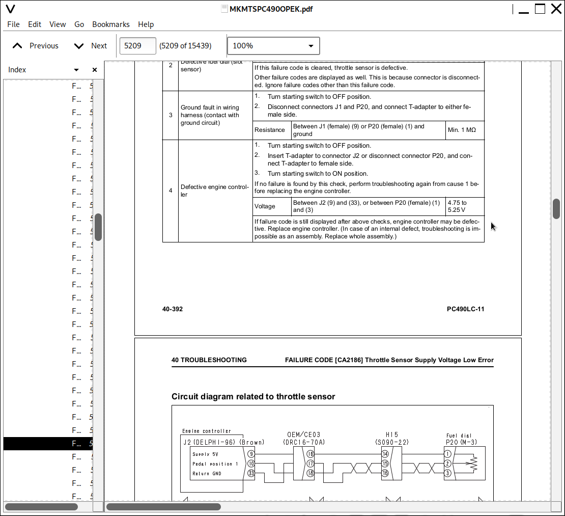
CA2186 - Throt Sensor Sup Volt Low Error...1319
CA2249 - Rail Press Very Low Error...1321
CA2265 - Fuel Feed Pump Open Error...1323
CA2266 - Fuel Feed Pump Short Error...1325
CA2271 - EGR Valve Pos Sens High Error...1327
CA2272 - EGR Valve Pos Sens Low Error...1329
CA2349 - EGR Valve Solenoid Low Error...1331
CA2353 - EGR Valve Solenoid current High Error...1333
CA2357 - EGR Valve Servo Error...1335
CA2373 - Exhaust Manifold Press Sens High Error...1337
CA2374 - Exhaust Manifold Press Sens Low Error...1339
CA2375 - EGR Orifice Temp Sens High Error...1341
CA2376 - EGR Orifice Temp Sens Low Error...1343
CA2381 - KVGT Pos Sens High Error...1345
CA2382 - KVGT Pos Sens Low Error...1347
CA2383 - KVGT Solenoid Open Error...1351
CA2386 - KVGT Solenoid Short Error...1353
CA2387 - KVGT Valve Servo Error...1355
CA2554 - Exh Manifold Press Sens In Range Error...1356
CA2555 - Grid Htr Relay Open Circuit Error...1357
CA2556 - Grid Htr Relay Volt High Error...1359
CA2637 - KDOC Blocked...1361
CA2639 - Manual Stationary Regeneration Request...1363
CA2732 - Dozer Solenoid Valve 2 High Error...1365
CA2733 - Doser Solenoid Valve 2 Low Error...1367
CA2741 - Dozer Solenoid Valve 1 Connection Error...1369
CA2765 - Injector Trim Data Mismatch...1371
CA2878 - Doser Solenoid Valve 2 Servo Error...1373
CA2973 - Chg Air Press Sensor In Range Error...1380
CA3133 - KDPF Outlet Press Sens High Error...1381
CA3134 - KDPF Outlet Press Sens Low Error...1383
CA3135 - KDPF Outlet Press Sens In Range Error...1385
CA3251 - KDOC Inlet Temp High Error...1389
CA3253 - KDOC Temp Error - Non Regeneration...1392
CA3254 - KDOC Outlet Temp High Error 1...1394
CA3255 - KDPF Temp Error - Non Regeneration...1397
CA3256 - KDPF Outlet Temp High Error 1...1398
CA3311 - KDOC Outlet Temp High Error 2...1399
CA3312 - KDPF Outlet Temp High Error 2...1400
CA3313 - KDOC Inlet Temp Sensor Low Error...1403
CA3314 - KDOC Inlet Temp Sens High Error...1407
CA3315 - KDOC Inlet Temp Sens In Range Error...1411
CA3316 - KDOC Outlet Temp Sens Low Error...1415
CA3317 - KDOC Outlet Temp Sens High Error...1419
CA3318 - KDOC Outlet Temp Sens In Range Error...1423
CA3319 - KDPF Outlet Temp Sens High Error...1427
CA3321 - KDPF Outlet Temp Sens Low Error...1431
CA3322 - KDPF Outlet Temp Sens In Range Error...1435
CA3419 - Mass Air Flow (MAF) Sensor Sup Volt High Error...1439
CA3421 - Mass Air Flow (MAF) Sensor Sup Volt Low Error...1441
D110KB - Battery Relay Output Voltage...1443
D19JKZ - Personal Code Relay Abnormality...1445
D811MC - KOMTRAX Error...1448
D862KA - GPS Antenna Open Circuit...1448
D8AQKR - CAN2 Discon (KOMTRAX)...1453
DA20MC - Pump Controller...1454
DA22KK - Pump Solenoid Power Low Error...1455
DA25KP - 5 V Sensor 1 Power Abnormality...1457
DA29KQ - Model Selection Abnormality...1461
DA2QKR - CAN2 Discon (Pump Con)...1469
DA2RKR - CAN1 Discon (Pump Con)...1472
DAF0MB - Monitor Memory Error...1473
DAF0MC - Monitor Error...1474
DAF8KB - Camera Power Supply Short Circuit...1475
DAF9KQ - Model Selection Abnormality...1477
DAFGMC - GPS Module Error...1478
DAFQKR - CAN2 Discon...1483
DAZ9KQ - A/C Model Selection Abnormality...1484
DAZQKR - CAN2 Discon (AC)...1485
DB2QKR - CAN2 Discon (Engine Con)...1491
DB2RKR - CAN1 Discon (Engine Con)...1497
DGH2KA - Hyd Oil Temp Sensor Open...1503
DGH2KB - Hyd Oil Temp Sensor Short Circuit...1505
DHA4KA - Air Cleaner Clog Sensor Open Circuit...1507
DHPAMA - F Pump Press Sensor Abnormality...1508
DHPBMA - R Pump Press Sensor Abnormality...1511
DHS3MA - Arm In PPC Press Sensor Abnormality...1514
DHS4MA - Bucket Curl PPC Press Sensor Abnormality...1517
DHS8MA - Boom Raise PPC Press Sensor Abnormality...1521
DHS9MA - Boom Lower PPC Press Sensor Abnormality...1525
DHSAMA - Swing RH PPC Press Sensor Abnormality...1529
DHSBMA - Swing LH PPC Press Sensor Abnormality...1533
DHSCMA - Arm Out PPC Press Sensor Abnormality...1537
DHSDMA - Bucket Dump PPC Press Sensor Abnormality...1541
DHSFMA - Travel Fwd LH PPC Press Sensor Abnormality...1545
DHSGMA - Travel Fwd RH PPC Press Sensor Abnormality...1549
DHSHMA - Travel Rev LH PPC Press Sensor Abnormality...1553
DHSJMA - Travel Rev RH PPC Press Sensor Abnormality...1557
DKR0MA - F Pump Swash Plate Sensor Abnormality...1561
DKR1MA - R Pump Swash Plate Sensor Abnormality...1565
DLM3KB - Fan Speed Sensor: Short circuit...1571
DV20KB - Travel Alarm Short Circuit...1573
DW43KA - Travel Speed Sol Open Circuit...1575
DW43KB - Travel Speed Sol Short Circuit...1577
DW45KA - Swing Brake Sol Open Circuit...1579
DW45KB - Swing Brake Sol Short Circuit...1583
DW91KA - Travel Junction Sol Open Circuit...1591
DW91KB - Travel Junction Sol Short Circuit...1593
DWA2KA - Attachment Sol Open Circuit...1595
DWA2KB - Attachment Sol Short Circuit...1597
DWK0KA - 2-Stage Relief Sol Open Circuit...1599
DWK0KB - 2-Stage Relief Sol Short Circuit...1601
DWK2KA - Variable Back Press Sol Open Circuit...1603
DWK2KB - Variable Back Press Sol Short Circuit...1605
DWK8KA - Swing Press Cut-Off Sol Open Circuit...1607
DWK8KB - Swing Press Cut-Off Sol Short Circuit...1609
DXA8KA - PC-EPC (F) Sol Open Circuit...1615
DXA8KB - PC-EPC (F) Sol Short Circuit...1617
DXA9KA - PC-EPC (R) Sol Open Circuit...1619
DXA9KB - PC-EPC (R) Sol Short Circuit...1623
DXE0KA - LS-EPC Sol Open Circuit...1625
DXE0KB - LS-EPC Sol Short Circuit...1627
DXE4KA - Attachment Flow EPC Open Circuit...1629
DXE4KB - Attachment Flow EPC Short Circuit...1631
DXE5KA - Merge-divide Main Sol Open Circuit...1633
DXE5KB - Merge-divide Main Sol Short Circuit...1635
DXE6KA - Merge-divide LS Sol Open Circuit...1637
DXE6KB - Merge-divide LS Sol Short Circuit...1639
DY20KA - Wiper Working Abnormality...1641
DY20MA - Wiper Parking Abnormality...1645
DY2EKB - Wiper Drive (Rev) Short Circuit...1649
ELECTRICAL SYSTEM (E-MODE)...1651
E-1 Engine Does Not Start (Engine Does Not Rotate)...1651
E-2 Manual Pre-Heating System Does Not Work...1659
E-3 Automatic Pre-Heating System Does Not Work...1663
E-4 Pre-Heating Monitor Does Not Light Up When Pre-Heater is Operated...1665
E-5 When Starting Switch is Turned to ON Position, Machine Monitor Displays Nothing...1667
E-6 When Starting Switch is Turned to ON Position (Before Starting Engine), Engine Oil Level Monitor Lights Up in Yellow...1670
E-7 When Starting Switch is Turned to ON Position (Before Starting Engine), Radiator Coolant Level Monitor Lights Up in Yellow...1670
E-8 Coolant Temperature Monitor Lights Up in White While Engine is Running...1671
E-9 Hydraulic Oil Temperature Monitor Lights Up in White While Engine is Running...1671
E-10 Charge Level Monitor Lights Up While Engine is Running...1672
E-11 Fuel Level Monitor Lights Up in Red While Engine is Running...1672
E-12 Air Cleaner Clogging Monitor Lights Up in Yellow While Engine is Running...1672
E-13 Engine Coolant Temperature Monitor Lights Up in Red While Engine is Running...1673
E-14 Hydraulic Oil Temperature Monitor Lights Up in Red While Engine is Running...1673
E-15 Engine Oil Pressure Monitor Lights Up in Red While Engine is Running...1674
E-16 Fuel Gauge Display Does Not Move from Minimum or Maximum...1675
E-17 Display of Fuel Gauge Differs from Actual Fuel Level...1677
E-18 Coolant Temperature Gauge Indicate Either Min or Max and Does Not Move...1678
E-20 Hydraulic Oil Temperature Gauge Indicate Either Min or Max and Does Not Move...1681
E-21 Hydraulic Oil Temperature Gauge Differs from Actual oil Temperature...1683
E-22 Machine Monitor Does Not Display Partially...1684
E-23 Function Switch Does Not Work...1684
E-24 Automatic Pre-Heating System Does Not Work (In Cold Weather)...1685
E-25 Auto-Deceleration Monitor Does Not Light Up or Does Not Go Out When Auto-Deceleration Switch is Operated...1686
E-26 Auto-Deceleration is Not Actuated or Canceled When Lever is Operated...1687
E-27 Working Mode Selector Screen Selection Screen is Not Displayed When Working Mode Switch is Operated...1688
E-28 Engine or Hydraulic Pump Setting Does Not Change When Working Mode is Changed...1688
E-29 Travel Speed Monitor Does Not Change When Travel Speed Switch is Operated...1688
E-30 Travel Speed Does Not Change When Travel Speed is Shifted...1689
E-31 Alarm Buzzer Does Not Stop Sounding...1690
E-32 When Starting Switch is Turned OFF, Service Meter is Not Displayed...1690
E-33 Machine Monitor Service Mode Cannot be Selected...1691
E-34 All of Work Equipment, Swing and Travel Does Not Work...1693
E-35 All of Work Equipment, Swing and Travel Can Not be Locked...1695
E-36 Machine Can Not Swing While Swing Brake Cancel Switch is Canceled...1697
E-37 Swing Brake Does Not Operate While Swing Brake Cancel Switch is set to NORMAL position...1699
E-38 One-Touch Power Maximizing Function Does Not Work Or Pilot Monitor is Not Displayed...1701
E-39 One-Touch Power Maximizing Function Cannot be Released...1704
E-40 Travel Alarm Does Not Sound When Machine Travels...1705
E-41 Travel Alarm Does Not Stop Sounding When Machine Stops...1707
E-42 Horn Does Not Sound...1709
E-43 Horn Does Not Stop Sounding...1711
E-44 Wiper Monitor Does Not Light Up or Go Out When Wiper Switch is Operated...1712
E-45 Wiper Does Not Operate When Wiper Switch is Operated...1713
E-46 Window Washer Does Not Operate When Window Washer Switch is Operated...1715
E-47 Boom LOWER Indication is Not Displayed Properly With Monitoring Function...1715
E-48 Arm DUMP Indication is Not Displayed Properly With Monitoring Function...1715
E-49 Arm IN Indication is Not Displayed Properly With Monitoring Function...1715
E-50 Boom RAISE Indication is Not Displayed Properly With Monitoring Function...1716
E-51 Bucket CURL Indication is Not Displayed Properly With Monitoring Function...1716
E-52 Bucket DUMP Indication is Not Displayed Properly With Monitoring Function...1716
E-53 Swing Indication is Not Displayed Properly With Monitoring Function...1716
E-54 Travel Indication is Not Displayed Properly With Monitoring Function...1717
E-55 Attachment is Not Displayed Properly With Monitoring Function...1718
E-56 Attachment Hydraulic Circuit Cannot be Changed...1721
E-57 KOMTRAX System Does Not Work Properly...1723
E-58 Machine Push-up Function is Not Canceled...1725
HYDRAULIC AND MECHANICAL SYSTEM (H-MODE)...1729
Information Mentioned in Troubleshooting Table (H Mode)...1729
Failure Mode and Cause Table...1731
H-1 All of Work Equipment, Swing and Travel Operation Lacks Speed or Power...1737
H-2 Engine Speed Lowers Significantly or Engine Stalls...1739
H-3 All of Work Equipment, Swing and Travel Does Not Work...1741
H-4 Unusual Sound is Heard from Around Hydraulic Pump...1741
H-5 Fine Control Performance or Response is Poor...1742
H-6 Boom Operation Lacks Speed or Power...1743
H-7 Arm Operation Lacks Speed or Power...1747
H-8 Bucket Operation Lacks Speed or Power...1751
H-9 Work Equipment Does Not Move in Single Operation...1754
H-10 Hydraulic Drift of Boom is Large...1755
H-11 Time Lag of Work Equipment is Large...1759
H-13 One-Touch Power Maximizing Function Does Not Work...1761
H-14 Machine Push Up Function Does Not Work...1762
H-15 In Combined Operation of Work Equipment, Equipment Having Heavier Load Moves Slower...1763
H-16 In Combined Operations of Swing and Boom RAISE, Boom Rising Speed is Low...1764
H-17 Travel Speed Drops Largely In Combined Operations of Swing and Travel...1764
H-18 Machine Does Not Travel Straight...1765
H-19 Travel Speed is Too Low...1767
H-20 Machine is Hard to Steer or Travel Power is Low...1769
H-21 Travel Speed Does Not Change, or Travel Speed is Too Low or High...1772
H-22 One of Tracks Does Not Run...1773
H-23 Upper Structure Does Not Swing to the Right or Left...1774
H-24 Swing Acceleration is Poor or Swing Speed is Low...1776
H-25 Upper Structure Overruns Excessively When it Stops Swinging...1778
H-26 Shock is Large When Upper Structure Stops Swinging...1780
H-27 Large Unusual Noise is Heard When Upper Structure Stops Swinging...1781
H-28 Swing Drift On a Slope is Large...1782
H-29 Attachment circuit cannot be Changed...1784
H-30 Oil Flow in Attachment Circuit Cannot be Controlled...1785
ENGINE (S-MODE)...1789
Information Mentioned in Troubleshooting Table (S-Mode)...1789
S-1 When Starting Switch is Turned to START Position, Engine Does Not Crank...1790
S-2 When Engine Cranks, Exhaust Smoke Does Not Come Out...1791
S-3 Fuel is Being Injected But Engine Does Not Start (Incomplete Combustion: Engine Cranks but Does Not Start)...1792
S-4 Start ability is Poor...1794
S-5 Engine Does Not Pick Up Smoothly...1796
S-6 Engine Stops During Operation...1798
S-7 Engine Runs Rough or is Unstable...1800
S-8 Engine Lacks Power...1801
S-9 Exhaust Smoke is Black (KDPF Gets Clogged in a Short Time)...1803
S-10 Engine Oil Consumption is Excessive...1805
S-11 Oil Becomes Contaminated Early...1806
S-12 Fuel Consumption is Excessive...1807
S-13 Oil is in Coolant (or Coolant Spurts or Coolant Level Goes Down)...1808
S-14 Oil Pressure Drops...1809
S-15 Fuel is Contaminated in Engine Oil...1811
S-16 Coolant Mixes in Engine Oil (Oil Becomes Cloudy White)...1812
S-17 Coolant Temperature Rises Too High (Overheating)...1813
S-18 Unusual Noise is Heard...1814
S-19 Vibration is Excessive...1815
S-20 Air Cannot be Bled from Fuel Circuit...1816
S-21 Automatic Regeneration is Operated Frequently...1817
S-22 Active Regeneration is Operated for Long...1818
S-23 White Smoke Comes Out in the Process of Active Regeneration...1819
50 DISASSEMBLY & ASSEMBLY...1820
HOW TO READ THIS SECTION...1825
Removal and Installation of Assemblies...1825
Special Tools...1825
Removal...1825
Installation...1825
Disassembly and Assembly of Assemblies...1826
Special Tools...1826
Disassembly...1826
Assembly...1827
Coating Materials List...1828
SPECIAL TOOLS LIST...1833
Sketches of Special Tools...1837
CONNECTOR REPAIR PROCEDURES...1843
Stripping Insulation...1843
Wire Inspection...1843
Contact Terminal Removal (HD30 Type)...1844
Crimping Contact Terminal (HD30 Type)...1845
Insertion of Contact Terminal (HD30 Type)...1846
Contact Terminal Removal (DT Type)...1847
Crimping Contact Terminal (DT Type)...1848
Insertion of Contact Terminal (DT Type)...1849
ENGINE AND COOLING SYSTEM...1850
Supply Pump Assembly...1850
Removal...1850
Installation...1855
Fuel Injector Assembly...1859
Removal...1859
Installation...1863
Cylinder Head Assembly...1869
Removal...1869
Installation...1877
Radiator Assembly...1883
Removal...1883
Installation...1885
Hydraulic Oil Cooler Assembly...1887
Removal...1887
Installation...1889
Aftercooler Assembly...1891
Removal...1891
Installation...1893
Cooling Fan and Fan Motor Assembly...1895
Removal...1895
Installation...1899
Engine and Main Pump Assembly...1901
Removal...1901
Installation...1911
Engine Front Oil Seal...1915
Removal...1915
Installation...1917
Engine Rear Oil Seal...1921
Removal...1921
Installation...1923
Engine Hood Assembly...1927
Removal...1927
Installation...1927
KDPF Assembly...1928
Removal...1928
Installation...1930
KCCV Assembly...1931
Removal...1931
Installation...1931
Air Cleaner Assembly...1933
Removal...1933
Installation...1934
POWER TRAIN...1935
Travel Motor and Final Drive Assembly...1935
Removal...1935
Installation...1936
Final Drive...1937
Disassembly...1937
Assembly...1941
Swing Motor and Swing Machinery...1947
Removal...1947
Installation...1948
Swing Machinery...1949
Disassembly...1949
Assembly...1953
Swing Circle Assembly...1958
Removal...1958
Installation...1958
UNDERCARRIAGE AND FRAME...1959
Separation and Connection of Track Shoe Assembly...1959
Separation Track...1959
Connecting Track...1960
Sprocket...1962
Removal...1962
Installation...1962
Idler and Idler Cushion Assembly...1963
Removal...1963
Installation...1963
Idler...1964
Disassembly...1964
Assembly...1965
Idler Cushion...1968
Disassembly...1968
Assembly...1969
Track Roller...1971
Assembly...1971
Carrier Roller...1972
Assembly...1972
Revolving Frame Assembly...1974
Removal...1974
Installation...1976
Counterweight Assembly...1978
Removal...1978
Installation...1980
HYDRAULIC SYSTEM...1981
Center Swivel Joint Assembly...1981
Removal...1981
Installation...1982
Center Swivel Joint...1983
Disassembly...1983
Assembly...1984
Hydraulic Tank Assembly...1985
Removal...1985
Installation...1988
Main Pump Assembly...1991
Removal...1991
Installation...1994
Control Valve Assembly...1997
Removal...1997
Installation...2001
Procedures for Replacing Pressure Compensation Valve Seal Rings...2002
Assembly...2004
Work Equipment PPC Valve...2007
Disassembly...2007
Assembly...2007
Travel PPC Valve...2009
Disassembly...2009
Assembly...2009
WORK EQUIPMENT...2011
Work Equipment...2011
Removal...2011
Installation...2013
Work Equipment Cylinder...2015
Disassembly...2015
Assembly...2018
CAB AND ITS ATTACHMENTS...2021
Operator's Cab Assembly...2021
Removal...2021
Installation...2027
Operator Cab Glass (Fixed Glass)...2029
Removal...2030
Installation...2031
Front Window Assembly...2041
Removal...2041
Installation...2044
Floor Frame Assembly...2049
Removal...2049
Installation...2056
Air Conditioner Unit Assembly...2059
Removal...2059
Installation...2064
Operator's Seat...2065
Removal...2065
Installation...2067
Seat Belt...2069
Removal...2069
Installation...2070
Front Wiper Assembly...2071
Removal...2071
Installation...2077
ELECTRIC SYSTEM...2083
Air Conditioner Compressor Assembly...2083
Removal...2083
Installation...2084
Air Conditioner Condenser Assembly...2087
Removal...2087
Installation...2087
Engine Controller Assembly...2089
Removal...2089
Installation...2090
Pump Controller Assembly...2091
Removal...2091
Installation...2093
Machine Monitor Assembly...2095
Removal...2095
Installation...2097
Pump Swash Plate Sensor...2099
Removal...2099
Installation...2099
Mass Air Flow and Temperature Sensor...2101
Removal...2101
Installation...2102
KOMTRAX Terminal Assembly...2103
Removal...2103
Installation...2104
60 MAINTENANCE STD...2106
ENGINE AND COOLING SYSTEM...2107
Engine Mounts...2107
Cooling System...2109
Cooling Fan Pump...2111
Servo Valve...2112
Cooling Fan Motor...2113
POWER TRAIN...2114
Swing Circle...2114
Swing Machinery...2115
Final Drive...2117
UNDERCARRIAGE AND FRAME...2119
Sprocket...2119
Track Frame and Idler Cushion...2121
Idler...2123
Track Roller...2125
Carrier Roller...2127
Track Shoe...2129
Triple Grouser Shoe...2132
HYDRAULIC SYSTEM...2133
Main pump...2133
Control Valve...2136
General View...2136
Swing Motor...2147
Travel Motor...2150
PPC Valve...2153
Work Equipment and Swing PPC Valve...2153
Travel PPC Valve...2157
1st-Line Attachment PPC Valve (with EPC Valve)...2161
EPC Valve...2163
Solenoid Valve...2165
Attachment Circuit Selector Valve...2166
For Low-Pressure Circuit...2166
Center Swivel Joint...2167
WORK EQUIPMENT...2168
Work equipment...2168
Dimensions of Arm...2173
Work Equipment Cylinder...2179
Boom Cylinder...2179
Arm Cylinder...2180
Bucket Cylinder...2181
80 AIR CONDITIONER...2182
AIR CONDITIONER...2184
Precautions for Refrigerant...2184
AIR CONDITIONER COMPONENT...2185
STRUCTURE AND FUNCTION...2188
Overview...2189
Compression (Compressor)...2189
Condensation (Condenser)...2189
Expansion (Expansion valve)...2189
Evaporation (Evaporator)...2189
AIR CONDITIONER UNIT...2191
Function...2192
Temperature Control...2192
Over-cooling (Freezing) Prevention...2192
Air Flow Adjustment...2192
Vent (Mode) Changeover...2192
FRESH/RECIRC Air Changeover...2193
Automatic Air Conditioner...2193
Selection Pattern Of Vent (Mode) Changeover Door...2193
Selection Pattern Of Air Mix Door (6)...2193
Functions of Major Components...2194
Evaporator...2194
Heater Core...2194
Evaporator Temperature Sensor...2194
Servomotor...2194
Expansion Valve...2195
DUAL PRESSURE SWITCH...2197
AIR CONDITIONER CONTROLLER...2197
AIR CONDITIONER COMPRESSOR...2198
AIR CONDITIONER CONDENSER...2199
RECEIVER DRIER...2200
SUNLIGHT SENSOR...2201
OUTSIDE AIR TEMPERATURE SENSOR...2201
PROCEDURE FOR TESTING AND TROUBLESHOOTING...2202
Basic Inspection and Troubleshooting Sequence...2203
Air Conditioner Circuit Diagram and Arrangement of Connector Pins...2204
System Diagram...2205
Air Conditioner Controller Input and Output Signals...2206
PARTS AND CONNECTORS LAYOUT...2208
Layout of Air Conditioner Related Parts and Connectors...2209
TESTING AIR LEAKAGE (DUCT)...2212
TESTING WITH SELF-DIAGNOSIS FUNCTION...2214
How to Enter Air Conditioner Electrical Systems Screen in Service Mode of the Machine Monitor...2215
TESTING VENT (MODE) CHANGEOVER...2217
TESTING FRESH/RECIRC AIR CHANGEOVER...2219
TESTING SUNLIGHT SENSOR...2220
TESTING (DUAL) PRESSURE SWITCH FOR REFRIGERANT...2221
TESTING RELAY...2222
Troubleshooting Chart 1...2223
Troubleshooting Chart 2...2224
INFORMATION IN TROUBLESHOOTING TABLE...2227
Information in Troubleshooting Table...2227
FAILURE CODES FOR AIR CONDITIONER...2229
879AKA - A/C Inner Sensor Open Circuit...2230
879AKB - A/C Inner Sensor Short Circuit...2230
879BKA - A/C Outer Sensor Open Circuit...2231
879BKB - A/C Outer Sensor Short Circuit...2233
879CKA - Ventilating Sensor Open Circuit...2235
879CKB - Ventilating Sensor Short Circuit...2236
879DKZ - Sunlight Sensor Open or Short Circuit...2237
879EMC - Ventilation Damper Abnormality...2239
879FMC - Air Mix Damper Abnormality...2240
879GKX - Refrigerant Abnormality...2241
A-1 Troubleshooting for Power Supply System (The Air Conditioner Does Not Operate)...2243
A-2 Troubleshooting of Compressor System (Air is Not Cooled)...2245
A-3 Troubleshooting of Blower Motor System (Air Does Not Come Out or Air Flow is Normal)...2249
A-4 Troubleshooting for FRESH/RECIRC Air Changeover...2251
Troubleshooting with Gauge Pressure...2253
[Measurement Condition for Pressure]...2253
Testing Refrigerant Pressure...2256
Check...2257
Precautions for Disconnecting and Connecting Refrigerant Piping...2259
Disconnection...2259
Connection...2259
Tightening Torque for Joint Portion of Refrigerant Piping...2260
HANDLING OF COMPRESSOR OIL...2261
Oil Level Control of Compressor...2261
Refilling of Compressor Oil...2261
Replacement of compressor in case of compressor seizure or breakage...2262
Other cases...2262
Applying compressor oil to O-rings...2263
90 DIAGRAMS AND SCHEMATICS...2264
HYDRAULIC SYSTEM...2266
Hydraulic Circuit Diagram & Name of Valves...2267
Hydcircuit Diagram (1/2)...2267
Hydraulic Diagram (2/2)...2269
ELECTRICAL SYSTEM...2270
Electrical Circuit Symbols...2270
Air Conditioner Electrical Circuit...2271
Electrical Circuit Diagram (1/5)...2272
Electrical Circuit Diagram (2/5)...2273
Electrical Circuit Diagram (3/5)...2274
Electrical Circuit Diagram (4/5)...2275
Electrical Circuit Diagram (5/5)...2276
CEBM025304 - Hydraulic Excavator PC490LC-10 Shop Manual...2277
CEBM025304 - PC490LC-10...0
CONTENTS...2278
SAFETY...2293
Safety Notice...2293
Important Safety Notice...2293
General Precautions...2293
Preparations For Work...2295
Precautions During Work...2295
GENERAL...2298
HOW TO READ THE SHOP MANUAL...2300
Volumes...2300
Distribution And Updating...2300
Filing Method...2300
Revised Edition Mark...2300
Revisions...2300
Symbols...2300
HOISTING INSTRUCTIONS...2301
Hoisting...2301
Making Signs...2301
Precautions...2301
Precautions for Sling Work...2301
Precautions for Using Mobile Crane...2302
Precautions for Using Overhead Hoist Crane...2302
Selecting Wire Ropes...2303
HANDLING ELECTRIC EQUIPMENT AND HYDRAULIC COMPONENTS...2304
Points to Remember When Handling Electric Equipment...2304
Points to Remember When Handling Hydraulic Equipment...2315
PUSH PULL COUPLER...2317
Type 1...2317
Disconnection...2317
Connection...2317
Type 2...2318
Disconnection...2318
Connection...2318
Type 3...2319
Disconnection...2319
Connection...2319
EXPLANATION OF MAINTENANCE STANDARD TERMS...2320
HANDLING OF FUEL SYSTEM DEVICES...2321
HANDLING OF INTAKE SYSTEM PARTS...2322
STANDARD TIGHTENING TORQUE...2323
Bolts And Nuts...2323
Tightening Torque Of Hose Nuts...2324
Tightening Torque Of Split Flange Bolts...2324
Tightening Torque For Flared Nuts...2324
Tightening Torques for Split Flanged Bolts...2325
Tightening Torques For O-ring Boss Piping Joints...2325
Table Of Tightening Torques For O-ring Boss Plugs...2325
Tightening Torque For Hoses (Taper Seal Type And Face Seal Type)...2326
Tightening Torque For Face Seal Joints...2326
ELECTRIC WIRE CODE...2327
Classification By Thickness...2327
Classification By Color And Code...2327
How To Read Electric Wire Code...2328
PRECAUTIONS FOR OPERATIONS...2331
Precautions when Carrying Out Removal Work...2331
Precautions when Carrying Out Installation Work...2332
Precautions when Completing the Operation...2333
CONVERSION TABLES...2334
Method Of Using The Conversion Table...2334
COATING MATERIALS...2340
LIST OF ABBREVIATIONS...2342
List of Abbreviations Used in the Shop Manual...2342
List of Abbreviations Used in the Circuit Diagrams...2346
01 GENERAL...2347
SPECIFICATION DIMENSION DRAWINGS...2348
Dimensions...2348
Working Ranges...2349
SPECIFICATIONS...2350
WEIGHT TABLE...2354
FUEL, COOLANT AND LUBRICANTS...2356
10 STRUCTURE AND FUNCTION...2359
ENGINE AND COOLING SYSTEM...2363
Engine Related Parts...2363
KVGT...2365
Operation...2366
EGR System Piping Drawing...2371
Function...2372
EGR System Circuit Diagram...2373
Operation...2373
EGR Valve...2374
Operation...2375
EGR Cooler...2376
Operation...2376
KCCV Layout Drawing...2377
Operation...2378
KCCV Ventilator...2379
Function...2379
Operation...2380
CDR Valve...2380
KDPF...2381
Function...2382
Types of Regeneration...2383
Radiator, Oil Cooler and Aftercooler...2386
Cooling Fan Pump...2388
Operation of Pump...2391
Control of Delivery...2394
Servo Valve...2395
Cooling Fan Motor...2397
Hydraulic Motor...2399
Suction Valve...2400
Reversible Valve...2402
Safety Valve...2404
POWER TRAIN SYSTEM...2406
Power Train...2406
Swing Circle...2408
Swing machinery...2410
Final Drive...2412
UNDERCARRIAGE AND FRAME...2414
Track Frame and Idler Cushion...2414
HYDRAULIC SYSTEM...2416
Hydraulic Component Layout...2416
Valve Control...2418
Hydraulic Tank...2419
Oil Filler Port Cap...2420
CLSS...2422
Structure of CLSS...2422
Basic Principle...2423
Main Pump...2428
LS valve...2433
Operation...2434
PC Valve...2438
Operation...2440
LS(PC)-EPC Valve...2446
Operation...2447
Control Valve...2450
Functions and Operation by Valve...2462
Unload Valve...2466
LS Bypass Valve...2468
Pressure Compensation Valve...2469
Pressure Compensation Valve Inner Shuttle Valve...2472
Boom Regeneration Circuit...2474
Arm Regeneration Circuit...2476
Merge-Divider Valve...2478
LS Select Valve...2481
Self Pressure Reducing Valve...2482
Travel Junction Valve...2485
Travel PPC Shuttle Valve...2488
Boom Hydraulic Drift Preventive Valve...2490
Arm Drift Preventive Valve...2493
Suction Safety Valve For Drift Prevention Valve...2496
Arm Quick Return Valve...2497
Variable Back Pressure Valve...2499
Main Relief Valve...2500
2-Stage Safety-Suction Valve...2502
Swing Motor...2504
Swing Holding Brake...2506
Swing 2-Stage Relief Valve...2509
Swing Motor Reverse Prevention Valve...2510
Travel Motor...2513
Operation of Motor...2516
Operation of Parking Brake...2518
Brake Valve...2520
Safety Valve (Bidirectional 2-Stage Set Safety Valve)...2521
PPC Valve...2525
Work Equipment and Swing PPC Valve...2525
Travel PPC valve...2531
1st-line Attachment PPC Valve (with EPC valve)...2535
EPC valve...2536
Solenoid Valve...2540
Attachment Circuit Selector Valve...2542
Center Swivel Joint...2544
PPC Accumulator...2545
WORK EQUIPMENT...2546
Work Equipment...2546
Work Equipment Shims...2547
CAB AND ITS ATTACHMENTS...2548
Cab Mount and Cab Tipping Stopper...2548
ROPS Cab...2549
ELECTRICAL SYSTEM...2550
Engine Control...2550
Engine Controller Function...2553
Engine And Pump Combined Control Function...2556
Pump and Valve Control Function...2562
One-touch Power Maximizing Function...2564
Machine Push-up Function...2566
Auto-Deceleration Function...2568
Engine Automatic Warm-up Function...2570
Overheat Prevention Function...2572
Turbocharger Protection Function...2573
Swing Control Function...2574
Quick Warm-Up Function...2576
Swing 2-Stage Relief Function...2576
Travel Control Function...2578
PPC Lock Function...2580
Oil Flow Adjuster Function For Attachment...2582
Hydraulic Fan Control Function...2584
Fan Rotation Control...2584
Engine Output Control...2585
Fan Reverse Rotation Function...2586
System Component Part...2588
Pump Controller...2592
Resistor for PC-EPC valve...2597
CAN Terminating Resistor...2598
MACHINE MONITOR SYSTEM...2599
Machine Monitor...2600
Input and Output Signals...2601
Display...2604
Gauges...2606
Caution Monitor...2608
Pilot Monitor...2612
Switches...2614
Guidance ICON and Function Switch...2616
Operator Mode Function...2620
Service Mode Function...2622
KOMTRAX SYSTEM...2624
KOMTRAX Terminal...2625
Input and Output Signals...2626
SENSORS...2628
Ambient Pressure Sensor...2628
Engine Oil Pressure Sensor...2629
Charge Pressure Sensor...2629
Charge Temperature Sensor...2630
Coolant Temperature Sensor...2630
Ne (Crankshaft) Speed Sensor...2631
Bkup (Camshaft) Speed Sensor...2631
Common Rail Pressure Sensor...2632
EGR Valve Lift Sensor...2633
KVGT Speed Sensor...2634
KVGT Position Sensor...2634
Mass Air Flow and Temperature Sensor...2635
Dosing Fuel Pressure Sensor...2636
KDPF Differential Pressure and Outlet Pressure Sensor...2636
KDOC Inlet Temperature Sensor...2637
KDOC Outlet Temperature Sensor...2637
KDPF Outlet Temperature Sensor...2638
Crankcase Pressure Sensor...2638
Engine Oil Level Sensor...2639
Fuel Level Sensor...2640
Coolant Level Sensor...2641
Hydraulic Oil Temperature Sensor...2641
Front Pump Oil Pressure Sensor...2642
Rear Pump Oil Pressure Sensor...2643
PPC Oil Pressure Sensor...2644
Air Cleaner Clogging Sensor...2645
Front Pump Swash Plate Sensor...2646
Rear Pump Swash Plate Sensor...2647
Cooling Fan Speed Sensor...2648
20 STANDARD VALUE TABLES ...2649
STANDARD SERVICE VALUE TABLES...2650
Standard Value Table for Engine...2650
Standard Value Table for Machine...2652
Engine Speed...2652
Travel of Control Valve Spool...2652
Travel of Control Lever...2653
Operating Effort of Control Lever and Pedal...2653
Hydraulic Oil Pressure...2654
Swing...2655
Travel...2656
Work Equipment...2658
Performance in Combined Operation...2660
Pump Swash Plate Sensor...2660
Characteristics of PC Flow Control...2660
Fan...2661
Main Pump...2661
Posture of Machine for Measuring Performance and Measurement Procedure...2663
Control Valve: Spool Travel...2663
Swing 1: Overrun When Stopping Swing, Time Taken to Start Swing, Time Taken to Swing...2663
Swing 2: Amount of Hydraulic Drift of Swing...2663
Travel 1: Travel Speed, Idle Running (Without Load)...2663
Travel 2: Travel Speed (Actual Run), Travel Deviation...2664
Travel 3: Travel Deviation...2664
Travel 4: Hydraulic Drift of Travel...2664
Work Equipment 1: Hydraulic Drift of Work Equipment...2664
Work Equipment 2: Boom Speed...2665
Work Equipment 3: Arm Speed...2665
Work Equipment 4: Bucket Speed...2665
Work Equipment 5: Boom Time Lag...2665
Work Equipment 6: Arm Time Lag...2666
Work Equipment 7: Bucket Time Lag...2666
Work Equipment 8: PC Flow Characteristics Control...2666
30 TESTING AND ADJUSTING...2667
GENERAL INFORMATION...2670
Tools for Testing, Adjusting, and Troubleshooting...2670
Sketch of Tools for Testing and Adjusting...2676
ENGINE AND COOLING SYSTEM...2680
Checking Engine Speed...2680
Measuring Boost Pressure...2682
Measuring Exhaust Gas Temperature...2684
Measuring Exhaust Gas Color...2686
Measuring and Adjusting Valve Clearance...2688
Testing...2688
Adjusting...2691
Measuring Compression Pressure...2692
Measuring Engine Oil Pressure...2697
Measuring EGR Valve and KVGT Oil Pressure...2699
Measuring Fuel Pressure...2701
Measuring Fuel Leakage and Return...2703
Testing...2703
Measuring return rate from injector...2705
Bleeding Air from Fuel System...2707
Bleeding Air...2708
Checking Fuel Circuit for Leakage...2711
Handling Cylinder Cut-Out Mode Operation...2712
Handling No-Injection Cranking Operation...2712
Checking and Adjusting Air Conditioner Compressor Belt Tension...2713
Checking...2713
Adjusting...2714
Replacing Fan Belt...2715
Replacing...2715
Fuel Doser Cleaning Procedure...2717
Removal...2717
Cleaning...2718
Installation...2720
Writing Compensation Values at Replacement of Injector and Engine Controller...2721
Connection of PC...2721
Starting INSITE...2722
POWER TRAIN...2727
Testing Swing Circle Bearing Clearance...2727
Testing...2727
UNDERCARRIAGE AND FRAME...2729
Testing and Adjusting Track Shoe Tension...2729
Testing...2729
Adjusting...2729
HYDRAULIC SYSTEM...2731
Releasing Remaining Pressure from Hydraulic Circuit...2731
Measuring and Adjusting of Oil Pressure in Work Equipment, Swing, and Travel Circuits...2733
Testing...2733
Adjusting...2735
Measuring Oil Pressure in Control Circuit...2739
Measuring and Adjusting Oil Pressure in Pump PC Control Circuit...2741
Testing...2741
Adjusting...2743
Measuring and Adjusting Oil Pressure in Pump LS Control Circuit...2745
Testing...2745
Checking Oil Pressure with Sensor Adapter (Special Tool)...2749
Adjusting...2750
Measuring Solenoid Valve Output Pressure...2751
Testing...2751
Operating Condition...2753
Measuring PPC Valve Output Pressure...2755
Adjusting Play of Work Equipment and Swing PPC Valves...2757
Testing Pump Swash Plate Sensor...2758
Measuring Fan Pump Circuit Oil Pressure...2759
Checking Fan Pump EPC Current...2760
Measuring Fan Pump EPC Solenoid Valve Output Pressure...2761
Isolating the Parts Causing Hydraulic Drift in Work Equipment...2763
Measuring Oil Leakage...2765
Bleeding Air From Hydraulic Circuit...2769
Bleeding Air...2770
CAB AND ITS ATTACHMENTS...2773
Checking Cab Tipping Stopper...2773
Adjusting Mirrors...2774
ELECTRICAL SYSTEM...2777
Special Functions of Machine Monitor...2777
Upper Part Of Machine Monitor (Display Portion)...2778
Upper Part of Machine Monitor (Switch Portion)...2778
Lower Part of Machine Monitor (Switch Portion)...2778
Ordinary Functions and Special Functions of Machine Monitor...2778
Operator Mode (Outline)...2781
Service Mode...2800
Angle Adjustment of Rear View Camera...2864
Handling Voltage Circuit of Engine Controller...2866
Handling Battery Disconnect Switch...2867
Testing Diodes...2868
PM CLINIC...2869
PM Clinic Service...2869
Check Items Related to Engine...2871
Check Items Related to Oil Pressure...2872
Check Sheet...2873
1. Engine...2873
2. Work equipment speed...2874
3. Hydraulic drift of work equipment...2874
4. Hydraulic circuit...2875
Visual Check of Welded Structures...2878
Undercarriage Inspection Report...2879
40 TROUBLESHOOTING...2881
GENERAL INFORMATION ON TROUBLESHOOTING...2889
Points to Remember When Troubleshooting...2889
Sequence of Events in Troubleshooting...2891
Checks Before Troubleshooting...2893
Testing Procedure Before Troubleshooting...2895
Walk-Around Check...2895
Checking in Accordance with Checking Procedure...2897
Preparation Work for Troubleshooting of Electrical System...2903
Preparation Work...2903
Classification and Procedure for Troubleshooting...2908
Classification of Troubleshooting...2908
Procedure for Troubleshooting...2908
Symptom of Probable Failure and Troubleshooting No...2912
Information Mentioned in Troubleshooting Table...2916
DIAGNOSTIC PROCEDURE FOR WIRING HARNESS...2918
Open Circuit Of Pressure Sensor System...2918
Connector list...2921
Layout of connectors...2926
Connection Table for Connector Pin Numbers...2932
T-Branch Box and T-Branch Adapter Table...2967
Fuse List and Location...2971
Connection Table of Fuse Box...2971
Locations of Fusible Links...2972
Location of Fuse Box and Fuse Numbers...2972
Precautions for Cleaning and Replacing KDPF (KCSF, KDOC)...2973
FAILURE CODE (DISPLAY OF CODE)...2976
Failure Codes Table...2976
879AKA - Air Conditioner Inner Sensor Disconnection...2983
879AKB - Air Conditioner Inner Sensor Disconnection...2983
879BKA - A/C Outer Sensor Open Circuit...2983
879BKB - A/C Outer Sensor Short Circuit...2983
879CKA - Ventilating Sensor Open Circuit...2983
879CKB - Ventilating Sensor Short Circuit...2983
879DKZ - Sunlight Sensor Open or Short Circuit...2983
879EMC - Ventilation Damper Abnormality...2984
879FMC - Air Mix Damper Abnormality...2984
879GKX - Refrigerant Abnormality...2984
989L00 - Engine Controller Lock Caution 1...2985
989M00 - Engine Controller Lock Caution 2...2985
989N00 - Engine Controller Lock Caution 3...2986
A1U0N3 - KDPF Dry Request (HC Release) 1...2987
A1U0N4 - KDPF Dry Request (HC Release) 2...2989
AA10NX - Air Cleaner Clogging...2992
AB00KE - Charge Voltage Low...2994
B@BAZG - Engine Oil Pressure Low...2996
B@BAZK - Eng Oil Level Low...2998
B@BCNS - Engine Coolant Overheat...3000
B@BCZK - Radiator Coolant Level Low...3002
B@HANS - Hyd Oil Overheat...3004
CA115 - Eng Ne and Bkup Speed Sens Error...3005
CA122 - Chg Air Press Sensor High Error...3006
CA123 - Chg Air Press Sensor Low Error...3008
CA131 - Throttle Sensor High Error...3010
CA132 - Throttle Sensor Low Error...3012
CA135 - Eng Oil Press Sensor High Error...3014
CA141 - Eng Oil Press Sensor Low Error...3016
CA144 - Coolant Temp Sens High Error...3018
CA145 - Coolant Temp Sens Low Error...3020
CA153 - Chg Air Temp Sensor High Error...3022
CA154 - Chg Air Temp Sensor Low Error...3024
CA187 - Sensor 2 Supply Volt Low Error...3026
CA221 - Ambient Press Sensor High Error...3028
CA222 - Ambient Press Sensor Low Error...3030
CA227 - Sensor 2 Supply Volt High Error...3032
CA234 - Eng Overspeed...3033
CA238 - Ne Speed Sensor Supply Volt Error...3034
CA239 - Ne Speed Sens Supply Volt High Error...3036
CA271 - IMV/PCV1 Short Error...3038
CA272 - IMV/PCV1 Open Error...3040
CA273 - PCV2 Short Error...3042
CA274 - PCV2 Open Error...3044
CA322 - Inj #1 (L#1) Open/Short Error...3046
CA323 - Inj #5 (L#5) Open/Short Error...3048
CA324 - Inj #3 (L#3) Open/Short Error...3050
CA325 - Inj #6 (L#6) Open/Short Error...3052
CA331 - Inj #2 (L#2) Open/Short Error...3054
CA332 - Inj #4 (L#4) Open/Short Error...3056
CA343 - ECM Critical Internal Failure...3058
CA351 - Injectors Drive Circuit Error...3059
CA352 - Sensor 1 Supply Volt Low Error...3060
CA356 - Mass Air Flow Sensor High Error...3062
CA357 - Mass Air Flow Sensor Low Error...3064
CA386 - Sensor 1 Supply Volt High Error...3066
CA441 - Battery Voltage Low Error...3068
![]()